S3CDBHB-20-S8-S9Dual Band Home Repeater DBHB-20-S8-S9
Shyam Telecom Inc.
Click to zoom
Application Details
- Equipment Class
- AMP - Amplifier
- Date of Grant
- Mar 21, 2006
- Application Purpose
- Original Equipment
- Date of Application
- Mar 21, 2006
- Equipment Note
- Dual Band Home Repeater DBHB-20-S8-S9
- Frequency Range
- 935.00000000 - 940.00000000
- Company
- Shyam Telecom Inc.
- Country
- United States
Documents & Files
Document Text
Text extracted from the exhibit documents filed with the FCC. Open a document above to read the original.
Users Manual
File Doc. No. Date Version Page DBHB-20 5700 9004 055 Nov. 05 1.0 1/13 Next Generation Signal Enhancement Dual Band Home Booster Model No.DBHB-20-S8-S9 I I N N S S T T A A L L L L A A T T I I O O N N A A N N D D O O P P E E R R A A T T I I O O N N M M A A N N U U A A L L ` D D B B H H B B - - 2 2 0 0 i i D D E E N N Dual Band Home Booster 800 & 900 MHz Proprietary Information The information contained herein is proprietary to Shyam Telecom Limited. Use or disclosure of this document or the information contained herein, for any purpose other than that for which it was furnished is not permitted or it shall not be disclosed or divulged to any third Party without the prior written consent of Shyam Telecom Limited. 5700 9004 055 REV. 1.0 Nov 2005 SHYAM Telecom Ltd. 246, Phase-IV, Udyog Vihar Gurgaon-122015 (INDIA) Tel: +91-124-5108830 Fax: +91-124-5018117 Email: [email protected] File Doc. No. Date Version Page DBHB-20 5700 9004 055 Nov. 05 1.0 2/13 Next Generation Signal Enhancement Contents PREAMBLE................................................................................. 3 About the manual...................................................................... 3 1.0 About the manual ................................................................. 4 2.0 Important Safety Information .................................................. 4 3.0 Introduction: Booster Theory / Background...................... 5 4.0 Description of DBHB-20 Booster installation Kit .............. 6 5.0 System Design and Setup ................................................... 7 6.0 Installing the DBHB-20 ........................................................ 7 6.1 Pre-installation considerations............................................... 7 6.2 Installation Tools.................................................................. 7 6.3 Installation Procedure: Do It Yourself ............................... 8 6.4 Power Startup / Alarm Checks / Coverage Testing........... 8 6.5 Display Details of DBHB-20................................................. 9 Technical Specification: Boosters DBHB-20 ............................ 10 Trouble shooting procedure DBHB-20 ..................................... 11 File Doc. No. Date Version Page DBHB-20 5700 9004 055 Nov. 05 1.0 3/13 Next Generation Signal Enhancement PREAMBLE In cellular systems boosters / repeaters are used, to enhance the coverage of a Base station in a region where, due to topological conditions, poor field strengths disable communication. SHYAM is a leading manufacturer of boosters / repeaters. These boosters / repeaters provide excellent electrical characteristics, are lightweight and easy to install. Any intervention has to be performed by authorized persons only. If you need technical assistance, please contact at the following address: SHYAM Telecom Ltd. 246, Phase-IV, Udyog Vihar Gurgaon-122015 (INDIA) Tel: +91-124-5108830 Fax: +91-124-5018117 Email: [email protected] Under consideration of all references given in this manual, the repeater should be taken into service without any complications and should operate trouble free for a long time. However we have country wide after sales support network to assist you if required. Please visit to our web site www.shyamtelecom.com for our country wide after sales support offices. File Doc. No. Date Version Page DBHB-20 5700 9004 055 Nov. 05 1.0 4/13 Next Generation Signal Enhancement 1.0 About the manual The “Installation and Operation manual” is intended to be used for SHYAM DBHB-20 booster installation. It contains the general guidelines for the person installing the DBHB-20 booster. Read carefully before starting the DBHB-20 booster installation. 2.0 Important Safety Information The DBHB-20 booster has been designed for maximum safety when installed and operated according to the instructions in this manual. Refer to all safety instructions as per the antenna installation instruction sheets. Do not bypass any of the safety features with the equipment provided, nor operate the system in an inappropriate environment. WARNING! Installation of antennas near power lines is dangerous. For your safety, follow all installation directions and keep safe distance from any high voltage power lines that could result in shock or loss of life. WARNING! This equipment must not be co-located or operating in conjunction with any other antenna or transmitter. The signal booster with server antenna must be installed to provide minimum 20 cm separation distance between the server antenna to the body of user or near by person. The donor antenna used for this transmitter must be fixed-mounted on outdoor permanent structures with a separation distance of at least 1.5 meters from all persons during normal operation. Additional wiring required to install the DBHB-20 system should comply with national or local governing Electrical Codes. Indoor RF coaxial cable installations should comply with local Electrical Code requirements. The DBHB-20 booster is designed for indoor application. The housing is not waterproof, so please keep it away from water, rain and any chemical liquid. Do discharge the static before you touch the connectors of the booster. Do not open the module inside the booster unless you are authorized. The power supply unit in the DBHB-20 booster is supplied from the mains (primary AC power) that contain dangerous voltage level which will cause electric shock, Please turn off the mains before you install / uninstall the booster. The primary AC power should be in the range of AC90-270V, 50/60Hz. Booster will be damaged if the primary AC power is out of the range. The RF electric performance of the DBHB-20 booster conforms to ETSI requirement of the inter modulation and spurious emission. It avoids the interference problem. File Doc. No. Date Version Page DBHB-20 5700 9004 055 Nov. 05 1.0 5/13 Next Generation Signal Enhancement 3.0 Introduction: Booster Theory / Background In mobile cellular communicat…
Text truncated - open the document above for the full version.
Cover Letter(s)
1 Next Generation Signal Enhancement Shyam Telecom Inc. 18, Ireland Brook Drive, North Brunswick, NJ 08902 USA T 732 261 4077 F 309 216 0539 www.shyamtelecom.com Date: 02/01/2006 Compliance Certification Services Certification Division 561F Monterey Road Morgan Hill, CA 95037 To whom it may concern: We, the undersigned, hereby authorize Advanced Compliance Laboratory, Inc., to act on our behalf in all manners relating to application for equipment authorization, including signing of all documents relating to these matters. Any and all acts carried out by Advanced Compliance Laboratory, Inc. on our behalf shall have the same effect as acts of our own. We, the undersigned, hereby certify that we are not subject to a denial of federal benefits, that includes FCC benefits, pursuant to Section 5301 of the Anti-Drug Abuse Act of 1988, 21 U.S.C. 853(a). In authorizing Advanced Compliance Laboratory, Inc. as our agent, we still recognize that we are responsible to: • comply with the relevant provisions of the certification program; • make all necessary arrangements for the conduct of the evaluation, including provision for examining documentation and access to all areas, records (including internal audit reports) and personnel for the purposes of evaluation (e.g. testing, inspection, assessment, surveillance, reassessment) and resolution of complaints; • make claims regarding certification only in respect of the scope for which certification has been granted; • do not use our product certification in such a manner as to bring the Certification Division into disrepute and not make any statement regarding our product certification which the Certification Division may consider misleading or unauthorized; • upon suspension or cancellation of certification, discontinue use of all advertising matter that contains any reference thereto and return any certification documents as required by the Certification Division; • use certification only to indicate the products are certified as being in conformity with specified standards; • endeavor to ensure that no certificate or report nor any part thereof is used in a misleading manner; 2 Next Generation Signal Enhancement Shyam Telecom Inc. 18, Ireland Brook Drive, North Brunswick, NJ 08902 USA T 732 261 4077 F 309 216 0539 www.shyamtelecom.com • ensure that any reference to our product certification in communication media such as documents, brochures or advertising, complies with the requirements of the Certification Division; • keep a record of all complaints made known to the us relating to the product’s compliance with requirements of the relevant standard and to make these records available to the Certification Division when requested; • take appropriate action with respect to such complaints and any deficiencies found in products or services that affect compliance with the requirements for certification; • document the actions taken. This authorization is valid until further written notice from the applicant. Sincerely Yours, Printed Name: B. A. Majmudar Title: President Shyam Telecom Inc.
Cover Letter(s)
3 Next Generation Signal Enhancement Shyam Telecom Inc. 18, Ireland Brook Drive, North Brunswick, NJ 08902 USA T 732 261 4077 F 309 216 0539 www.shyamtelecom.com Feb. 1, 2006 FCC and IC Confidentiality Request In accordance with 0.459 & 0.457 of CFR 47, please, accept this letter as an official request to have the schematics, block diagram, operational description, Tuning Test Procedure and Part list of DBHB-20-S8-S9 treated as confidential. The information contained within is a result of extensive investment and development effort by Shyam Telecom, inc. and its disclosure will compromise Shyam Telecom’s Intellectual Property and competitive edge. We thus ask the FCC and IC NOT to publish the enclosed information including Schematics, Block diagram and operational description in order to protect Shyam Telecom Inc.’s Intellectual Property. Sincerely, B. A. Majmudar President Shyam Telecom Inc.
Cover Letter(s)
2. This device has 2 antenna connectors for the DownLink band (server antennas) which seem to both be transmitting the same signal at the same time at the full +7dBm each. Please provide a better description of the 2 DL antenna ports, explaining if there is simultaneous transmission, if the signals are identical, if the signals are synchronized (or out of phase0, how RF exposure is addressed, antenna installation guidance, possible addition of signals if coherent, and other issues to help clarify this situation. Answer: 2DL ANTENNA PAORTS ARE IDENTICAL WHICH IS JUST DEVIDED BY STANDARD 3DB DEVIDER/COMBINAER. TWO DL ANTENNAS WILL BE INSTALLED IN DIFFERENT ROOMS AT MINIUM 10-FT DISTANCE. EACH ATTENA INSTALLATION FOLLOWS THE SAME PROCEDURE AS DESCRIBED IN THE MANUAL. RF MPE LIMIT WILL BE THE SAME FOR EACH DL ANTENNA AS DESCRIBED IN MPE CACULATION. This is a power divided signal. Instead of using external power divider, here it is built-in inside the DBHB- 20 , for providing coverage everywhere in the house. This has been shown in attached jpg , for providing coverage in ground floor & first floor,2 Antennas Antennas are used Tx/Rx signal..
Cover Letter(s)
Chris Harvey From: W Li [[email protected]] Sent: Friday, March 17, 2006 10:09 PM To: [email protected] Subject: Re: Shyam Telecom Inc., FCC ID: S3CDBHB-20-S8-S9, Assessment NO.: AN06T5571, Notice#1 Page 1 of 2 3/20/2006 Hi, Chris. Here are the answers for your questions. Please let me know if we can have the approval soon. Thanks. Wei [email protected] wrote: Wei, I have reviewed the above referenced TCB application and find that the following items need to be addressed before the application review can be completed: 1. Please provide photographs that are in focus. SEE ATTACHED PHOTOS IN JPEG FORMAT. WHEN I CHANGE TO PDF, IT LOSE THE RESULOTION. 2. This device has 2 antenna connectors for the DownLink band (server antennas) which seem to both be transmitting the same signal at the same time at the full +7dBm each. Please provide a better description of the 2 DL antenna ports, explaining if there is simultaneous transmission, if the signals are identical, if the signals are synchronized (or out of phase0, how RF exposure is addressed, antenna installation guidance, possible addition of signals if coherent, and other issues to help clarify this situation. 2DL ANTENNA PAORTS ARE IDENTICAL WHICH IS JUST DEVIDED BY STANDARD 3DB DEVIDER/COMBINAER. TWO DL ANTENNAS WILL BE INSTALLED IN DIFFERENT ROOMS AT MINIUM 10-FT DISTANCE. EACH ATTENA INSTALLATION FOLLOWS THE SAME PROCEDURE AS DESCRIBED IN THE MANUAL. RF MPE LIMIT WILL BE THE SAME FOR EACH DL ANTENNA AS DESCRIBED IN MPE CACULATION. 3. The user's manual specifications list the power for the DL band twice and nothing for the UL band. If this is a typo, please correct this specification. IT'S TYPO. PLEASE SEE THE CORRECT ONE ATTACHED. The items indicated above must be submitted before processing can continue on the above referenced application. Failure to provide the requested information within 30 days of the original e- mail date may result in application dismissal and forfeiture of the filing fee. Also, please note that partial responses increase processing time and should not be submitted. Any questions about the content of this correspondence should be directed to the e-mail address listed below the name of the sender. Best regards, Chris Harvey [email protected] Page 2 of 2 3/20/2006
External Photos
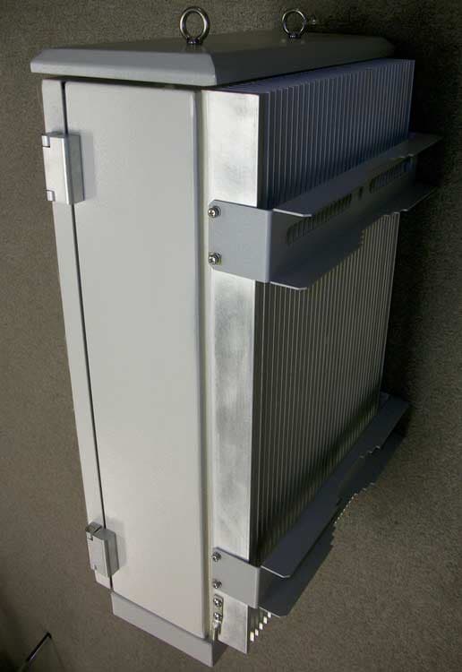
EUT: Dual Band Home Booster FCC ID: S3CDBHB-20-S8-S9 Model: DBHB-20-S8-S9 Report Number: 0048-060206-01 Advanced Compliance Laboratory, Inc. 6 Randolph Way, Hillsborough, NJ 08844, Tel: (908) 927 9288 Front View EUT: Dual Band Home Booster FCC ID: S3CDBHB-20-S8-S9 Model: DBHB-20-S8-S9 Report Number: 0048-060206-01 Advanced Compliance Laboratory, Inc. 6 Randolph Way, Hillsborough, NJ 08844, Tel: (908) 927 9288 Bottom View EUT: Dual Band Home Booster FCC ID: S3CDBHB-20-S8-S9 Model: DBHB-20-S8-S9 Report Number: 0048-060206-01 Advanced Compliance Laboratory, Inc. 6 Randolph Way, Hillsborough, NJ 08844, Tel: (908) 927 9288 AC/DC Adaptor
ID Label/Location Info
EUT: Dual Band Home Booster FCC ID: S3CDBHB-20-S8-S9 Model: DBHB-20-S8-S9 Report Number: 0048-060206-01 Advanced Compliance Laboratory, Inc. 6 Randolph Way, Hillsborough, NJ 08844, Tel: (908) 927 9288 Section 10. FCC ID Labeling FCC ID Label Location of Label on Lower Side Wall FCC LABEL FCC ID: S3CDBHB-20-S8-S9 This device complies with Part 2, 15, 90 of the FCC Rules. Operation is subject to the following two conditions: (1) this device may not cause harmful interference. and (2) this device must accept any interference received, includin g interference that may cause undesired operation.
Internal Photos
EUT: Dual Band Home Booster FCC ID: S3CDBHB-20-S8-S9 Model: DBHB-20-S8-S9 Report Number: 0048-060206-01 Advanced Compliance Laboratory, Inc. 6 Randolph Way, Hillsborough, NJ 08844, Tel: (908) 927 9288 Cover View EUT: Dual Band Home Booster FCC ID: S3CDBHB-20-S8-S9 Model: DBHB-20-S8-S9 Report Number: 0048-060206-01 Advanced Compliance Laboratory, Inc. 6 Randolph Way, Hillsborough, NJ 08844, Tel: (908) 927 9288 Open View EUT: Dual Band Home Booster FCC ID: S3CDBHB-20-S8-S9 Model: DBHB-20-S8-S9 Report Number: 0048-060206-01 Advanced Compliance Laboratory, Inc. 6 Randolph Way, Hillsborough, NJ 08844, Tel: (908) 927 9288 PCB View-top EUT: Dual Band Home Booster FCC ID: S3CDBHB-20-S8-S9 Model: DBHB-20-S8-S9 Report Number: 0048-060206-01 Advanced Compliance Laboratory, Inc. 6 Randolph Way, Hillsborough, NJ 08844, Tel: (908) 927 9288 PCB View-bottom
Parts List/Tune Up Info
SHYAM TELECOM LIMITED DUAL BAND HOME BOOSTER ( DBHB 20 ) SMR/iDEN PRODUCTION TEST PROCEDURE PART CODE: 1200 0050 004 Version. 01 Date 10 Jan. 05 Prepared By N.N Reddy Changed By: S.C.SATI Test Procedure of Dual Band Home Booster (DBHB 20) 1.0 General Description: This unit consists of down link (Forward path) and up link (Reverse path). Both links has Duplexer, LNA, Digital Attenuator, BPFs and PA with no frequency conversion UP link & DOWN link. It works at 9.0V DC. The Downlink RF received from outdoors antenna and Uplink RF is received from integrated mobile server antenna. BPFs are select band and cutoff the out band undesired frequency. The RSL is greater than –40, glow the RSL High (Red LED). When the RSL in between –60 & -40, glow the RSL Medium LED (Green) & the RSL is less than –60, glow the RSL Low LED (Yellow). D/L Align LED will blink when the system insert/release attenuation. U/L Align LED and D/L Align LED will glow when alignment was over. 2.0 Reference Documents 2.1 PTS 3.0 Test Instruments Required & Equivalent: - S.N o. TYPE MODEL / MAKE QTY. 1 Synthesized Signal Generator AGILENT/MS3633A / ANRITSU or Equivalent 02 2 Spectrum Analyzer AGILENT/MS2602A / ANRITSU or Equivalent 01 3 Regulated Power Supply (9.0V/ 2 Amps) Aplab /PULSE or DC ADOPTER 01 5 Multimeter Equivalent 01 6 Power Combiner, & 10 dB Pad 01 Each 4.0 Visual Inspection before Connecting to the supply 4.1 Check for proper mounting of the components. [Polarity of Tantalum or electrolytic cap]. Approved By Page 1 of 8 SHYAM TELECOM LIMITED DUAL BAND HOME BOOSTER ( DBHB 20 ) SMR/iDEN PRODUCTION TEST PROCEDURE PART CODE: 1200 0050 004 Version. 01 Date 10 Jan. 05 Prepared By N.N Reddy Changed By: S.C.SATI 4.2 Check for +220V AC and +9.0V DC supply short with ground. 4.3 Ensure that PCB Partition plate is in complete contact with the Heat Sink. Tighten all the screws properly. 4.4 First ensure that all the DC levels are as per PTS sheet 1 of the production test Specification. 4.5 Give 15 minute warm up time to all instruments in use. 4.6 Use DC block with Spectrum Analyzer Test Procedure 5.0 UP LINK TEST 5.1 Measure the Gate & Drain voltage of ATF 55143 as per inspection sheet in No.4 5.2 I/P & O/P voltage of ASG201 as per inspection sheet in No.5 5.3 GAIN Measurement: - Set Synthesized signal generator on desired frequency within band with RF level –60 dBm and connect it to SMA-type input connector of UP link path. Its total gain should be more than 65dB. For measuring full gain of UP link path put the jumper of 3Pin berg con. Open loop side. The total gain of this path should be around carrier as per RF tests no 7. (Refer Setup Diagram No. 01 for settings). 5.4 BANDWIDTH, FLATNESS AND REJECTION MEASUREMENT: - For this measurement network analyzer is used. The output of this path should connect to RF i/p of network analyzer and I / p of this path is connecting to RF output port of network analyzer. Then check flatness 3dB bandwidth and specified rejection. These parameters should be as per RF Test No 8. (Refer Setup Diagram No. 03 for settings). 5.5 OUTPUT POWER Measurement: - Connect SMA-type output connector to Spectrum analyzer to measure the UP link out put. The max output of this chain Approved By Page 2 of 8 SHYAM TELECOM LIMITED DUAL BAND HOME BOOSTER ( DBHB 20 ) SMR/iDEN PRODUCTION TEST PROCEDURE PART CODE: 1200 0050 004 Version. 01 Date 10 Jan. 05 Prepared By N.N Reddy Changed By: S.C.SATI is more than +10dBm as per RF test no 9. (Refer Setup Diagram No. 01 for settings). 5.6 ALC Setting: - In this unit, ALC (Automatic Level Control), controls the output power and system gain automatically. Set the POT VR201 10 dBm o/p power. And checked the dc voltage range at 3Pin berg con. Pin No. 3 increasing RF levels as per RF tests no 10. 5.7 Set Spectrum Analyzer and Signal Analyzer as: - Center Frequency: As desired Span: As per Requirement RBW / VBW / SWEEP / ATTn: AUTO 5.8 IN-BAND IMD & SPURIOUS Measurement: - For intermods measurement connect two Signal generator for two carrier output to a combiner and its output connect to Uplink input and set 7dBm level per tone by varying the RF level. Measure its intermods on same setting as per PTS RF test no 11, 12 & 13. (Refer Setup Diagram No. 02 for settings). Set start and stop frequency As per RF test no 9&10 and measure out band spurious on 100KHz RBW. 6.0 DOWN LINK TEST 6.1 Measure the Gate & Drain voltage of ATF 55143 as per inspection sheet in No.4 6.2 I/P & O/P voltage of ASG201 as per inspection sheet in No.5 6.3 GAIN Measurement: - Set Synthesized signal generator on desired frequency with RF level –60 dBm and connect it to SMA-type input connector of UP link Approved By Page 3 of 8 SHYAM TELECOM LIMITED DUAL BAND HOME BOOSTER ( DBHB 20 ) SMR/iDEN PRODUCTION TEST PROCEDURE PART CODE: 1200 0050 004 Version. 01 Date 10 Jan. 05 Prepared By N.N Reddy Changed By: S.C.SATI side. Its total gain should be more than 65dB. For measuring full gain of DOWN link path put the jumper of 3Pin berg con. Open loop side. The total gain of this path should be RF tests no 7. (Refer Setup Diagram No. 01 for settings). 6.4 BANDWIDTH, FLATNESS AND REJECTION MEASUREMENT: - For this measurement network analyzer is used. The output of this path should connect to RF i/p of network analyzer and I / p of this path is connecting to RF output port of network analyzer. Then check flatness, 3dB bandwidth and specified rejection. These parameters should be as per RF Test No 8. (Refer Setup Diagram No. 03 for settings). 6.5 OUTPUT POWER Measurement: - Connect SMA-type output connector to Spectrum analyzer to measure the Downlink out put. The max output of this chain is more than +10dBm as per RF test no 9. (Refer Setup Diagram No. 01 for settings). 6.6 Set Spectrum Analyzer and Signal Analyzer as: - 6.6.1 Center Frequency: As desired 6.6.2 Span: As per Requirement 6.6.3 RBW / VBW / SWEEP / ATT. AUTO 6.7 OUT PUT POWER SETTING: - After getting max. Gain of chain adjusts the both link O/P POWER …
Text truncated - open the document above for the full version.
Parts List/Tune Up Info
Sh y am Telecom Ltd. 4. February 2006 1 Page MATHEW As of 04/02/06BOM - with Component Location DB HB-20 800+900 Item: No.: 1200 0050 004Report ID : 50028 Qty. Description No. Level Component Location Type SNo 1200 0050 004 DB HB-20 800+900 FGD 1201 0050 004 DB HB-20 800+900 1 1 MOD 1 1204 0016 050 PCB ASSY - DB HB-20 900MHz 1 2 ASSY 2 2010 1021 303 1K,1/16W,5%,0603 25 3 CHR 3 R3,44,45,46,57,58,61,63,64,65,67,69,70,73,76,203,241,24 2,243,252,253,254,256,259,261 2010 2021 303 2K,1/16W,5%,0603 2 3 CHR 4 R72,265 2010 3321 303 3.3K,1/16W,5%,0603 1 3 CHR 5 R66 2010 3921 303 3.9K,1/16W,5%,0603 3 3 CHR 6 R5,56,205 2010 4721 303 4.7K,1/16W,5%,0603 6 3 CHR 7 R23,62,78,223,251,258 2010 5112 303 5.1E,1/16W,5%,0603 12 3 CHR 8 R10,16,27,33,36,42,210,216,227,233,236,245 2010 9121 303 9.1K, 1/16W,5%,0603 2 3 CHR 9 R6,206 2010 1001 303 10E,1/16W,±5%,0603 3 3 CHR 10 R8,68,208 2010 1031 303 10K,1/16W,5%,0603 13 3 CHR 11 R4,18,19,20,21,22,204,218,219,220,221,222,264 2010 1631 303 16K, 0603,1/16W, 5% 8 3 CHR 12 R12,29,38,48,212,229,238,247 2010 2731 303 27K,1/16W,5%,0603 2 3 CHR 13 R71,260 2010 4731 303 47K,1/16W,5%,0603 1 3 CHR 14 R77 2010 5101 303 51E,1/16W,5%,0603 24 3 CHR 15 R1,213,14,30,31,39,40,47,49,50,51,55,201,202,213,214,23 0,231,239,240,248,249,250 2010 7501 303 75E, 1/16W, 5%,0603 1 3 CHR 16 R53 2010 1011 303 100E 1/16W 5% 0603 2 3 CHR 17 R52,54 2010 2011 303 200E,1/16W,5%,0603 1 3 CHR 18 R257 2010 3011 303 300E,1/16W,5%,0603 8 3 CHR 19 R24,25,74,75,224,225,262,263 2010 4711 303 470E,1/16W,5%,0603 2 3 CHR 20 R7,207 2010 5111 303 510E,1/16W,5%,0603 1 3 CHR 21 R255 2010 9111 303 910E,1/16W,5%,0603 26 3 CHR 22 R9,11,15,17,26,28,32,34,35,37,41,43,59,60,209,211,215,2 17,226,228,232,234,235,237,244,246 2051 5011 000 VAR.RES.500E SMD 4.5xSMM(S. 2 3 VRC 23 VR1,2 2051 1021 001 1K SMD 4.5X5MM (S.T) 3 3 VRC 24 VR3,4,201 2114 1041 413 100KPF,10%,0603,16V 38 3 CHC 25 C8,9,11,12,15,21,36,41,46,54,62,64,65,66,69,74,76,77,78 ,208,209,211,212,215,221,236,244,251,259,262,263,264,265,269,271,272,273,274 2117 1021 443 1KPF 50V €10% 0603 20 3 CHC 26 C20,26,27,28,29,30,35,45,53,72,220,226,227,228,229,230, 235,243,250,257 2114 5012 843 5PF,50V,€0.25PF,0603 8 3 CHC 27 C19,34,44,52,219,234,242,249 2114 6812 343 6.8PF 50V +/-0.25%,0603 8 3 CHC 28 C18,33,43,51,218,233,241,248 2114 3012 843 3PF 50V€0.25PF,0603 2 3 CHC 29 C17,217 2114 5612 343 5.6PF,€.5PF,0603,50V 2 3 CHC 30 C5,205 Sh y am Telecom Ltd. 4. February 2006 2 Page MATHEW As of 04/02/06BOM - with Component Location DB HB-20 800+900 Item: No.: 1200 0050 004Report ID : 50028 Qty. Description No. Level Component Location Type SNo 2114 8212 343 8.2PF 50V€5% PF 0603 2 3 CHC 31 C16,216 2114 1001 343 10PF,50V,±5%,0603 2 3 CHC 32 C68,256 2115 1051 410 1MF 16V€10%,A 5 3 CTNC 33 C63,67,71,75,261 2115 1061 412 10MF, 16VÇ10%B 16 3 CTNC 34 C7,10,13,22,37,47,55,79,207,210,213,222,237,245,252,266 2114 2201 343 22PF 50V ±5%,0603 2 3 CHC 35 C81,82 2114 1011 343 100PF 50V ±5% 0603 46 3 CHC 36 C1,2,3,4,14,23,24,25,31,32,38,39,40,42,48,49,50,56,57,5 8,59,60,70,73,80,201,202,203,204,214,223,224,225,231,232,238,239,240,246,247,253,254,255,258,260,267 2114 2211 343 220PF,5%,0603,50V 1 3 CHC 37 C61 2118 1061 642 CEC - 10MFD 35V 2 3 CEC 38 C270,275 2118 1071 650 CEC - 100MFD 16V 1 3 CEC 39 C268 2295 2742 404 2.7 NH, 5% 0805 2 3 CHCL 40 L2,202 2295 1022 512 10NH,5%,1008 2 3 CHCL 41 L3,203 2295 1012 302 1UH,5%,1008 2 3 CHCL 42 L4,204 2295 5632 302 56NH, 1008 12 3 CHCL 43 L5,6,7,8,9,10,205,206,207,208,209,210 2360 0138 000 MMBT3906LT1 SOT-23 4 3 TRAN 44 Q1,3,201,203 2360 0128 000 MMBT2222A 2 3 TRAN 45 Q2,202 2302 0017 000 HSMP3890 SOT23 2 3 DIOD 46 CR1,201 2325 0003 000 HSMS 2822 SOT-23 2 3 DIOD 47 CR2,202 2309 0014 500 1N4007,SOD-123,LEAD 1 3 DIOD 48 CR203 2922 0001 000 IC - LNA ATF 55143 2 3 IC 49 U1,201 2922 0010 000 IC - Gain Block - ASG-201 8 3 IC 50 U2,4,5,6,202,204,205,206 2997 0021 000 IC-HMC273 MS10G ATT31 2 3 IC 51 U3,203 2962 0002 000 IC AD 8314 (ARM) J5A 1 3 IC 52 U7 2999 1004 000 LM 2904M SO-8 3 3 IC 53 U8,9,207 2999 1005 002 LM2941T VOLT REGULAT 1 3 IC 54 U208 2999 1004 500 LM2940 SMD IMP 5.0 V 1 3 IC 55 U209 2965 0001 000 PIC 16F876 20I/SO SMD 1 3 IC 56 U10 2685 0015 100 DUPL - DMJ 0902 KTB-25 1 3 DUPL 57 DUP1 2685 0015 000 DUPL - DMJ 0902 KTA-25 1 3 DUPL 58 DUP201 2786 0008 100 BPF - FMJ 0947 MYA-25 1 3 BPF 59 YF1 2786 0008 000 BPF - FMJ 0902 MYA-25 1 3 BPF 60 YF201 2784 1251 100 SW FLT 25.0 - 947.5/25/3.0x3.0 2 3 FILT 61 YF2,3 2784 1251 050 SW FLT 25.0 - 902.5/25/3.0x3.0 2 3 FILT 62 YF202,203 2675 3216 000 DIPLEXER DP3216 - B0918AAT 4 3 DIPL 63 DIP1,2,202,203 2676 2012 000 COUPLER - CP2012-20A0897T 3 3 COUP 64 CP1,2,201 2781 0013 105 XTAL 3.6864,30PPM(P.R) 49U 1 3 XTAL 65 XTAL1 Sh y am Telecom Ltd. 4. February 2006 3 Page MATHEW As of 04/02/06BOM - with Component Location DB HB-20 800+900 Item: No.: 1200 0050 004Report ID : 50028 Qty. Description No. Level Component Location Type SNo 2240 0120 000 SMD FERITE BEAD 120E 2 3 CFB 66 FB1,201 2809 0003 000 3PIN BERG CONN (M)ST 4 3 CONN 67 CON1,2,5,201 2809 0005 000 5 PIN BERG STICK 1 3 CONN 68 CON3 2809 0006 100 6PIN (3X2) BURG STICK 1 3 CONN 69 CON4 2809 0014 100 14PIN(7X2) BURG STICK 1 3 CONN 70 CON6 2816 0044 100 DC SOCKET 1 3 SOCK 71 SOK201 3200 0016 050 DB HB-20-900MHz 1 3 PCB 72 1224 0016 050 PCB ASSY - DB HB-20 800 MHz 1 2 ASSY 73 2010 1021 303 1K,1/16W,5%,0603 25 3 CHR 74 R3,44,45,46,57,58,61,63,64,65,67,69,70,73,76,203,241,24 2,243,252,253,254,256,259,261 2010 2021 303 2K,1/16W,5%,0603 2 3 CHR 75 R72,265 2010 3321 303 3.3K,1/16W,5%,0603 1 3 CHR 76 R66 2010 3921 303 3.9K,1/16W,5%,0603 3 3 CHR 77 R5,56,205 2010 4721 303 4.7K,1/16W,5%,0603 6 3 CHR 78 R23,62,78,223,251,258 2010 5112 303 5.1E,1/16W,5%,0603 12 3 CHR 79 R10,16,27,33,36,42,210,216,227,233,236,245 2010 9121 303 9.1K, 1/16W,5%,0603 2 3 CHR 80 R6,206 2010 1001 303 10E,1/16W,±5%,0603 3 3 CHR 81 R8,68,208 2010 1031 303 10K,1/16W,5%,0603 13 3 CHR 82 R4,18,19,20,21,22,204,218,219,220,221,222,264 2010 1631 303 16K, 0603,1/16W, 5% 8 3 CHR 83 R12,29,38,48,212,229,238,247 …
Text truncated - open the document above for the full version.
RF Exposure Info
EUT: Dual Band Home Booster FCC ID: S3CDBHB-20-S8-S9 Model: DBHB-20-S8-S9 Report Number: 0048-060206-01 Page 177 Advanced Compliance Laboratory, Inc. 6 Randolph Way, Hillsborough, NJ 08844, Tel: (908) 927 9288 Section 11. Maximum Permissible Exposure MPE estimate is given per 2.1091 of FCC Rules: Calculation Equation: S d GP 20 10 282.0 + ×= Where, P(DL)= 10dBm*, G=0 dBi (Server Antenna), P(UL)= 7dBm, G=7 dBi (Donor Antenna), and from §1.1310 Table 1 (B), S = 0.55 mW/cm 2 Plug all three items into the equation, and yields, Power Density MPE Limit (mW/ cm 2 ) Output Power (dBm) Server Antenna Gain (dBi) Donor Antenna Gain (dBi) Server MPE Distance (cm) Donor MPE Distance (cm) 0.55 10/7 0 7 1.20 1.90 *DL worst case: two DL antennas are collocated . NOTE: For mobile or fixed location transmitters, the minimum separation distance is 20 cm, even if calculations indicate that the MPE distance would be less.
Test Report
Electromagnetic Emission Compliance Test Report Equipment Under Test (EUT) Dual Band Home Booster DBHB-20-S8-S9 Applicant Shyam Telecom Inc. In Accordance With FCC Part 90, Subpart I Test by Advanced Compliance Laboratory, Inc. 6 Randolph Way Hillsborough, New Jersey 08844 Authorized by Wei Li Lab Manager Signature Date March 3, 2006 AC Lab Report Number 0048-060206-01 The test result in this report is supported and covered by the NVLAP accreditation. Lab Code:200101-0 Advanced Compliance Laboratory 6 Randolph Way Hillsborough, NJ 08844 Tel: (908) 927 9288 Fax: (908) 927 0728 EUT: Dual Band Home Booster FCC ID: S3CDBHB-20-S8-S9 Model: DBHB-20-S8-S9 Report Number: 0048-060206-01 Page 2 Advanced Compliance Laboratory, Inc. 6 Randolph Way, Hillsborough, NJ 08844, Tel: (908) 927 9288 Index Section 1. Summary of Test Results....................................................................... 3 Section 2. General Equipment Specification......................................................... 5 Section 3. RF Output Power....................................................................................... 7 Section 4. Occupied Bandwidth.............................................................................. 10 Section 5. Spurious Emissions at Antenna Terminals..................................... 60 Section 6. Field Strength of Spurious................................................................. 158 Section 7. Frequency Stability.............................................................................. 164 Section 8. Out of Band Rejec…
Text truncated - open the document above for the full version.
Contact Information
Applicant
B.A. Majmudar(Officer)
Test Firm
Advanced Compliance LaboratoryWei Li
Technical Specifications
| # | Rule Parts | Frequency Range | Power Output | Emission | Tolerance |
|---|---|---|---|---|---|
| 8 | 9 | 935 MHz - 940 MHz | 10.00 mW | F8W,F1D | Amp |
Other Applications from Shyam Telecom Inc.
S3CDB6M33SA
Jan 19, 2011DB6M Dual Band Repeater DB6M33-700UC+AWS
Equipment Class
AMP - Amplifier
S3CISR-20-1PG-MC
May 10, 2007In Door R-20 930MHz One Way Paging Repeater R-20-9
Equipment Class
TNB - Licensed Non-Broadcast Station Transmitter
S3CHB-20-S8
Dec 28, 2006Home Booster HB-20-S8
Equipment Class
TNB - Licensed Non-Broadcast Station Transmitter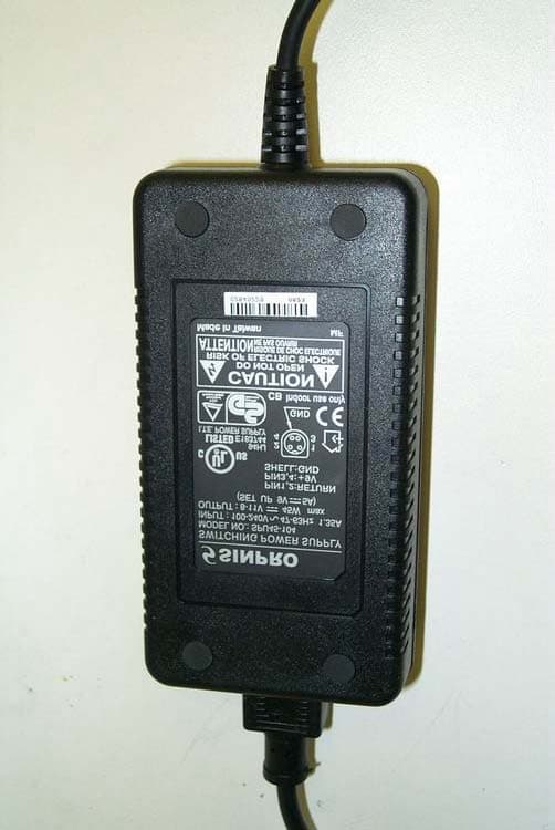
S3CDBHB-20
Aug 28, 2005Dual Band Home Booster DB-HB-20
Equipment Class
AMP - Amplifier
S3CHB-20-1900
May 31, 2005Home Booster
Equipment Class
AMP - Amplifier