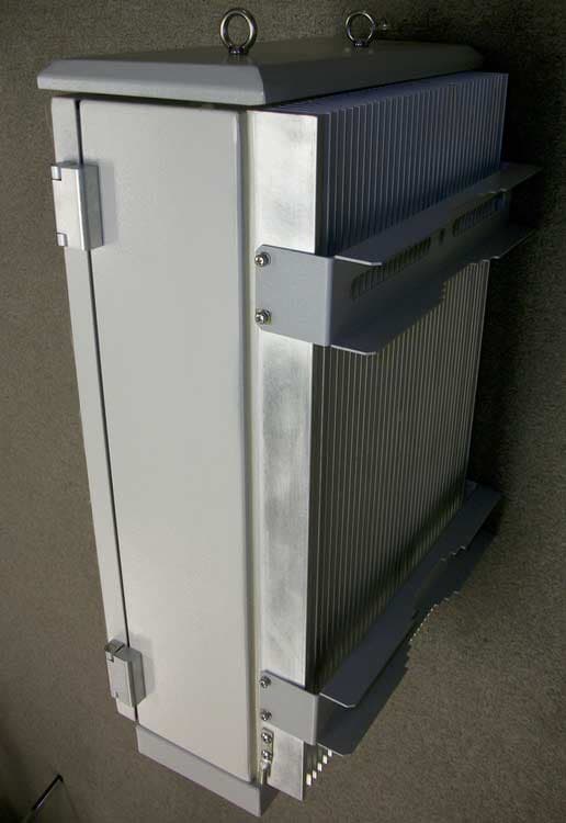
S3CHB-20-800Home Cellular Booster
Shyam Telecom Inc.
Click to zoom
Application Details
- Equipment Class
- TNB - Licensed Non-Broadcast Station Transmitter
- Date of Grant
- Mar 20, 2005
- Application Purpose
- Original Equipment
- Date of Application
- Mar 20, 2005
- Equipment Note
- Home Cellular Booster
- Frequency Range
- 869.00000000 - 894.00000000
- Company
- Shyam Telecom Inc.
- Country
- United States
Documents & Files
Document Text
Text extracted from the exhibit documents filed with the FCC. Open a document above to read the original.
Users Manual
File Doc. No. Date Version Page HB-20 5700 9004 050 Feb 05 1.0 1/12 Antenna – Electronic Communication Systems Home Booster I I N N S S T T A A L L L L A A T T I I O O N N A A N N D D O O P P E E R R A A T T I I O O N N M M A A N N U U A A L L H H B B - - 2 2 0 0 Home Booster 800 MHz Proprietary Information The information contained herein is proprietary to Shyam Telecom Limited. Use or disclosure of this document or the information contained herein, for any purpose other than that for which it was furnished is not permitted or it shall not be disclosed or divulged to any third Party without the prior written consent of Shyam Telecom Limited. 5700 9004 050 REV. 1.0 Feb, 2005 SHYAM Telecom Ltd. A-60, Naraina Industrial Area, Phase-I, New Delhi-110028 (INDIA) Tel: +91-11-51411076 Fax: +91-11-51411078 Email: [email protected] File Doc. No. Date Version Page HB-20 5700 9004 050 Feb 05 1.0 2/12 Antenna – Electronic Communication Systems Contents PREAMBLE ..................................................................................................3 About the manual .......................................................................................3 1.0 About the manual ................................................................................4 2.0 Important Safety Information ............................................................4 3.0 Introduction: Booster Theory / Background ..................................5 4.0 Description of HB-20 Booster installation Kit ...............................6 5.0 System Design and Setup .................................................................7 6.0 Installing the HB-20 .............................................................................7 6.1 Pre-installation considerations .................................................................7 6.2 Installation Tools ......................................................................................7 6.3 Installation Procedure: Do It Yourself .....................................................8 6.4 Power Startup / Alarm Checks / Coverage Testing .................................8 6.5 Display Details of HB-20 ..........................................................................9 Technical Specification: Boosters HB-20 ...............................................10 Trouble shooting procedure HB-20 ........................................................11 File Doc. No. Date Version Page HB-20 5700 9004 050 Feb 05 1.0 3/12 Antenna – Electronic Communication Systems PREAMBLE In cellular systems boosters / repeaters are used, to enhance the coverage of a Base station in a region where, due to topological conditions, poor field strengths disable communication. SHYAM is a leading manufacturer of boosters / repeaters. These boosters / repeaters provide excellent electrical characteristics, are lightweight and easy to install. Any intervention has to be performed by authorized persons only. If you need technical assistance, please contact at the following address: SHYAM Telecom Ltd. A-60, Naraina Industrial Area, Phase-I, New Delhi-110028 (INDIA) Tel: +91-11-51411076 Fax: +91-11-51411078 Email: [email protected] Under consideration of all references given in this manual, the repeater should be taken into service without any complications and should operate trouble free for a long time. However we have country wide after sales support network to assist you if required. Please visit to our web site www.shyamtelecom.com for our country wide after sales support offices. About the manual The “ Installation and Operation manual ” is intended to be used for SHYAM HB-20 Booster installation. It contains the general guidelines for the field engineers /technicians. Read carefully before starting the installation. File Doc. No. Date Version Page HB-20 5700 9004 050 Feb 05 1.0 4/12 Antenna – Electronic Communication Systems 1.0 About the manual The “Installation and Operation manual” is intended to be used for SHYAM HB-20 booster installation. It contains the general guidelines for the person installing the HB-20 booster. Read carefully before starting the HB-20 booster installation. 2.0 Important Safety Information The HB-20 booster has been designed for maximum safety when installed and operated according to the instructions in this manual. Refer to all safety instructions as per the antenna installation instruction sheets. Do not bypass any of the safety features with the equipment provided, nor operate the system in an inappropriate environment. WARNING! Installation of antennas near power lines is dangerous. For your safety, follow all installation directions and keep safe distance from any high voltage power lines that could result in shock or loss of life. WARNING! This equipment complies with FCC & IC radiation exposure limits set forth for an uncontrolled environment. This transmitter must not be co-located or operating in conjunction with any other antenna or transmitter. The signal booster with server antenna must be installed to provide minimum 20 cm separation distance between the server antenna to the body of user or near by person. The donor antenna used for this transmitter must be fixed-mounted on outdoor permanent structures with a separation distance of at least 1.5 meters from all persons during normal operation. Additional wiring required to install the HB-20 system should comply with national or local governing Electrical Codes. Indoor RF coaxial cable installations should comply with local Electrical Code requirements. The HB-20 booster is designed for indoor application. The housing is not waterproof, so please keep it away from water, rain and any chemical liquid. Do discharge the static before you touch the connectors of the booster. Do not open the module inside the booster unless you are authorized. The power supply unit in the HB-20 booster is supplied from the mains (primary AC power) that contains dangerous voltage level which will cause el…
Text truncated - open the document above for the full version.
Cover Letter(s)
Mike Kuo From: [email protected] Sent: Thursday, March 17, 2005 7:55 PM To: Mike Kuo Cc: [email protected] Subject: Re: FW: Shyam Telecom Inc., FCC ID: S3CHB-20-800, Assessment NO.: AN05T4634,... 3/18/2005 HI, Mike. Finally, we got most of answers for your questions. Revised report is also attached. Q#2, 9 11 will be provided tomorrow. In a message dated 2005-3-17 14:12:44 Eastern Standard Time, [email protected] writes: Subject: Shyam Telecom Inc., FCC ID: S3CHB-20-800, Assessment NO.: AN05T4634, Notice#1 Question #1: Please provide technical information to address the following required information as listed in the section 2.1033 (c)(8) and (9). Please see report pg. 5. Question #2: The information included in the theory of operation are copied from user manual. Please provide revised theory of operation to address the following requirement: a description of all circuitry and devices provided for determining and stabilizing frequency, for suppression of spurious radiation , for limiting modulation, and for limiting power. Next email. Question #3: This booster comes with two antenna connectors. One is connected to Server indoor antenna and the other one is connected to donor outdoor antenna. Please explain which antenna connector was connected during the output power measurement. See report page 9-20 test configuration: Siganl generator was connected to Server antenna connector for UL test and to Donor antenna connector. Question #4: Please submit all output power spectrum plots for uplink and downlink. Please see report page 9-20. Question #5: What is the input power level used during output power measurement. -50dBm. See report page 8-20. Question #6: Based upon the technical specification in the user manual, this booster has automatic power level control for not to exceed 10dBm. However, the measured output power is above this level, please explain. The output of Cellular booster is +16 dbm. The power auto control is the output power adjustment range which can be adjusted manually. Question #7 : On the TCB application form, the output power listed for uplink and downlink is 400mW, please provide information to justify this value. Typo. Should be 0.04W=40mW from max. output power 16dBm. Question #8: Is this booster capable of channel translation ? No. Question #9:Please submit a cover to acknowledge the booster / repeater must meet all criteria stated in Sections 90.219 and 22.383 for related booster/in building operations. Next email. Question #10: Device operates in part 22H of FCC rules is subject to routine RF evaluation per section 2.1091 of FCC rules. Please provide MPE estimate based upon the output power measured Vs the max. antenna gain allowed. The MPE estimate must be within 20 cm . See report page 80. Question #11: User manual does not include RF exposure information to the end user, please include such warning statement based upon the MPE estimate. Next email. Question #12: If internal photos is requested as confidential document, please provide strong justification why the internal photos is confidential. No request. Best regards, Wei 3/18/2005
Cover Letter(s)
1 Mike Kuo From: Mike Kuo Sent: Monday, March 21, 2005 10:09 AM To: '[email protected]' Subject: FW: Shyam Telecom Inc., FCC ID: S3CHB-20-800, Assessment NO.: AN05T4634,, Notice# 2 Attachments: 90.219 and 22.383 statement.doc 90.219 and 22.383 statement.do... -----Original Message----- From: [email protected] [mailto:[email protected]] Sent: Monday, March 21, 2005 3:20 PM To: Mike Kuo Subject: Re: FW: Shyam Telecom Inc., FCC ID: S3CHB-20-800, Assessment NO.: AN05T4634,... Hi, Mike. Here is the answer for those questions: 1. Report is revised for output power plots. 2. The letter for 90.219, 22.383 is done and will be sent to you today. 3. Revised manual is here. 4. Revised MPE page is in the new report. 5. Output power limitation is 16dBm. The 10dB auto level control range is manually set to adjust the power output from 6dBm to 16dBm. Hopely, this is all:-)))((( Regards, Wei -----Original Message----- From: Mike Kuo Sent: Monday, March 21, 2005 9:57 AM To: '[email protected]' Subject: FW: Shyam Telecom Inc., FCC ID: S3CHB-20-800, Assessment NO.: AN05T4634,, Notice# 2 -----Original Message----- From: Mike Kuo Sent: Friday, March 18, 2005 3:03 PM To: '[email protected]' Subject: Shyam Telecom Inc., FCC ID: S3CHB-20-800, Assessment NO.: AN05T4634,, Notice#2 -----Original Message----- From: Compliance Certification Services [mailto:[email protected]] Sent: Friday, March 18, 2005 2:32 PM To: Mike Kuo Subject: Shyam Telecom Inc., FCC ID: S3CHB-20-800, Assessment NO.: AN05T4634,, Notice#2 Second notice based upon the replies to the first notice Question #1: Based upon the spectrum plots submitted for output power measurement, the RBW 2 used is less than 20dB bandwidth which will resulting under estimated of output power. Please redo the output power measurement with RBW greater than 20dB BW. Question #2: Please submit a manufacturer statement to address section 90.219, 22.383 requirements. Attached please find the letter format. Question #3 : Please revised the RF exposure warning statement with the following statement: WARNING! This equipment complies with FCC & IC radiation exposure limits set forth for an uncontrolled environment. This transmitter must not be co-located or operating in conjunction with any other antenna or transmitter. The signal booster with server antenna must be installed to provide minimum 20 cm separation distance between the server antenna to the body of user or near by person. The donor antenna used for this transmitter must be fixed-mounted on outdoor permanent structures with a separation distance of at least 1.5 meters from all persons during normal operation. Question #3: Based upon MPE estimate, the antenna gain for server antenna is 0 dBi. However, there is no MPE estimate for the donor antenna. Please revise MPE estimate by including the max. donor antenna gain will be used. MPE estimate with donor antenna will be used to determine the separation distance as suggested in question 2. Question #4: Your reply to question #6 is not clear. What is output power limitation for this booster ? Best Regards Mike Kuo The items indicated above must be submitted before processing can continue on the above referenced application. Failure to provide the requested information within 30 days of the original e-mail date may result in application dismissal and forfeiture of the filing fee. Also, please note that partial responses increase processing time and should not be submitted. Any questions about the content of this correspondence should be directed to the e-mail address listed below the name of the sender.
External Photos
EUT: Home Cellular Booster Model: HB-20-800 Report Number: 0048-050221-01-800 Page 74 of 79 Advanced Compliance Laboratory, Inc. 6 Randolph Way, Hillsborough, NJ 08844, Tel: (908) 927 9288 Section 11. EUT Photos EUT: Home Cellular Booster Model: HB-20-800 Report Number: 0048-050221-01-800 Page 75 of 79 Advanced Compliance Laboratory, Inc. 6 Randolph Way, Hillsborough, NJ 08844, Tel: (908) 927 9288
ID Label/Location Info
EUT: Home Cellular Booster Model: HB-20-800 Report Number: 0048-050221-01-800 Page 73 of 79 Advanced Compliance Laboratory, Inc. 6 Randolph Way, Hillsborough, NJ 08844, Tel: (908) 927 9288 Section 10. FCC ID Labeling FCC ID Label Location of Label on Lower Side Wall FCC LABEL FCC ID: S3CHB-20-800 This device complies with Part 2, 15 & 22 of the FCC Rules. Operation is subject to the following two conditions: (1) this device may not cause harmful interference. an d (2) this device must accept any interference received, including interference that may cause undesired
Internal Photos
EUT: Home Cellular Booster Model: HB-20-800 Report Number: 0048-050221-01-800 Page 76 of 79 Advanced Compliance Laboratory, Inc. 6 Randolph Way, Hillsborough, NJ 08844, Tel: (908) 927 9288 EUT: Home Cellular Booster Model: HB-20-800 Report Number: 0048-050221-01-800 Page 77 of 79 Advanced Compliance Laboratory, Inc. 6 Randolph Way, Hillsborough, NJ 08844, Tel: (908) 927 9288 EUT: Home Cellular Booster Model: HB-20-800 Report Number: 0048-050221-01-800 Page 78 of 79 Advanced Compliance Laboratory, Inc. 6 Randolph Way, Hillsborough, NJ 08844, Tel: (908) 927 9288
Operational Description
File Doc. No. Date Version Page HB-20 March18th 2005 1.0 1/5 Antenna – Electronic Communication Systems Home Booster C C i i r r c c u u i i t t D D e e s s c c r r i i p p t t i i o o n n H H B B - - 2 2 0 0 Home Booster 800 MHz Proprietary Information The information contained herein is proprietary to Shyam Telecom Limited. Use or disclosure of this document or the information contained herein, for any purpose other than that for which it was furnished is not permitted or it shall not be disclosed or divulged to any third Party without the prior written consent of Shyam Telecom Limited. SHYAM Telecom Ltd. A-60, Naraina Industrial Area, Phase-I, New Delhi-110028 (INDIA) Tel: +91-11-51411076 Fax: +91-11-51411078 Email: [email protected] File Doc. No. Date Version Page HB-20 March18th 2005 1.0 2/5 Antenna – Electronic Communication Systems Detailed Circuit Description Down-Link Path Duplexer (Down-Link) The main function of duplexer is to isolate the uplink frequency from the downlink frequency, i.e. isolate transmit path from receive path. The bandwidth of the duplexer filter depends upon the frequency band. The duplexer used in the HB- 1isolate the uplink frequency from 824 Mhz to 849 Mhz and passes the Down link frequency 869 to 894 Mhz. 1 st Stage Band Pass Filter (Down-Link) The band pass filter (YF1) used in HB-1 is of high selectivity it provides the high rejection to out of band signals and passes the desired band of 869 to 894 Mhz. Low Noise Amplifier : LNA LNA receives the low signal from donor antenna and amplifies it .The main function of LNA is to amplify the low signal without adding noise. The LNA used in the HB-1 is U1.The gain of the amplifier is 30db with low noise figure of 2db. 2 nd stage amplifier:- The second stage amplifier is U2 it is also a high gain and low noise figure device. The main function of the device is to amplify the down link signal. 2 nd Stage Band Pass Filter (Down-Link) The band pass filter (YF2) used in HB-1 is of high selectivity it provides the high rejection to out off band signals and passes the desired band of 869 to 894 Mhz. 1 st Attenuator:- The digital attenuator used in HB-1 (U3) is for attenuating the highly signal. The attenuator used in HB-1 is of 31 db . The attenuation is controlled by the controller automatically the controller can increase or decrease the attenuation in the step of one db. 2nd Attenuator:- File Doc. No. Date Version Page HB-20 March18th 2005 1.0 3/5 Antenna – Electronic Communication Systems The second attenuator (CR1) is analog attenuator and controlled by the output DC voltage of the final stage power amplifier. It also provides the automatic level control apart from the digital attenuator. 3rd Stage amplifier:- The 3rd stage amplifier (U4) is also a high gain and low noise figure device. The main function of the device is to amplify the down link signal. 3 rd Stage Band Pass Filter (Down-Link) The 3rd band pass filter (YF3) used in HB-1 is of high selectivity it provides the high rejection to out off band signals and passes the desired band of 869 to 894 Mhz. The 2nd band pass filter used for high rejection and to provide high selectivity to the desired band. Pre Amplifier Stage:- The filtered signal is feed to the preamplifier stage (U5). The amplifier amplify the signal to the sufficient level so that it can be feed to the input of the power amplifier. Power Amplifier Stage:- The final stage of the HB-1 is the power amplifier (U6). The amplifier is an liner amplifier. Due to high linearity the intermodulation products are very low. File Doc. No. Date Version Page HB-20 March18th 2005 1.0 4/5 Antenna – Electronic Communication Systems UP - Link Path Duplexer (Up-Link) The main function of duplexer is to isolate the uplink frequency from the downlink frequency, i.e. isolate transmit path from receive path. The bandwidth of the duplexer filter depends upon the frequency band. The duplexer used in the HB-1 passes the uplink frequency from 824 Mhz to 849 Mhz and isolate the Down link frequency 869 to 894 Mhz. 1 st Stage Band Pass Filter (Up-Link) The band pass filter (YF201) used in HB-1 is of high selectivity it provides the high rejection to out of band signals and passes the desired band of 824 to 849 Mhz. Low Noise Amplifier : LNA LNA receives the low signal from server antenna and amplifies it .The main function of LNA is to amplify the low signal without adding noise. The LNA used in the HB-1 is U201.The gain of the amplifier is 30db low noise figure of 2db. 2 nd stage amplifier:- The second stage amplifier is U202 it is also a high gain and low noise figure device. The main function of the device is to amplify the up link signal. 2 nd Stage Band Pass Filter (Down-Link) The band pass filter (YF202) used in HB-1 is of high selectivity it provides the high rejection to out off band signals and passes the desired band of 824 to 849 Mhz. 1 st Attenuator:- The digital attenuator used in HB-1 (U203) is for attenuating the highly signal. The attenuator used in HB-1 is of 31 db . The attenuator is controlled by the controller automatically the controller can increase or decrease the attenuation in the step of one db. 2nd Attenuator:- File Doc. No. Date Version Page HB-20 March18th 2005 1.0 5/5 Antenna – Electronic Communication Systems The second attenuator (CR1) is analog attenuator and controlled by the output DC voltage of the final stage power amplifier. It also provides the automatic level control apart from the digital attenuator. 3rd Stage amplifier:- The 3rd stage amplifier (U4) is also a high gain and low noise figure device. The main function of the device is to amplify the down link signal. 3 rd Stage Band Pass Filter (Down-Link) The 3rd band pass filter (YF3) used in HB-1 is of high selectivity it provides the high rejection to out off band signals and passes the desired band of 869 to 894 Mhz. The 3rd band pass filter used for high rejection and to provide high selectivity to the desired band. Pre…
Text truncated - open the document above for the full version.
Test Report
Electromagnetic Emission Compliance Test Report Equipment Under Test (EUT) Home Cellular Booster HB-20-800 Applicant Shyam Telecom Inc. In Accordance With FCC Part 22, Subpart H Test by Advanced Compliance Laboratory, Inc. 6 Randolph Way Hillsborough, New Jersey 08844 Authorized by Wei Li Lab Manager Signature Date March 1, 2005 AC Lab Report Number 0048-050221-01-800 The test result in this report is supported and covered by the NVLAP accreditation. Lab Code:200101-0 Advanced Compliance Laboratory 6 Randolph Way Hillsborough, NJ 08844 Tel: (908) 927 9288 Fax: (908) 927 0728 EUT: Home Cellular Booster Model: HB-20-800 Report Number: 0048-050221-01-800 Page 2 of 93 Advanced Compliance Laboratory, Inc. 6 Randolph Way, Hillsborough, NJ 08844, Tel: (908) 927 9288 Index Section 1. Summary of Test Results........................................................................3 Section 2. General Equipment Specification..........................................................5 Section 3. RF Output Power........................................................................................7 Section 4. Occupied Bandwidth..............................................................................21 Section 5. Spurious Emissions at Antenna Terminals......................................35 Section 6. Field Strength of Spurious....................................................................71 Section 7. Frequency Stability.................................................................................78 Section 8. Test Equipment List................................................................................79 Section 9. FCC ID Labeling.......................................................................................80 Section 10. Maximum Permissible Exposure.......................................................81 Section 11. Setup Photos..........................................................................................82 Section 12. EUT Photos.............................................................................................87 EUT: Home Cellular Booster Model: HB-20-800 Report Number: 0048-050221-01-800 Page 3 of 93 Advanced Compliance Laboratory, Inc. 6 Randolph Way, Hillsborough, NJ 08844, Tel: (908) 927 9288 Section 1. Summary of Test Results Manufacturer: Shyam Telecom Inc. Model No.: Home Cellular Booster HB-20-800 Sample No.: HDCE-020002 General: All measurements are traceable to national standards These tests were conducted on a sample of the equipment for the purpose of demonstrating compliance with FCC Part 22, Subpart H. New Submission Production Unit Class II Permissive Change Pre-Production Unit THIS TEST REPORT RELATES ONLY TO THE ITEM(S) TESTED. THE FOLLOWING DEVIATIONS FROM, ADDITIONS TO, OR EXCLUSIONS FROM THE TEST SPECIFICATIONS HAVE BEEN MADE. “See Summary of Test Data” NVLAP LAB CODE: 200101-0 Advance Compliance Laboratory, Inc. authorizes the above named company to reproduce this report provided it is reproduced in its entirety and for use by the company’s employees only. Any use which a third party makes of this report, or any reliance on or decisions to be made based on it, are the responsibility of such third parties. Advance Compliance Laboratory, Inc. accepts no responsibility for damages, if any, suffered by any third party as a result of decisions made or actions based on this report. This report applies only to the items tested. EUT: Home Cellular Booster Model: HB-20-800 Report Number: 0048-050221-01-800 Page 4 of 93 Advanced Compliance Laboratory, Inc. 6 Randolph Way, Hillsborough, NJ 08844, Tel: (908) 927 9288 Summary of Test Data RF Power Output 22.913(a) 500W ERP Complies Occupied Bandwidth (Voice & SAT) 22.917(c) Mask N/A* Occupies Bandwidth (Wideband Data) 22.917(d) Mask N/A* Occupied Bandwidth (Digital) 22.917(d) Mask Complies Spurious Emissions at Antenna Terminals 22.917 -13 dBm Complies Field Strength of Spurious Emissions 22.917 -13 dBm E.I.R.P. Complies Frequency Stability 22.355 1.5 ppm N/A* * These items are NOT applied to the EUT. The estimated uncertainty of the test result is given as following. The method of uncertainty calculation is provided in Advanced Compliance Lab. Doc. No. 0048-01-01. Prob. Dist. Uncertainty(dB) Uncertainty(dB) Uncertainty(dB) 30-1000MHz 1-6.5GHz Conducted Combined Std. Uncertainty u c norm. ±2.36 ±2.99 ±1.83 Wei Li Date: March 1, 2005 Lab Manager Advanced Compliance Lab EUT: Home Cellular Booster Model: HB-20-800 Report Number: 0048-050221-01-800 Page 5 of 93 Advanced Compliance Laboratory, Inc. 6 Randolph Way, Hillsborough, NJ 08844, Tel: (908) 927 9288 Section 2. General Equipment Specification Supply Voltage 9V DC Downlink: 869-894MHz Uplink: 824-849MHz Frequency Range Modulation CDMA (F9W) GSM (GXW) NADC (DXW) CDPD (F9W) AMPS (F8W, F1D) Output Impedance 50ohm F1-F1 F1-F2 N/A Frequency Translation Software Duplexer Change Full Band Coverage DC voltages and DC currents per 2.1033(c)(8) The input supply to the transmitter was set at 9 Volts DC. The RF power output was measured with the indicated voltage and current applied into the final RF amplifying device(s). 800 MHz Digital CDMA RF Output, DC Current and RF Input Power are all average values. Measured Maximum RF output: 14.7dBm (0.03W) Measured DC voltage: 9.1V Measured DC current: 672mA. Measured Minimum RF output: -55.2dBm Measured DC voltage: 9.1V Measured DC current: 660mA Tune-up procedure per 2.1033(c) (9) There are no user accessible adjustments or tuning in this portable cellular transceiver. All necessary adjustments and tuning are performed during manufacture of the product. Any adjustments or tuning after service or repair are done as part of that process as special equipment is required to perform such adjustments. EUT: Home Cellular Booster Model: HB-20-800 Report Number: 0048-050221-01-800 Page 6 of 93 Advanced Compliance Laboratory, Inc. 6 Randolph Way, Hillsborough, NJ 08844, Tel: (908) 927 9288 Description of Operation Th…
Text truncated - open the document above for the full version.
Test Setup Photos
EUT: Home Cellular Booster Model: HB-20-800 Report Number: 0048-050221-01-800 Page 68 of 79 Advanced Compliance Laboratory, Inc. 6 Randolph Way, Hillsborough, NJ 08844, Tel: (908) 927 9288 Section 9. Setup Photos RF Output Power EUT: Home Cellular Booster Model: HB-20-800 Report Number: 0048-050221-01-800 Page 69 of 79 Advanced Compliance Laboratory, Inc. 6 Randolph Way, Hillsborough, NJ 08844, Tel: (908) 927 9288 Spurious Emissions at Antenna Terminal EUT: Home Cellular Booster Model: HB-20-800 Report Number: 0048-050221-01-800 Page 70 of 79 Advanced Compliance Laboratory, Inc. 6 Randolph Way, Hillsborough, NJ 08844, Tel: (908) 927 9288 Occupied Bandwidth EUT: Home Cellular Booster Model: HB-20-800 Report Number: 0048-050221-01-800 Page 71 of 79 Advanced Compliance Laboratory, Inc. 6 Randolph Way, Hillsborough, NJ 08844, Tel: (908) 927 9288 Field Strength of Spurious Configuration I: Downlink with Server Antenna Configuration II: Downlink with Mobile Port Terminated EUT: Home Cellular Booster Model: HB-20-800 Report Number: 0048-050221-01-800 Page 72 of 79 Advanced Compliance Laboratory, Inc. 6 Randolph Way, Hillsborough, NJ 08844, Tel: (908) 927 9288 Configuration III: Uplink with BTS Port Terminated
Contact Information
Applicant
B.A. Majmudar(Officer)
Test Firm
Advanced Compliance LaboratoryWei Li
Technical Specifications
| # | Rule Parts | Frequency Range | Power Output | Emission | Tolerance |
|---|---|---|---|---|---|
| 2 | 22H | 869 MHz - 894 MHz | 35.00 mW | F9W | Amp |
Other Applications from Shyam Telecom Inc.
S3CDB6M33SA
Jan 19, 2011DB6M Dual Band Repeater DB6M33-700UC+AWS
Equipment Class
AMP - Amplifier
S3CISR-20-1PG-MC
May 10, 2007In Door R-20 930MHz One Way Paging Repeater R-20-9
Equipment Class
TNB - Licensed Non-Broadcast Station Transmitter
S3CHB-20-S8
Dec 28, 2006Home Booster HB-20-S8
Equipment Class
TNB - Licensed Non-Broadcast Station Transmitter
S3CDBHB-20-S8-S9
Mar 21, 2006Dual Band Home Repeater DBHB-20-S8-S9
Equipment Class
AMP - Amplifier
S3CDBHB-20
Aug 28, 2005Dual Band Home Booster DB-HB-20
Equipment Class
AMP - Amplifier