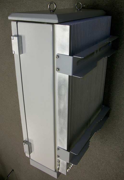
S3CIRD55FB-30-70Dual Band Repeater
Shyam Telecom Inc.
Click to zoom
Application Details
- Equipment Class
- AMP - Amplifier
- Date of Grant
- May 11, 2005
- Application Purpose
- Original Equipment
- Date of Application
- May 11, 2005
- Equipment Note
- Dual Band Repeater
- Frequency Range
- 1930.00000000 - 1990.00000000
- Company
- Shyam Telecom Inc.
- Country
- United States
Documents & Files
Document Text
Text extracted from the exhibit documents filed with the FCC. Open a document above to read the original.
Users Manual
Antenna – Electronic Communication Systems R-30 Series Repeater Model No. IRD55FB-30-70 O O P P E E R R A A T T I I O O N N M M A A N N U U A A L L D D B B - - 5 5 R R - - 3 3 0 0 Dual Band Repeater Two Sub-bands in Cellular (A” A+A’ or B+B’) Up To Three Sub-Bands in PCS-1900 Doc No 5700 9006 530 VERSION 1.1 04 Mar, 2005 Proprietary Information The information contained herein is proprietary to Shyam Telecom Limited. Use or disclosure of this document or the information contained herein, for any purpose other than that for which it was furnished is not permitted or it shall not be disclosed or divulged to any third Party without the prior written consent of Shyam Telecom Limited. Mktg. Office: SHYAM Telecom Ltd. C-138, Naraina Industrial Area, Phase-I, New Delhi-110028 (INDIA) Tel: 91 11 2579 8544 Fax: 91 11 2579 0726 Email: [email protected] 1 Antenna – Electronic Communication Systems Contents PREAMBLE.......................................................................................3 1.0 About the manual........................................................................3 2.0 Important Safety Information.......................................................3 3.0 Introduction: Repeater Theory / Background..............................4 4.0 Description of DB-5R-30 Repeater Kit......................................5 4.1 System Block Diagram...................................................................6 4.2 Contents of delivery:...................................................................7 4.2.1 DONOR ANTENNA..................................................................7 Figure 4.2.1 : Donor Antenna..............................................................7 4.2.2 CONVERTER MODULE..........................................................7 Figure 4.2.2 : Converter Module........................................................7 4.2.3 Controller module (Supervisory)..............................................8 Figure 4.2.3 : Monitoring and controller module.................................8 5.0 Typical In-Building Coverage......................................................9 6.0 Installing the DB-5R-30...............................................................9 6.1 Pre-installation Considerations...................................................9 6.2 Installation Tools.......................................................................10 6.4 Display Details of DB-5R-30.....................................................12 6.5 In-Building Coverage Problems................................................13 6.6 Antenna Isolation......................................................................14 6.7 Additional Parts you will need (Optional)....................................15 Coaxial Cable Recommendations..............................................15 Trouble shooting procedure...............................................................16 Technical Specification: Repeaters DB-5R-30...................................17 2 Antenna – Electronic Communication Systems PREAMBLE In cellular systems repeaters are used, to enhance the coverage of a base station in a region where, due to topological conditions, poor field strengths disable communication. SHYAM is a leading manufacturer of repeaters. These repeaters provide excellent electrical characteristics, are lightweight and easy to install. Any intervention has to be performed by authorized persons only. If you need technical assistance, please contact at the following address: SHYAM Telecom Ltd. C-138, Naraina Industrial Area, Phase-I, New Delhi-110028 (INDIA) Tel: 91 11 2579 8544 Fax: 91 11 2579 0726 Email: [email protected] Under consideration of all references given in this manual, the repeater should be taken into service without any complications and should operate trouble free for a long time. However we have country wide after sales support network to assist you if required. Please visit to our web site www.shyamtelecom.com for our country wide after sales support offices. 1.0 About the manual The “Operation manual” is intended to be used for SHYAM DB-5R-30 repeater installation. It contains the general guidelines for the field engineers /technicians. Read carefully before starting the DB-5R-30 repeater installation. 2.0 Important Safety Information The DB-5R-30 repeater has been designed for maximum safety when installed and operated according to the instructions in this manual. Refer to all safety instructions as per the antenna installation instruction sheets. Do not bypass any of the safety features with the equipment provided, nor operate the system in an inappropriate environment. 3 WARNING! Installation of antennas near power lines is dangerous. For your safety, follow all installation directions and keep safe distance from any high voltage power lines that could result in shock or loss of life. 4 Antenna – Electronic Communication Systems WARNING! This equipment complies with FCC & IC radiation exposure limits set forth for an uncontrolled environment. This transmitter must not be co- located or operating in conjunction with any other antenna or transmitter. For mobile or fixed location transmitters, the minimum separation distance is greater than 40 cm, even if calculations indicate that the MPE distance would be less. Additional wiring required to install the DB-5R-30 system should comply with national or local governing Electrical Codes. Indoor RF coaxial cable installations should comply with local Electrical Code requirements. The DB-5R-30 repeater should only be installed in restricted access areas such as dedicated equipment rooms or closets. The DB-5R-30 repeater is designed for indoor application; the housing is not waterproof. So please keep it away from water, rain and any chemical liquid. Do discharge the static before you touch the connectors of the repeater. Do not open the module inside the repeater unless you are authorized. The power supply unit in the…
Text truncated - open the document above for the full version.
Cover Letter(s)
From: Michael Heckrotte Sent: Monday, April 18, 2005 2:21 PM To: '[email protected]' Subject: FW: Shyam Telecom Inc., FCC ID: S3CIRD55FB-30-70, Assessment NO.: AN05T4695, Notice#1 -----Original Message----- From: Compliance Certification Services [mailto:[email protected]] Sent: Monday, April 18, 2005 12:36 PM To: Michael Heckrotte Subject: Shyam Telecom Inc., FCC ID: S3CIRD55FB-30-70, Assessment NO.: AN05T4695, Notice#1 1. Request for confidentiality listed block diagram but block diagram is embedded in the user manual. User manual is not listed as confidential document. Please remove block diagram from user manual or update the request for confidentiality. 2. Description of circuitry contains theory of operation information but it is not considered as confidential document. Please confirm that this is not a confidential document or update the request for confidentiality. 3. Applicant is hereby notified that FCC Rules Part 22.383 states that Licensees may install and operate in-building radiation systems without applying for authorization or notifying the FCC, provided that the locations of the in- building radiation systems are within the protected service area of the licensee's authorized transmitter(s) on the same channel or channel block. 4. Please provide internal photographs of all subassemblies, including the front and back of each PC Board. 5. The schematic only shows the 800 MHz Downlink. Please provide schematics for the entire unit. 6. The schematic shows capacity for 4 sub bands, however the block diagram shows capacity for 3 sub bands in one service (PCS, according to the user manual) and 2 sub bands in the other service (Cellular, according to the user manual). Please explain. 7. The stages described in the theory of operation do not match the stages shown in the block diagram. Please update documentation to make these consistent. 8. Please provide the factory tune up procedure. 9. The output power in the test report is the power per carrier however the user manual specifies the power as composite. Additionally the rated composite power is less than the measured power per carrier. Please explain. 10. Please update the user manual to include specifications regarding the maximum input drive rating. 11. Please provide plots showing the input signals for occupied bandwidth measurements, for each modulation type. 12. Please provide test data showing the occupied bandwidth in the PCS bands. 13. Please provide test data and/or describe the means to control maximum power and assure linear operation. 14. Please provide conducted spurious plots from 30 MHz to 5.8 GHz for the following: PCS Band, Uplink, GSM High channel PCS Band, Uplink, GSM Mid channel PCS Band, Downlink, CDMA High channel PCS Band, Downlink, CDMA Mid channel PCS Band, Downlink, GSM High channel PCS Band, Downlink, GSM Mid channel 15. Please describe the number of input signals, including the frequency and drive level for each input signal, that were used for intermodulation tests. 16. The radiated spurious data shows substitution measurements to 19.898 GHz, however the equipment list only shows equipment with a maximum frequency of 3 GHz for signal generators and 18 GHz for antennas. Please explain. 17. The frequency stability table on page 167 indicates a signal in the range of 1.9 MHz, however the band under test is in the range of 1.9 GHz. Please explain. 18. Please provide test data to show the out of band rejection, or submit frequency response plots for each filter that provides out of band rejection. 19. RF Exposure: The calculated MPE distance is more than 20 cm but in the user manual, only 20 cm separation distance is required. Please make the necessary changes to the user manual. The items indicated above must be submitted before processing can continue on the above referenced application. Failure to provide the requested information within 30 days of the original e-mail date may result in application dismissal and forfeiture of the filing fee. Also, please note that partial responses increase processing time and should not be submitted. Any questions about the content of this correspondence should be directed to the e-mail address listed below the name of the sender.
Cover Letter(s)
From: Michael Heckrotte Sent: Monday, April 18, 2005 4:45 PM To: '[email protected]' Subject: FW: Shyam Telecom Inc., FCC ID: S3CIRD55FB-30-70, Assessment NO.: AN05T4695, Notice#2 -----Original Message----- From: Compliance Certification Services [mailto:[email protected]] Sent: Monday, April 18, 2005 4:40 PM To: Michael Heckrotte Subject: Shyam Telecom Inc., FCC ID: S3CIRD55FB-30-70, Assessment NO.: AN05T4695, Notice#2 20. The user manual shows a PCS block of 1878 to 1883 MHz paired with 1958 to 1963 MHz, however this block pair is not shown in FCC Rule Part 24.229. Please explain. The items indicated above must be submitted before processing can continue on the above referenced application. Failure to provide the requested information within 30 days of the original e-mail date may result in application dismissal and forfeiture of the filing fee. Also, please note that partial responses increase processing time and should not be submitted. Any questions about the content of this correspondence should be directed to the e-mail address listed below the name of the sender.
Cover Letter(s)
From: Michael Heckrotte Sent: Monday, May 02, 2005 1:08 PM To: '[email protected]'; '[email protected]' Subject: FW: Shyam Telecom Inc., FCC ID: S3CIRD55FB-30-70, Assessment NO.: AN05T4695, Notice#3 -----Original Message----- From: Compliance Certification Services [mailto:[email protected]] Sent: Monday, May 02, 2005 8:58 AM To: Michael Heckrotte Subject: Shyam Telecom Inc., FCC ID: S3CIRD55FB-30-70, Assessment NO.: AN05T4695, Notice#3 21. Regarding your response to Q2, You state that the theory of operation (circuit description) is intended to be confidential however the revised confidentiality letter only lists the schematic and block diagram. Please clarify and submit revised documents that are consistent. 22. Regarding your response to Q4, The set of internal photos is not complete. Three castings are shown in the overall photo but it appears that only one of these has photos at the subassembly level. Mother board close-up photos of front and back are not provided. Back of power supply board not provided. Please provide internal photos of all subassemblies, down to the front and back of all PC Boards (if two or more identical subassemblies, only require one set of photos) and label each photo. 23. Regarding your response to Q5, The set of schematics is not complete; missing at least the converters and the uC section. Please provide a complete set of schematics. 24. Regarding your response to Q9, Based on the specifications in the User Manual it would appear that the Cellular Uplink levels are 2 dB lower than the Cellular DL levels; please confirm. Please also advise rated single channel and composite output levels for GSM both DL and UL. The items indicated above must be submitted before processing can continue on the above referenced application. Failure to provide the requested information within 30 days of the original e-mail date may result in application dismissal and forfeiture of the filing fee. Also, please note that partial responses increase processing time and should not be submitted. Any questions about the content of this correspondence should be directed to the e-mail address listed below the name of the sender.
Cover Letter(s)
From: Michael Heckrotte Sent: Friday, May 06, 2005 6:42 PM To: '[email protected]' Cc: [email protected] Subject: FW: Shyam Telecom Inc., FCC ID: S3CIRD55FB-30-70, Assessment NO.: AN05T4695, Notice#4 -----Original Message----- From: Compliance Certification Services [mailto:[email protected]] Sent: Friday, May 06, 2005 6:30 PM To: Michael Heckrotte Subject: Shyam Telecom Inc., FCC ID: S3CIRD55FB-30-70, Assessment NO.: AN05T4695, Notice#4 25. Composite power response to Q24 shows two DL. Please clarify by listing composite power for each of the following modes: Cellular Band Uplink CDMA Cellular Band Downlink CDMA Cellular Band Uplink GSM Cellular Band Downlink GSM PCS Band Uplink CDMA PCS Band Downlink CDMA PCS Band Uplink GSM PCS Band Downlink GSM The items indicated above must be submitted before processing can continue on the above referenced application. Failure to provide the requested information within 30 days of the original e-mail date may result in application dismissal and forfeiture of the filing fee. Also, please note that partial responses increase processing time and should not be submitted. Any questions about the content of this correspondence should be directed to the e-mail address listed below the name of the sender.
Cover Letter(s)
-----Original Message----- From: Compliance Certification Services [mailto:[email protected]] Sent: Monday, April 18, 2005 12:36 PM To: Michael Heckrotte Subject: Shyam Telecom Inc., FCC ID: S3CIRD55FB-30-70, Assessment NO.: AN05T4695, Notice#1 1. Request for confidentiality listed block diagram but block diagram is embedded in the user manual. User manual is not listed as confidential document. Please remove block diagram from user manual or update the request for confidentiality. OK -- noted will be done in modified manual 2. Description of circuitry contains theory of operation information but it is not considered as confidential document. Please confirm that this is not a confidential document or update the request for confidentiality. OK—Revise the operational description by removing the block diagram. Still put it as confidential doc. 3. Applicant is hereby notified that FCC Rules Part 22.383 states that Licensees may install and operate in- building radiation systems without applying for authorization or notifying the FCC, provided that the locations of the in-building radiation systems are within the protected service area of the licensee's authorized transmitter(s) on the same channel or channel block. OK – the applicant is notified. 4. Please provide internal photographs of all subassemblies, including the front and back of each PC Board. OK --see revised internal photos attached. 5. The schematic only shows the 800 MHz Downlink. Please provide schematics for the entire unit. OK – see revised schematics files 1&2 attached 6. The schematic shows capacity for 4 sub bands, however the block diagram shows capacity for 3 sub bands in one service (PCS, according to the user manual) and 2 sub bands in the other service (Cellular, according to the user manual). Please explain. OK 7. The stages described in the theory of operation do not match the stages shown in the block diagram. Please update documentation to make these consistent. The Schematic is having option for 4 sub-bands in each service for future upgrades (in total 8 sub bands) ,however at present we are utilizing 2 sub-bands in cellular & 3 in PCS . 8. Please provide the factory tune up procedure. OK – see attached revised Tune-up procedure. 9. The output power in the test report is the power per carrier however the user manual specifies the power as composite. Additionally the rated composite power is less than the measured power per carrier. Please explain. Power per carrier shall be included in manual Nominal Power output with 1 Carrier 27 dbm 2 Carrier 16dbm @ 13 dbm each carrier 4 Carrier 16 dbm @ 10 dbm each carrier 8 Carrier 16 dbm @ 7 dbm each carrier 10. Please update the user manual to include specifications regarding the maximum input drive rating. OK the max. input power is -10 dbm 11. Please provide plots showing the input signals for occupied bandwidth measurements, for each modulation type. OK – it’s included in the report ( Input =SG) 12. Please provide test data showing the occupied bandwidth in the PCS bands. OK – See revised report 13. Please provide test data and/or describe the means to control maximum power and assure linear operation. Same as Question no. 9: The Automatic Gain Control Circuit ensure that linear operation. 14. Please provide conducted spurious plots from 30 MHz to 5.8 GHz for the following: PCS Band, Uplink, GSM High channel OK – See revised report Pg. 162-163 PCS Band, Uplink, GSM Mid channel OK – See revised report Pg 165-166 PCS Band, Downlink, CDMA High channel OK – See revised report Pg 147-148 PCS Band, Downlink, CDMA Mid channel OK – See revised report Pg 151-152 PCS Band, Downlink, GSM High channel OK – See revised report Pg 174-175 PCS Band, Downlink, GSM Mid channel OK – See revised report Pg 178-179 15. Please describe the number of input signals, including the frequency and drive level for each input signal, that were used for intermodulation tests. OK – See revised report Pg 84 16. The radiated spurious data shows substitution measurements to 19.898 GHz, however the equipment list only shows equipment with a maximum frequency of 3 GHz for signal generators and 18 GHz for antennas. Please explain. OK – See revised report Pg 217 ( rental equipment included) 17. The frequency stability table on page 167 indicates a signal in the range of 1.9 MHz, however the band under test is in the range of 1.9 GHz. Please explain. OK – See revised report (typo) 18. Please provide test data to show the out of band rejection, or submit frequency response plots for each filter that provides out of band rejection. OK – See revised report. Sec. 8 19. RF Exposure: The calculated MPE distance is more than 20 cm but in the user manual, only 20 cm separation distance is required. Please make the necessary changes to the user manual. OK – See revised user manual 20. The user manual shows a PCS block of 1878 to 1883 MHz paired with 1958 to 1963 MHz, however this block pair is not shown in FCC Rule Part 24.229. Please explain. OK – See revised User Manual ( typo). Attachment: 1. Revised Test Report. 2. Revised Schematic file 3. Revised Internal Photo file 4. Revised Operational Description 5. Revised User Manual More questions from FCC : 21. Regarding your response to Q2, You state that the theory of operation (circuit description) is intended to be confidential however the revised confidentiality letter only lists the schematic and block diagram. Please clarify and submit revised documents that are consistent. OK – No need to change. 22. Regarding your response to Q4, The set of internal photos is not complete. Three castings are shown in the overall photo but it appears that only one of these has photos at the subassembly level. Mother board close-up photos of front and back are not provided. Back of power supply board not provided. Please provide internal photos of all subassemblies, down to the front and back of all PC Boards (if two or more identical subassemblies, only require one set of phot…
Text truncated - open the document above for the full version.
Cover Letter(s)
From: [email protected] Sent: Saturday, May 07, 2005 3:33 PM To: Michael Heckrotte Subject: Re: FW: Shyam Telecom Inc., FCC ID: S3CIRD55FB-30-70, Assessment NO.: AN05T4695, Notice#4 Hi, Mike. Here is the answer for Q25: 25. Composite power response to Q24 shows two DL. Please clarify by listing composite power for each of the following modes: Cellular Band Uplink CDMA +14 dbm Cellular Band Downlink CDMA +16 dbm Cellular Band Uplink GSM +14 dbm Cellular Band Downlink GSM +16 dbm PCS Band Uplink CDMA +14 dbm PCS Band Downlink CDMA +16 dbm PCS Band Uplink GSM +14 dbm PCS Band Downlink GSM +16 dbm Regards, Wei > > > -----Original Message----- > From: Compliance Certification Services [mailto:[email protected]] > Sent: Friday, May 06, 2005 6:30 PM > To: Michael Heckrotte > Subject: Shyam Telecom Inc., FCC ID: S3CIRD55FB-30-70, Assessment NO.: > AN05T4695, Notice#4 > > 25. Composite power response to Q24 shows two DL. Please clarify by > listing composite power for each of the following modes: > > Cellular Band Uplink CDMA > Cellular Band Downlink CDMA > Cellular Band Uplink GSM > Cellular Band Downlink GSM > PCS Band Uplink CDMA > PCS Band Downlink CDMA > PCS Band Uplink GSM > PCS Band Downlink GSM > > > The items indicated above must be submitted before processing can continue > on the above referenced application. Failure to provide the requested > information within 30 days of the original e-mail date may result in > application dismissal and forfeiture of the filing fee. Also, please note > that partial responses increase processing time and should not be > submitted. Any questions about the content of this correspondence should > be directed to the e-mail address listed below the name of the sender. > >
Cover Letter(s)
2 Next Generation Signal Enhancement Shyam Telecom Inc. 18, Ireland Brook Drive, North Brunswick, NJ 08902 USA T 732 261 4077 F 309 216 0539 www.shyamtelecom.com May 3rd, 2005 FCC and IC Confidentiality Request In accordance with 0.459 & 0.457 of CFR 47, please, accept this letter as an official request to have the schematics, block diagram operational description and the photographs of all portions of the EUT that are contained within the shielded castings of IRD55FB-30-70 treated as confidential. The information contained within is a result of extensive investment and development effort by Shyam Telecom, inc. and its disclosure will compromise Shyam Telecom’s Intellectual Property and competitive edge. We thus ask the FCC and IC NOT to publish the enclosed information including Schematics, Block diagram, operational description and the photographs of all portions of the EUT that are contained within the shielded castings, in order to protect Shyam Telecom Inc.’s Intellectual Property. Sincerely, B. A. Majmudar President, Shyam Telecom Inc.
External Photos
EUT: Dual Band Repeater Model: IRD55FB-30-70 Report Number: 0048-050318-01 Page 196 of 201 Advanced Compliance Laboratory, Inc. 6 Randolph Way, Hillsborough, NJ 08844, Tel: (908) 927 9288 EUT: Dual Band Repeater Model: IRD55FB-30-70 Report Number: 0048-050318-01 Page 197 of 201 Advanced Compliance Laboratory, Inc. 6 Randolph Way, Hillsborough, NJ 08844, Tel: (908) 927 9288
ID Label/Location Info
EUT: Dual Band Repeater Model: IRD55FB-30-70 Report Number: 0048-050318-01 Page 188 of 201 Advanced Compliance Laboratory, Inc. 6 Randolph Way, Hillsborough, NJ 08844, Tel: (908) 927 9288 Section 9. FCC ID Labeling FCC ID Label Location of Label on Lower Side Wall FCC LABEL FCC ID: S3CIRD55FB-30-70 This device complies with Part 2, 15, 22 & 24 of the FCC Rules. Operation is subject to the following two conditions: (1) this device may not cause harmful interference. an d (2) this device must accept any interference received, including interference that may cause undesire d
Internal Photos
EUT: Dual Band Repeater Model: IRD55FB-30-70 Report Number: 0048-050318-01 Page 228 of 239 Advanced Compliance Laboratory, Inc. 6 Randolph Way, Hillsborough, NJ 08844, Tel: (908) 927 9288 Inside View EUT: Dual Band Repeater Model: IRD55FB-30-70 Report Number: 0048-050318-01 Page 229 of 239 Advanced Compliance Laboratory, Inc. 6 Randolph Way, Hillsborough, NJ 08844, Tel: (908) 927 9288 Power Supply-1 EUT: Dual Band Repeater Model: IRD55FB-30-70 Report Number: 0048-050318-01 Page 230 of 239 Advanced Compliance Laboratory, Inc. 6 Randolph Way, Hillsborough, NJ 08844, Tel: (908) 927 9288 Power Supply -2 EUT: Dual Band Repeater Model: IRD55FB-30-70 Report Number: 0048-050318-01 Page 232 of 239 Advanced Compliance Laboratory, Inc. 6 Randolph Way, Hillsborough, NJ 08844, Tel: (908) 927 9288 Motherboard -2 EUT: Dual Band Repeater Model: IRD55FB-30-70 Report Number: 0048-050318-01 Page 233 of 239 Advanced Compliance Laboratory, Inc. 6 Randolph Way, Hillsborough, NJ 08844, Tel: (908) 927 9288 Controller -1 EUT: Dual Band Repeater Model: IRD55FB-30-70 Report Number: 0048-050318-01 Page 234 of 239 Advanced Compliance Laboratory, Inc. 6 Randolph Way, Hillsborough, NJ 08844, Tel: (908) 927 9288 Controller -2 EUT: Dual Band Repeater Model: IRD55FB-30-70 Report Number: 0048-050318-01 Page 235 of 239 Advanced Compliance Laboratory, Inc. 6 Randolph Way, Hillsborough, NJ 08844, Tel: (908) 927 9288 Converter -1
Parts List/Tune Up Info
SHYAM TELECOM MANUFACTURING LIMITED DB 5RG 20 PRODUCTION TEST PROCEDURE PART CODE: Version. R00 Change Note No. Issue Date Changed By: Kamesh. 5.0 Test Procedure: 5.1 RF Test: 5.2.1 Initial Test Equipment Settings 5.2.1.2 Regulated DC Power Supply: Set the Regulated DC Power Supply to output +6.0V DC and current of around 15A 5.2.1.3 Spectrum Analyzer: Center Frequency: Frequency of Operation of UUT Span: 500KHz RBW: 1KHz VBW: 100Hz 5.2.1.4 Signal Generator: Center Frequency: Frequency of Operation of UUT Modulation: OFF Power Level: As per requirement (less than –50dBm) 5.2.1.5 Network Analyzer: Center Frequency: Frequency of Operation of UUT Span: 200 MHz Power Level: -50 dBm Scale Reference (at RFL Port) 10dB Scale reference (at TRN Port): 30dB Reference Position (at RFL Port): -30dB Reference position (at TRN port): -10dB Markers: As per our Interest. 5.2.1.2 Noise Figure: Start Frequency: Start frequency of Band under Testing Stop Frequency: End frequency of Band Under Testing Increment: 1 MHz /0.5 MHz Approved By Document Custodian: Doc. No.: Version: R00 Issue Date: SHYAM TELECOM MANUFACTURING LIMITED DB 5RG 20 PRODUCTION TEST PROCEDURE PART CODE: Version. R00 Change Note No. Issue Date Changed By: Kamesh. 5.2.2 Test Setup Diagram: 5.2.2.1 With Signal Generator and Spectrum Analyzer: Unit Under Test Signal Generator Regulated DC Power supply Spectrum Anal yzer Cable 5.2.2.2 With Network Analyzer: TRN Po Network Analyzer rt of Cable Regulated DC Power supply RFL port of Network Analyzer Unit Under Test Approved By Document Custodian: Doc. No.: Version: R00 Issue Date: SHYAM TELECOM MANUFACTURING LIMITED DB 5RG 20 PRODUCTION TEST PROCEDURE PART CODE: Version. R00 Change Note No. Issue Date Changed By: Kamesh. Approved By Document Custodian: Doc. No.: Version: R00 Issue Date: 5.2.2.3 With Noise Figure Meter: Regulated DC Power supply Unit Under Test Noise figure meter Cable Noise Source 5.2.3 Gain Measurement: (Note: Refer to the Initial test equipment setting before proceeding) 5.2.3.1 Calibrate the equipment and cables used. 5.2.3.2 Set the power Level of the signal generator to less than -50 dBm 5.2.3.3 Switch on the regulated DC Power Supply and the equipment 5.2.3.4 Set the Frequency of the signal Generator to the start frequency of band under test. 5.2.3.5 Set the span, VBW, RBW of the spectrum analyzer to the set frequency in signal generator 5.2.3.6 Connect the UUT as per the test setup diagram shown above 5.2.3.7 Note down the output power level at the Spectrum Analyzer. 5.2.3.8 Increment the signal generator frequency by 5 MHz 5.2.3.9 Repeat steps from iv to vi until the signal generator frequency reaches the end frequency of band under test. 5.2.3.10 Increment the power level of the signal generator by 5dB 5.2.3.11 Repeat the steps iv to Viii until the power level reaches 10dBm. 5.2.3.12 Switch OFF the power supply and the equipment. SHYAM TELECOM MANUFACTURING LIMITED DB 5RG 20 PRODUCTION TEST PROCEDURE PART CODE: Version. R00 Change Note No. Issue Date Changed By: Kamesh. Approved By Document Custodian: Doc. No.: Version: R00 Issue Date: 5.2.4Flow Chart For Testing: Start Switch ON the DC Power supply Set the power level of the Signal generator to less than -50 dBm Set the Frequency of the signal generator to start freq. of band. Set span, VBW, RBW of the Spectrum analyzer to the set frequency (as per frequency in signal Generator) Note down the power level at the spectrum anal yzer NO Increment the signal generator frequency by 5 MHz Is signal generator frequency is end freq NO YES Is the power level in the signal generator is 10 dBm YES Increment the power level of the signal generator by 5dB STOP SHYAM TELECOM MANUFACTURING LIMITED DB 5RG 20 PRODUCTION TEST PROCEDURE PART CODE: Version. R00 Change Note No. Issue Date Changed By: Kamesh. 5.2.5 Precautions to be taken while Testing: 5.2.5.1 Always check the resistance between supply and ground before powering up any section. (This ensures DC short circuit) 5.2.5.2 Always put attenuating pads at the input and output of testing section. This ensures proper t…
Text truncated - open the document above for the full version.
Contact Information
Applicant
B.A. Majmudar(Officer)
Technical Contact
Advanced Compliance labwei li
6 randolphh way · hillsborough, New Jersey · United States
Technical Specifications
| # | Rule Parts | Frequency Range | Power Output | Emission | Tolerance |
|---|---|---|---|---|---|
| 4 | 24E | 1.93 GHz - 1.99 GHz | 40.00 mW | F9W,GXW | Amp |
Other Applications from Shyam Telecom Inc.
S3CDB6M33SA
Jan 19, 2011DB6M Dual Band Repeater DB6M33-700UC+AWS
Equipment Class
AMP - Amplifier
S3CISR-20-1PG-MC
May 10, 2007In Door R-20 930MHz One Way Paging Repeater R-20-9
Equipment Class
TNB - Licensed Non-Broadcast Station Transmitter
S3CHB-20-S8
Dec 28, 2006Home Booster HB-20-S8
Equipment Class
TNB - Licensed Non-Broadcast Station Transmitter
S3CDBHB-20-S8-S9
Mar 21, 2006Dual Band Home Repeater DBHB-20-S8-S9
Equipment Class
AMP - Amplifier
S3CDBHB-20
Aug 28, 2005Dual Band Home Booster DB-HB-20
Equipment Class
AMP - Amplifier