S4GEM35XBETRX3 Series Long Range Modules
Silicon Laboratories Finland Oy
Click to zoom
Application Details
- Equipment Class
- DTS - Digital Transmission System
- Date of Grant
- Jan 30, 2011
- Application Purpose
- Original Equipment
- Date of Application
- Jan 30, 2011
- Equipment Note
- ETRX3 Series Long Range Modules
- Frequency Range
- 2400.00000000 - 2483.50000000
- Country
- Finland
Documents & Files
Document Text
Text extracted from the exhibit documents filed with the FCC. Open a document above to read the original.
Users Manual
Telegesis TG-ETRX35X-LRS-PM-015-100 ETRX351-LRS and ETRX357-LRS Preliminary Product Manual ©2011 Telegesis (UK) Ltd ETRX35x-LRS Preliminary Product Manual ETRX35x-LRS ZIGBEE ® MODULES PRODUCT M ANUAL ETRX351-LRS and ETRX357-LRS ©2011 Telegesis (UK) Ltd - 2 - ETRX35x-LR Preliminary Product Manual Table of Contents 1 INTRODUCTION ................................................................................................................. 5 1.1 Hardware Description ....................................................................................................... 5 2 PRODUCT APPROVALS ................................................................................................... 6 2.1 FCC Approvals ................................................................................................................. 6 2.1.1 FCC Labelling Requirements ........................................................................................... 7 2.2 IC (Industry Canada) Approvals ....................................................................................... 7 2.3 European Certification ...................................................................................................... 8 2.4 Declarations of Conformity ............................................................................................... 9 2.5 IEEE 802.15.4 .................................................................................................................. 9 2.6 The ZigBee ® Protocol ....................................................................................................... 9 3 MODULE PINOUT ............................................................................................................ 10 4 HARDWARE DESCRIPTION ............................................................................................ 12 4.1 Hardware Interface ......................................................................................................... 12 5 FIRMWARE DESCRIPTION ............................................................................................. 13 5.1 Custom Firmware ........................................................................................................... 13 5.2 Boost Mode vs. Normal Mode ........................................................................................ 14 5.3 Software Interface .......................................................................................................... 14 6 ABSOLUTE MAXIMUM RATINGS ................................................................................... 15 7 RECOMMENDED OPERATING CONDITIONS ................................................................ 15 8 DC ELECTRICAL CHARACTERISTICS ........................................................................... 16 9 DIGITAL I/O SPECIFICATIONS ....................................................................................... 17 10 A/D CONVERTER CHARACTERISTICS .......................................................................... 18 11 AC ELECTRICAL CHARACTERISTICS ........................................................................... 18 11.1 TX Power Characteristics ............................................................................................... 20 11.2 Power Settings for Regulatory Compliance .................................................................... 21 12 PHYSICAL DIMENSIONS ................................................................................................. 22 13 SOLDERING TEMPERATURE TIME PROFILE (FOR REFLOW SOLDERING) .............. 23 13.1 For Leaded Solder ......................................................................................................... 23 13.2 For Lead-free Solder ...................................................................................................... 23 14 PRODUCT LABEL DRAWING ......................................................................................... 24 15 RECOMMENDED FOOTPRINT ........................................................................................ 25 15.1 Example carrier board .................................................................................................... 26 16 RELIABILITY TESTS ........................................................................................................ 27 17 APPLICATION NOTES ..................................................................................................... 27 ETRX351-LRS and ETRX357-LRS ©2011 Telegesis (UK) Ltd - 3 - ETRX35x-LR Preliminary Product Manual 17.1 Safety Precautions ......................................................................................................... 27 17.2 Design Engineering Notes .............................................................................................. 27 17.3 Storage Conditions ......................................................................................................... 28 18 PACKAGING .................................................................................................................... 29 18.1 Embossed Tape ............................................................................................................. 29 18.2 Component Orientation .................................................................................................. 30 18.3 Reel Dimensions ............................................................................................................ 30 18.4 Packaging ...................................................................................................................... 30 19 ORDERING INFORMATION ............................................................................................. 31 20 TRADEMARKS ................................................................................................................. 32 21 DISCLAIMER ..........................................................................…
Text truncated - open the document above for the full version.
Attestation Statements
Telegesis (UK)Limited–Abbey BarnBusiness Centre,Abbey Barn Lane,High Wycombe, Bucks,HP10 9QQ, United Kingdom TEL: +44 (0) 1494 510199FAX: +44 (0) 5603 436999 [email protected] Registered in England and Wales No. 3632064Registered Office: 10 Dashwood Avenue, High Wycombe, Bucks, HP12 3DN LETTER OFAGENCY 12, January 2011 TRaC Global 100 Frobisher Business Park Leigh Sinton Road Malvern Worcestershire WR14 1BX UK To Whom It May Concern: We certify that we are not subject to denial of federal benefits, that includes FCC benefits, pursuant to Section 5301 of the Anti-Drug Abuse ACT of 1988, U.S.C. 862. Further, no party, as defined in 47 CFR 1.2002(b), to the application, is subject to denial of federal benefits, that includes FCC benefits. Thank you for your attention to these matters. Yours faithfully Telegesis (UK) Ltd. Nicholas Gomersall
Block Diagram
Block Diagram of the Telegesis ETRX35x-LRS and ETRX35xHR-LRS 24MHz EM35x I/O UART I / O programming 5 JTAG Vcc Vreg RESET RESET Match integrated antenna U.FL socket rf terminal selection, filtering and matching circuitry LDO 1V8 1,8Vdc A/D LDO 1V25 Match FEM
Cover Letter(s)
Telegesis (UK) Limited–Abbey BarnBusiness Centre,Abbey Barn Lane,High Wycombe, Bucks,HP10 9QQ, United Kingdom TEL: +44 (0) 1494 510199FAX: +44 (0) 5603 436999 [email protected] Registered in England and Wales No. 3632064Registered Office: 10 Dashwood Avenue, High Wycombe, Bucks, HP12 3DN REQUEST FORCONFIDENTIALITY INACCORDANCE WITHFCCRULE0.459 26, January 2011 TRaC Global 100 Frobisher Business Park Leigh Sinton Road Malvern Worcestershire WR14 1BX UK RE:Certification Application FCC ID:S4GEM35XB To Whom It May Concern: Please be advised that the following information is to be held confidential on behalf ofTelegesis (UK) Ltd. Schematics Parts List The application contains technical information whichTelegesis (UK) Ltddeems to be trade secrets and propriety. If made public, the information might be used to the disadvantage of the applicant in the market place. Thank you for your attention to this matter. Yours faithfully Telegesis (UK) Ltd. Nicholas Gomersall Managing Director [email protected]
Cover Letter(s)
Telegesis (UK) Limited–Abbey BarnBusiness Centre,Abbey Barn Lane,High Wycombe, Bucks,HP10 9QQ, United Kingdom TEL: +44 (0) 1494 510199FAX: +44 (0) 5603 436999 [email protected] Registered in England and Wales No. 3632064Registered Office: 10 Dashwood Avenue, High Wycombe, Bucks, HP12 3DN Differences between the ETRX3longrangeseriesofModules 1.351 vs. 357 The ETRX351-LRSand ETRX351HR-LRSmodules are based on the Ember EM351 and the ETRX357-LRSand ETRX357HR-LRSmodules are based on the Ember EM357.The difference between the two chips is thatthe EM351 has 128kB of flash memory and the EM357 has 192kB of flashmemory.Apart for the memory configuration the chips are 100% identical and the modules are therefor electricaly identical. 2.“HR” vs. Non-“HR” The ETRX351HR-LRSand ETRX357HR-LRSprovide a Hirose U.FL coaxial conector as the RF port. The customer can attach an external antenna to this port (as part of the compliance testing a half wave and a quarter wave antenna was supplied). If the customer uses different antennas compliance needs to be checked. The ETRX351-LRSand ETRX357-LRSusethe on board Antenova Rufa chip antennawhich was also examined as part of the compliance testing. Yours faithfully Telegesis (UK) Ltd. Nicholas Gomersall Managing Director [email protected]
Cover Letter(s)
Telegesis (UK)Limited–Abbey BarnBusiness Centre,Abbey Barn Lane,High Wycombe, Bucks,HP10 9QQ, United Kingdom TEL: +44 (0) 1494 510199FAX: +44 (0) 5603 436999 [email protected] Registered in England and Wales No. 3632064Registered Office: 10 Dashwood Avenue, High Wycombe, Bucks, HP12 3DN MODULARAPPROVALREQUEST 13.January.2011 TRaC Global 100 Frobisher Business Park Leigh Sinton Road Malvern Worcestershire WR14 1BX UK RE:FCC Modular Approval FCC ID:S4GEM35XB Model No:ETRX357-LRS, ETRX351-LRS, ETRX357HR-LRS, ETRX351HR-LRS To Whom It May Concern: Please be advised that the manufacturerrequeststhat the above-referenced model beapprovedformodularapproval in accordance with the FCC Rules and Regulations. Thank you for your attention to this matter. Yours faithfully Telegesis (UK) Ltd. Nicholas Gomersall
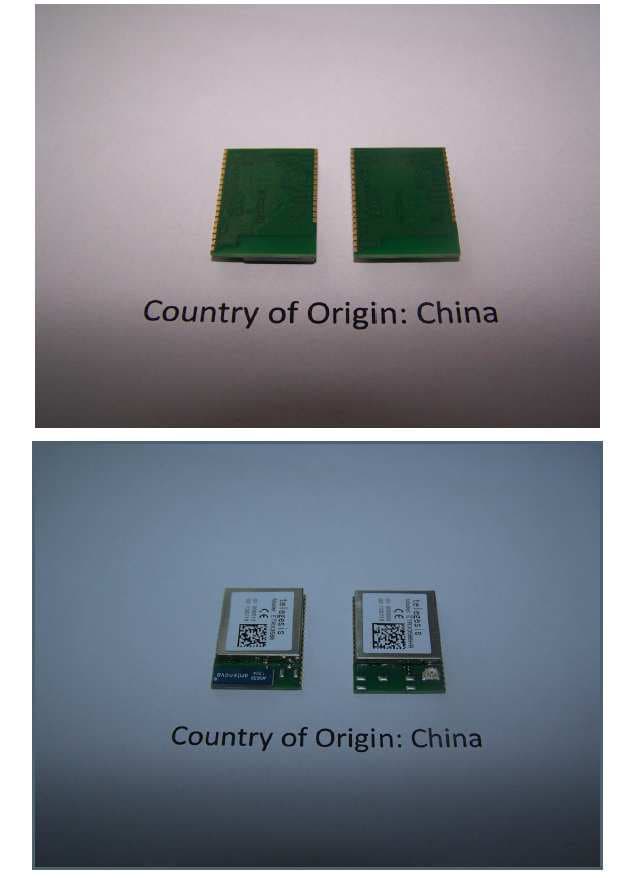
External Photos
Photograph 3 Top view PCB Underside View PCB Photograph 4 Screening can removed Photograph 5 Top View PCB Antenova antenna Underside ViewPCB Antenova Antenna Photograph 6Top View Screening can removed Antenova Antenna
ID Label/Location Info
Telegesis (UK) Limited Label Specification 1 ZigBee Modules ETRX3 Series 3.00 ©2010 Telegesis (UK) Ltd 1.1 ETRX357-LRS The label dimensions are 16.0mm x 14 mm (width x height). The label is suitable for reflow soldering. The font used should be Gill Sans MT for all text, except for the “telegesis” name, which should be displayed using Gill Sans Light MT. Imprint Description Model:ETRX357-LRS Module Order Code. 0000001 Indication for the serial number. Starting at 0000000 for each batch incrementing with each module 090101 Production Date Code in the format YYMMDD, e.g. 090101 01 Indication for batch number Starting at 00 for beta panel, 01 for pilot run, etc... 02 Indication for the hardware revision (should be set to 02 until further notice) FCC ID: S4GEM35XB The FCC ID IC: 8735A-EM35XB The IC ID CE The CE Mark 2D-Barcode Information in the 2D-Barcode are the serial number [6 characters], the Part-Order code [12 characters filled with trailing spaces e.g. “ETRX357-LRS “ instead of “ETRX357-LRS”], identifier for the batch number [2 characters], the identifier for the hardware release [2 characters] and the production date code in the format Year-Month-Day [6 characters], separated by a semicolon. Telegesis (UK) Limited Label Specification 2 ZigBee Modules ETRX3 Series 3.00 ©2010 Telegesis (UK) Ltd 1.2 ETRX351-LRS The label dimensions are 16.0mm x 14 mm (width x height). The label is suitable for reflow soldering. The font used should be Gill Sans MT for all text, except for the “telegesis” name, which should be displayed using Gill Sans Light MT. Imprint Description Model:ETRX351-LRS Module Order Code. 0000001 Indication for the serial number. Starting at 0000000 for each batch incrementing with each module 090101 Production Date Code in the format YYMMDD, e.g. 090101 01 Indication for batch number Starting at 00 for beta panel, 01 for pilot run, etc... 02 Indication for the hardware revision (should be set to 02 until further notice) FCC ID: S4GEM35XB The FCC ID IC: 8735A-EM35XB The IC ID CE The CE Mark 2D-Barcode Information in the 2D-Barcode are the serial number [6 characters], the Part-Order code [12 characters filled with trailing spaces e.g. “ETRX351-LRS “ instead of “ETRX351-LRS”], identifier for the batch number [2 characters], the identifier for the hardware release [2 characters] and the production date code in the format Year-Month-Day [6 characters], separated by a semicolon. Telegesis (UK) Limited Label Specification 3 ZigBee Modules ETRX3 Series 3.00 ©2010 Telegesis (UK) Ltd 1.3 ETRX357HR-LRS The label dimensions are 16.0mm x 14 mm (width x height). The label is suitable for reflow soldering. The font used should be Gill Sans MT for all text, except for the “telegesis” name, which should be displayed using Gill Sans Light MT. Imprint Description Model:ETRX357HR-LRS Module Order Code. 0000001 Indication for the serial number. Starting at 0000000 for each batch incrementing with each module 090101 Production Date Code in the format YYMMDD, e.g. 090101 01 Indication for batch number Starting at 00 for beta panel, 01 for pilot run, etc... 02 Indication for the hardware revision (should be set to 02 until further notice) FCC ID: S4GEM35XB The FCC ID IC: 8735A-EM35XB The IC ID CE The CE Mark 2D-Barcode Information in the 2D-Barcode are the serial number [6 characters], the Part-Order code [12 characters eliminating the ‘-‘ e.g. “ETRX357HRLRS “ instead of “ETRX357HR-LRS”], identifier for the batch number [2 characters], the identifier for the hardware release [2 characters] and the production date code in the format Year- Month-Day [6 characters], separated by a semicolon. Telegesis (UK) Limited Label Specification 4 ZigBee Modules ETRX3 Series 3.00 ©2010 Telegesis (UK) Ltd 1.4 ETRX351HR-LRS The label dimensions are 16.0mm x 14 mm (width x height). The label is suitable for reflow soldering. The font used should be Gill Sans MT for all text, except for the “telegesis” name, which should be displayed using Gill Sans Light MT. Imprint Description Model:ETRX351HR-LRS Module Order Code. 0000001 Indication for the serial number. Starting at 0000000 for each batch incrementing with each module 090101 Production Date Code in the format YYMMDD, e.g. 090101 01 Indication for batch number Starting at 00 for beta panel, 01 for pilot run, etc... 02 Indication for the hardware revision (should be set to 02 until further notice) FCC ID: S4GEM35XB The FCC ID IC: 8735A-EM35XB The IC ID CE The CE Mark 2D-Barcode Information in the 2D-Barcode are the serial number [6 characters], the Part-Order code [12 characters eliminating the ‘-‘ e.g. “ETRX351HRLRS “ instead of “ETRX351HR-LRS”], identifier for the batch number [2 characters], the identifier for the hardware release [2 characters] and the production date code in the format Year- Month-Day [6 characters], separated by a semicolon.
Internal Photos
Photograph 3 Top view PCB Underside View PCB Photograph 4 Screening can removed Photograph 5 Top View PCB Antenova antenna Underside ViewPCB Antenova Antenna Photograph 6Top View Screening can removed Antenova Antenna
Operational Description
ETRX351-LRS and ETRX357-LRS ©2011 Telegesis (UK) Ltd - 12 - ETRX35x-LRS Preliminary Product Manual 4 Hardware Description 24MHz EM35x I/O UART I / O programming 5 JTAG Vcc Vreg RESET RESET Match integrated antenna U.FL socket rf terminal selection, filtering and matching circuitry LDO 1V8 1,8Vdc A/D LDO 1V25 Match FEM Figure 2: Hardware Diagram The ETRX351-LRS and ETRX357-LRS are based on the Ember EM351 and EM357 respectively in addition to a frontend module containing a PA, LNA and RF switch in addition to the RF- Frontend. The EM351 and EM357 are fully integrated 2.4GHz ZigBee transceivers with a 32-bit ARM ® Cortex M3 TM microprocessor, flash and RAM memory, and peripherals. The industry standard serial wire and JTAG programming and debugging interfaces together with the standard ARM system debug components help to streamline any custom software development. In addition to this a number of MAC functions are also implemented in hardware to help maintain the strict timing requirements imposed by the ZigBee and IEEE802.15.4 standards. The new advanced power management features allow faster wakeup from sleep and new power- down modes allow this 3 rd generation module to offer a longer battery life than any 2 nd generation modules on the market. The EM35x has fully integrated voltage regulators for both required 1.8V and 1.25V supply voltages. The voltages are monitored (brown-out detection) and the built in power-on-reset circuit eliminates the need for any external monitoring circuitry. A 32.768kHz watch crystal can be connected externally to pads 3 and 4 in case more accurate timing is required. 4.1 Hardware Interface All GPIO pins of the EM351 or EM357 except PB0 and PC5 are accessible on the module‟s pads. Whether signals are used as general purpose I/Os, or assigned to a peripheral function like ADC is set by the firmware. When using the Telegesis AT Command-set please refer to the AT Command- set manual for this information and when developing custom firmware please refer to the EM35x datasheet. ETRX351-LRS and ETRX357-LRS ©2011 Telegesis (UK) Ltd - 13 - ETRX35x-LRS Preliminary Product Manual 5 Firmware Description The modules will be pre-loaded with a standalone bootloader by Ember, which supports over-the- air bootloading as well as serial bootloading of new firmware. In order to enter the standalone bootloader using a hardware trigger pull PA5 to ground and power-cycle or reset the module. To avoid entering the standalone bootloader unintentionally make sure not to pull this pin down during boot-up unless the resistance to ground is >10kΩ. A pull-up is not required). In addition to the standalone bootloader the modules also contain the current release of the Telegesis AT-style command interface as described in the Telegesis AT command dictionary and the Telegesis user guide. Check www.telegesis.com for updates. Each module comes with a unique 64-bit 802.15.4 identifier which is stored in non-volatile memory. The commands and responses pass through the serial port of the ETRX35x-LRS as ASCII text, so a simple terminal application will usually suffice. Telegesis Terminal is provided as a development tool, but it is not an essential feature. The pre-loaded AT-style command interface firmware is based on the latest EmberZNet meshing stack which implements routers/coordinators as well as (sleepy) end devices. [End devices have no routing responsibility and therefore are allowed to go to sleep, whilst still being able to send and receive messages via a parent router. In addition to a classical (sleepy) end device the module firmware also supports mobile (sleepy) end devices capable of changing their parent quickly whenever they change their position within the network.] A router is typically a mains powered device whilst a sleepy end device (SED) can be battery powered. The module is also able to act as a PAN coordinator and Trust Centre through external host control. The AT style command line supplies all the tools required to set up and manage a ZigBee network by allowing easy access to the low-level functionality of the stack. The Telegesis firmware uses the meshing and self healing EmberZNet PRO stack to overcome many of the limitations of the tree network topology of the ZigBee ® 2006 stack by using the ZigBee PRO feature-set. The Telegesis firmware also allows low-level access to physical parameters such as radio channel and power level. Parameters that define the functionality of the ETRX35x-LRS module and also allow standalone functionality are saved in non-volatile memory organised in so-called S- Registers. The SPI and I2C buses are not supported by the current firmware release, but can be used with custom firmware. 5.1 Custom Firmware For high volume customers the firmware can be customised on request. Customers can use the ETRX35x-LRS module as hardware only and develop application specific firmware based on the EmberZNet stack. In order to develop custom firmware the Ember Insight tool-chain is required. ETRX351-LRS and ETRX357-LRS ©2011 Telegesis (UK) Ltd - 14 - ETRX35x-LRS Preliminary Product Manual 5.2 Boost Mode vs. Normal Mode The Ember EM35x chips support a “boost mode” power setting next to the “normal mode” power setting. The “boost mode” setting increases the sensitivity and output power of the radio transceiver, however with the LRS variants enabling boost mode has no positive effect on neither the output power nor the sensitivity and therefore it is recommended to not use boost mode on this platform. The Telegesis AT Command-set firmware automatically disables boost mode on LRS series modules. Section 11.2lists the requirements for power settings for use of the LRS family in different countries. 5.3 Software Interface Using the default firmware the ETRX35x-LR is controlled using a simple AT-style command interface and (mostly) non-volatile S-Registers. In order to get a full listing of all the available AT- Commands, please refer to the AT command dictionary do…
Text truncated - open the document above for the full version.
RF Exposure Info
RADIO FREQUENCY RADIATION EXPOSURE MPE calculation: Test setup1: EUTMeasuring Receiver Attenuator Formula: S=EIRP/ 4π R 2 S = Power Density (mW/cm 2 ) EIRP = Radiated power (mW) R = distance for body (cm) Calculation: S=57.4/ (4 π 2.2 2 )mW/cm 2 S=0.94 mW/cm 2 Notes: 1.The unit will be mounted at least2.2 cm away from the body. 2.The carrier power EIRP of 57.4mWwas theworst case peak level measured. 3.Antenna Gain of 2dBi stated by manufacturer. Limit The limit of Powerdensity for the General Population/ Uncontrolled Exposure is 1 mW/cm 2 . Result The EUT meet the 1 mW/cm 2 limit.
Test Report
Total number of pages : 82 TRaC Wireless Test Report:TTR-003264WS1 Applicant:Telegesis (UK) Apparatus:ETRX357-LRS& ETRX357HR-LRS Specification(s):CFR47 Part 15.247 July 10 th 2008 FCCID:S4GEM35XB Purpose of Test: Certification Authorised by: : Radio Product Manager Issue Date:28 th January 2011 Authorised Copy Number: PDF Radio Test Report: TTR-003264WUS1 2 Contents Section 1:Introduction3 1.1General3 1.2Tests Requested By4 1.3Manufacturer4 1.4Apparatus Assessed4 1.5Test Result Summary5 1.6Notes Relating To The Assessment6 1.7Deviations from Test Standards6 Section 2:Measurement Uncertainty7 2.1Application of Measurement Uncertainty7 Section 3:Modifications9 3.1Modifications Performed During Assessment9 Appendix A:Formal Emission Test Results10 A1Transmitter Peak Output Power11 A2RF Antenna Conducted Spurious Emissions12 A3Radiated Electric Field Emissions Within The Restricted Bands of 15.20514 A4Power spectral density20 A56 dB Bandwidth21 A6Antenna Gain22 A7Unintentional Radiated Electric Field Emissions - 15.10923 A8Power Line Conducted Emissions27 Appendix B:Supporting Graphical Data29 Appendix C: Additional Test and Sample Details67 Appendix D:Additional Information73 Appendix E:Calculation of the duty cycle correction factor74 Appendix F:Photographs and Figures75 Radio Test Report: TTR-003264WUS1 3 Section 1:Introduction 1.1General This report contains an assessment of an apparatus against Electromagnetic Compatibility Standards based upon tests carried out on samples submitted to the Laboratory. Test performed by: TRaC Telecoms & Radio Unit 1, Pendle Place Skelmersdale, West Lancs, WN8 9PN, UK Telephone:+44 (0) 1695 556666 Fax:+44 (0) 1695 577077 Email:[email protected] Web site:http://www.tracglobal.com Tests performed by:S Hodgkinson Report author:S Hodgkinson This report must not be reproduced except in full without prior written permission from TRaC Telecoms & Radio. Radio Test Report: TTR-003264WUS1 4 1.2Tests Requested By This testing in this report was requested by : Telegesis Abbey Barn Business Centre Abbey Barn Lane High Wycombe Bucks HP10 9QQ United Kingdom 1.3Manufacturer Telegesis Abbey Barn Business Centre Abbey Barn Lane High Wycombe Bucks HP10 9QQ United Kingdom 1.4Apparatus Assessed The following Zigbee device, ETRX357-LRS& ETRX357HR-LRSwereassessed between:13 th - 24 th December 2010 ETRX357-LRShas an integral Antenova Chip antenna ETRX357HR-LRS has a unique antenna connector Radio Test Report: TTR-003264WUS1 5 1.5Test Result Summary Full details of test results are contained within Appendix A. The following table summarises the results of the assessment. The statements relating to compliance with the standards below apply ONLY as qualified in the notes and deviations stated in sections 1.6 to 1.7 of this test report. Full details of test results are contained within Appendix A. The following table summarises the results of the assessment. Test TypeRegulation Measurement standard Result Radiated spurious emissions (Restricted bands) Title 47 of the CFR: Part 15 Subpart (c) 15.247 ANSI C63.10Pass Conducted spurious emissions (Non-restricted bands) Title 47 of the CFR: Part 15 Subpart (c) 15.247 ANSI C63.10Pass 6dB Bandwidth and Channel Spacing Title 47 of the CFR : Part 15 Subpart (c) 15.247(a)(1)(i) ANSI C63.10Pass Conducted Carrier Power Title 47 of the CFR : Part 15 Subpart (c) 15.247(b)(2) ANSI C63.10Pass Unintentional Radiated Spurious Emissions Title 47 of the CFR: Part 15 Subpart (b) 15.109 ANSI C63.10Pass Power Spectral Density Title 47 of the CFR : Part 15 Subpart (c) 15.247(e) ANSI C63.10Pass Abbreviations used in the above table: Mod: Modification CFR: Code of Federal RegulationsANSI: American National Standards Institution REFE: Radiated Electric Field EmissionsPLCE: Power Line Conducted Emissions Radio Test Report: TTR-003264WUS1 6 1.6Notes Relating To The Assessment With regard to this assessment, the following points should be noted: The results contained in this report relate only to the items tested and were obtained in the period between the date of initial receipt of samples and the date of issue of the report. The apparatus was set up and exercised using the configurations, modes of operation and arrangements defined in this report only. Particular operating modes, apparatus monitoring methods and performance criteria required by the standards tested to have been performed except where identified in Section 1.7 of this test report (Deviations from Test Standards). For emissions testing, throughout this test report, “Pass” indicates that the results for the sample as tested were below the specified limit (refer also to Section 2, Measurement Uncertainty). Where relevant, the apparatus was only assessed using the monitoring methods and susceptibility criteria defined in this report. All testing with the exception of testing at the Open Area Test Site was performed under the following environmental conditions: Temperature: 13to 20C Humidity : 40to 45% All dates used in this report are in the format dd/mm/yy. This assessment has been performed in accordance with the requirements of ISO/IEC 17025. 1.7Deviations from Test Standards There were no deviations from the standards tested to. Radio Test Report: TTR-003264WUS1 7 Section 2:Measurement Uncertainty 2.1Application of Measurement Uncertainty The following page contains the measurement uncertainties for measurements All statements of uncertainty are expanded standard uncertainty using a coverage factor of 1.96 to give a 95% confidence where no required test level exists. [1] Adjacent Channel Power Uncertainty in test result = 1.86dB [2] Carrier Power Uncertainty in test result (Equipment - TRLUH120) = 2.18dB Uncertainty in test result (Equipment – TRL05) = 1.08dB Uncertainty in test result (Equipment – TRL479) = 2.48dB [3] Effective Radiated Power Uncertainty in test result = 4.71dB [4] Spurious Emissions Uncertainty in test result = 4.75dB [5] Maximum frequency error Uncertainty in test result…
Text truncated - open the document above for the full version.
Test Setup Photos
Photograph 1 Setup Photograph 2 AC Powerline Conduction
Contact Information
Applicant
Enrico Taddeo(Mr)
Test Firm
Element Materials Technology Warwick LtdMax Leach
Technical Specifications
| # | Rule Parts | Frequency Range | Power Output |
|---|---|---|---|
| 1 | 15C | 2.40 GHz - 2.48 GHz | 57.00 mW |
Other Applications from Silicon Laboratories Finland Oy
S4GEM358X
May 21, 2014ETRX3581, ETRX3582, ETRX3585, ETRX3586, ETRX3587, ETRX3588, ETRX3581HR, ETRX3582HR, ETRX3585HR, ETRX3586HR, ETRX3587HR, ETRX3588HR
Equipment Class
DTS - Digital Transmission System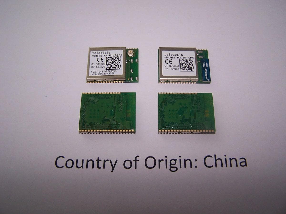
S4GEM358L
May 14, 2014ETRX3581-LRS, ETRX3582-LRS, ETRX3585-LRS, ETRX3586-LRS, ETRX3587-LRS, ETRX3588-LRS, ETRX3581HR-LRS, ETRX3582HR-LRS, ETRX3585HR-LRS, ETRX3586HR-LRS, ETRX3587HR-LRS, ETRX3588HR-LRS
Equipment Class
DTS - Digital Transmission System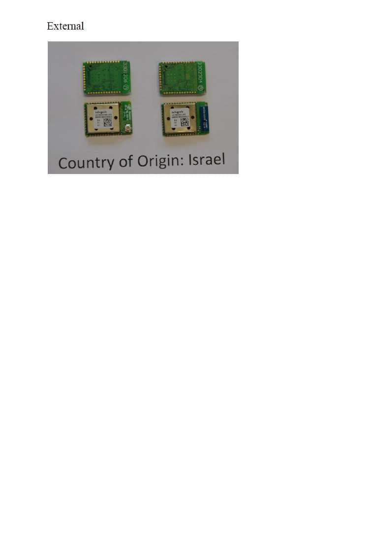
S4GSEM357L
May 06, 2014sETRX357-LRS sETRX357HR-LRS
Equipment Class
DTS - Digital Transmission System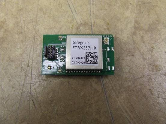
S4GEM35X2
Jul 27, 2010ETRX35x-LR Series Zigbee Modules
Equipment Class
DTS - Digital Transmission System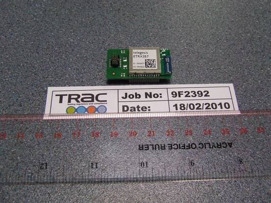
S4GEM35XA
May 05, 2010ETRX35x Series Zigbee Modules
Equipment Class
DTS - Digital Transmission System