S4GETRX1Telegesis ETRX1 Module type TG-ETRX1-PM-01-106
Silicon Laboratories Finland Oy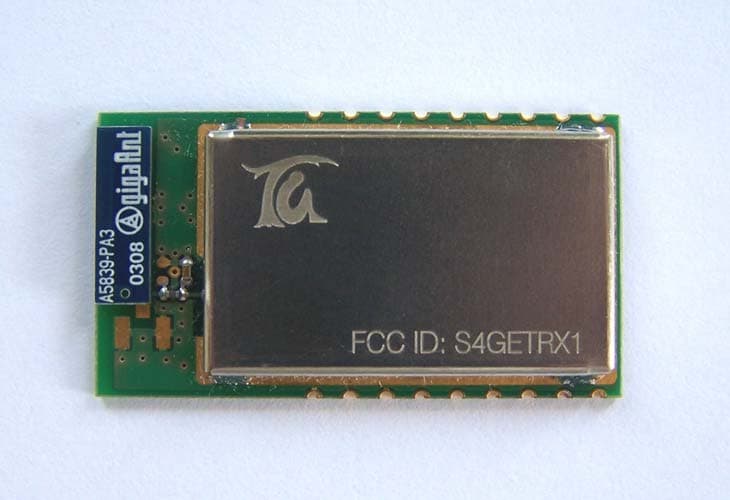
Click to zoom
Application Details
- Equipment Class
- DSS - Part 15 Spread Spectrum Transmitter
- Date of Grant
- Sep 14, 2005
- Application Purpose
- Original Equipment
- Date of Application
- Sep 14, 2005
- Equipment Note
- Telegesis ETRX1 Module type TG-ETRX1-PM-01-106
- Frequency Range
- 2400.00000000 - 2483.50000000
- Country
- Finland
Documents & Files
Document Text
Text extracted from the exhibit documents filed with the FCC. Open a document above to read the original.
Users Manual
Telegesis (UK) Limited TG-ETRX1-PM-01-106 1 ETRX1 Preliminary Product Manual 1.06 TG-ETRX1-PM-01-106 ETRX1 (ZIGBEE™ READY) MODULE PRODUCT MANUAL Telegesis ©2005 Telegesis (UK) Ltd ETRX1 Product Manual (Rev 1.06) Telegesis (UK) Limited TG-ETRX1-PM-01-106 2 ETRX1 Preliminary Product Manual 1.06 Table of Contents 1. INTRODUCTION..........................................................................................................3 2. ETRX1 FUNCTION SUMMARY..................................................................................4 3. PRODUCT APPROVALS............................................................................................5 3.1. CE & FCC Approvals................................................................................................5 3.2. IEEE 802.15.4...........................................................................................................5 3.3. The ZigBee™ Protocol..............................................................................................5 4. FREQUENTLY ASKED QUESTIONS.........................................................................6 5. ABSOLUTE MAXIMUM RATINGS..............................................................................8 6. OPERATING CONDITIONS........................................................................................8 7. ELECTRICAL SPECIFICATIONS...............................................................................9 8. FUNCTIONAL DESCRIPTION..................................................................................10 8.1.Device Pin-out .........................................................................................................11 8.2. Firmware Description..............................................................................................12 8.2.1. Custom Firmware....................................................................................................12 8.3. Interface Description...............................................................................................13 9. AT STYLE COMMAND CONVENTIONS..................................................................14 9.1. Using parameters....................................................................................................14 9.2. AT Command Syntax..............................................................................................15 9.2.1. Module Control & Configuration Commands..........................................................16 9.2.2. Communication Commands....................................................................................20 9.2.3. I/O Commands........................................................................................................30 10. S-REGISTERS...........................................................................................................31 10.1. Standard S-Registers..............................................................................................32 10.2. Extended S-Registers.............................................................................................36 11. LIST OF ERROR CODES..........................................................................................40 12. PHYSICAL DIMENSIONS.........................................................................................41 13. RECOMMENDED FOOTPRINT................................................................................42 14. ORDERING INFORMATION.....................................................................................43 15. TRADEMARKS..........................................................................................................44 16. DISCLAIMER.............................................................................................................44 17. CONTACT INFORMATION.......................................................................................44 18. REFERENCES...........................................................................................................44 ©2005 Telegesis (UK) Ltd ETRX1 Product Manual (Rev 1.06) Telegesis (UK) Limited TG-ETRX1-PM-01-106 3 ETRX1 Preliminary Product Manual 1.06 1. Introduction This document describes the Telegesis ETRX1 wireless meshing Module which has been designed to be integrated into another device and to provide a fast, simple and low cost (ZigBee compatible with adoption of the EmberZstack) interface. The Telegesis ETRX1 Module has been designed to be built into any device and provide a low cost low power radio, ZigBee™ ready meshing solution, using the Ember technologies EmberNet stack. Integration into a wide range of applications is made easy using a simple AT style software interface and advanced hardware design. No RF experience or expertise is required to add this powerful wireless networking capability to your products. The ETRX1 offers fast integration opportunities and the shortest possible time to market for your product. ©2005 Telegesis (UK) Ltd ETRX1 Product Manual (Rev 1.06) Telegesis (UK) Limited TG-ETRX1-PM-01-106 4 ETRX1 Preliminary Product Manual 1.06 2. ETRX1 Function Summary Module Features • Small form factor, SMT module 37.75mm x 20.45mm x 3.4mm • Optional board to board or board to cable plug-in connector • Integrated antenna or alternative Hirose U.FL antenna connector • UART interface for easy communication • IEEE 802.15.4 compliant • Can act as FFD, RFD and Coordinator • Hosts the Atmel Atmega 128L and the Ember EM2420 • 128k flash, 4kbytes EEPROM and 4kbytes of RAM • Up to 8 MIPS processing power • Module comes with standard Telegesis AT style software interface. • Also available without Telegesis AT style interface or with customer specific firmware • 8 general purpose I/O lines and 2 analogue inputs • In System programmable • Optional JTAG Support • Supports 5 different power down modes • Based on the proven EmberNet classic Stack • Full ZigBee™ compliance will be available with the upc…
Text truncated - open the document above for the full version.
External Photos
Telegesis (UK) Limited. – ETRX1 Label Artwork and Positioning. Due to the very small size and dense population of the ETRX1 Module we are unable to fit both the Statement and FCC ID Number on the product. The following text appears in the Product Manual as specified: “This device complies with Part 15 of the FCC Rules. Operation is subject to the following two conditions: (1) this device may not cause harmful interference, and (2) this device must accept any interference received, including interference that may cause undesired operation. The FCC ID for this product is: S4GETRX1 Please Note: The ETRX1 device carries FCC authorization and is marked with the FCC ID Number. Whilst any device into which this authorized module is installed will not normally be required to obtain FCC authorization, this does not preclude the possibility that some other form of authorization or testing may be required for the finished device. When the ETRX1 module is integrated inside another device/product, then the outside surface of that device/product must display a label referring to the enclosed module. This exterior label can use wording such as “Contains Transmitter Module FCC ID: S4GETRX1” or “Contains FCC ID: S4GETRX1” although any similar wording that expresses the same meaning may be used” This FCC ID is applied to the RF shielding can as shown in Figure 1. below. Figure 1.
ID Label/Location Info
RE: FCC Labelling Requirements FCC ID: S4GETRX1 Telegesis (UK) Limited. – ETRX1 Label Artwork and Positioning. Due to the very small size and dense population of the ETRX1 Module we are unable to fit both the Statement and FCC ID Number on the product. The following text appears in the Product Manual as specified: “This device complies with Part 15 of the FCC Rules. Operation is subject to the following two conditions: (1) this device may not cause harmful interference, and (2) this device must accept any interference received, including interference that may cause undesired operation. The FCC ID for this product is: S4GETRX1 Please Note: The ETRX1 device carries FCC authorization and is marked with the FCC ID Number. Whilst any device into which this authorized module is installed will not normally be required to obtain FCC authorization, this does not preclude the possibility that some other form of authorization or testing may be required for the finished device. When the ETRX1 module is integrated inside another device/product, then the outside surface of that device/product must display a label referring to the enclosed module. This exterior label can use wording such as “Contains Transmitter Module FCC ID: S4GETRX1” or “Contains FCC ID: S4GETRX1” although any similar wording that expresses the same meaning may be used” This FCC ID is applied to the RF shielding can as shown in Figure 1. below. Figure 1. Also a label will be placed on the top surface of the ETRX1 Module RF shielding can showing our batch coding identification, as shown in Figure 2. Batch Code: 4mm 2.4mm Figure 2.
Internal Photos
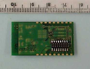
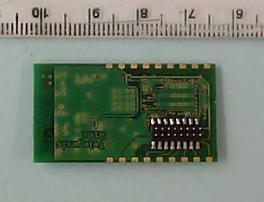
Telegesis (UK) Ltd – ETRX1 Top Can Removed
Test Report
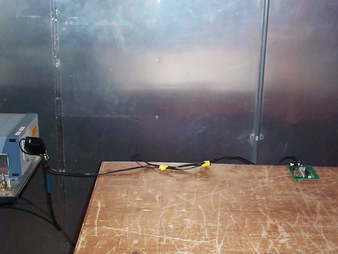
TRL C OMPLIANCE S ERVICES L TD EMC D IVISION M OSS V IEW N IPE L ANE U P H OLLAND W EST L ANCASHIRE WN8 9PY U NITED K INGDOM T ELEPHONE +44 (0)1695 556666 F AX +44 (0)1695 557077 E- MAIL [email protected] www.trlcompliance.com 0728 FS 21805 TEST REPORT NO: RU1171/6423 COPY NO: 2 ISSUE NO: 1 FCC ID: S4GETRX1 REPORT ON THE CERTIFICATION TESTING OF A TELEGESIS (UK) Ltd. ETRX1 Module WITH RESPECT TO THE FCC RULES CFR 47, PART 15.247 JUNE 2005 INTENTIONAL RADIATOR SPECIFICATION ON BEHALF OF TELEGESIS (UK) Ltd. TEST DATE: 16 th – 22 nd June 2005 TESTED BY: J Charters APPROVED BY: P Green Product Manager DATE: 1 st September 2005 Distribution: Copy Nos: 1. TELEGESIS (UK) Ltd. 2. FCC EVALUATION LABORATORIES 3. TRL EMC THIS DOCUMENT MAY BE REPRODUCED ONLY IN ITS ENTIRETY AND WITHOUT CHANGE RU1171/6423 Page 2 of 64 CONTENTS PAGE CERTIFICATE OF CONFORMITY & COMPLIANCE 3 APPLICANT’S SUMMARY 4 EQUIPMENT TEST CONDITIONS 5 TESTS REQUIRED 6 SAMPLE CALCULATIONS 6 TEST RESULTS 7-21 ANNEX PHOTOGRAPHS A PHOTOGRAPH No. 1: Test setup PHOTOGRAPH No. 2: Transmitter front view PHOTOGRAPH No. 3: Transmitter rear view PHOTOGRAPH No. 4: Transmitter lid removed APPLICANT’S SUBMISSION OF DOCUMENTATION LIST B 6dB BAND WIDTH PLOT C BANDEDGE COMPLIANCE D POWER SPECTRAL DENSITY E CONDUCTED SPURIOUS EMISSIONS - TX ON F RADIATED SPURIOUS EMISSIONS – BANDEDGE G RADIATED SPURIOUS EMISSIONS – RX ONLY H POWER LINE CONDUCTED EMISSIONS – TX ON I TEST EQUIPMENT CALIBRATION DETAILS J Notes: 1. Component failure during test YES NO [ ] [X] 2. If Yes, details of failure: 3. The facilities used for the testing of the product contain in this report are FCC Listed. 4. The contents of the attached applicants declarations and other supplied information are not covered by the scope of this laboratory’s UKAS or FCC accreditations’ and is provided in good faith. RU1171/6423 Page 3 of 64 CERTIFICATE OF CONFORMITY & COMPLIANCE FCC IDENTITY: S4GETRX1 PURPOSE OF TEST: Certification TEST SPECIFICATION: FCC RULES CFR 47, Part 15.247 June 2005 TEST RESULT: Compliant to Specification EQUIPMENT UNDER TEST: ETRX1 Module EQUIPMENT SERIAL No: Engineering sample EQUIPMENT TYPE: ETRX1 Module CARRIER EMISSION: 0.00187Watts ANTENNA TYPE: Integral GAIN ANTENNA: 4.4dBi BAND OF OPERATION: 2400MHz – 2483.5MHz CHANNEL SPACING: N/A Wideband channel allocation NUMBER OF CHANNELS: 16 FREQUENCY GENERATION: SAW Resonator [ ] Crystal [ ] Synthesiser [X] MODULATION METHOD: Amplitude [ ] Digital [X] Angle [ ] POWER SOURCE(s): +3.6Vdc TEST DATE(s): 16 th – 22 nd June 2005 ORDER No(s): TG-PO-10197 APPLICANT: TELEGESIS (UK) Ltd. ADDRESS: Marlow Business Centre 84 Station Road Marlow SL7 1NX United Kingdom TESTED BY: J Charters APPROVED BY: P Green Product Manager RU1171/6423 Page 4 of 64 APPLICANT’S SUMMARY EQUIPMENT UNDER TEST (EUT): ETRX1 Module EQUIPMENT TYPE: ETRX1 Module SERIAL NUMBER OF EUT: Engineering Sample PURPOSE OF TEST: Certification TEST SPECIFICATION(s): FCC RULES CFR 47, Part 15.247 June2005 TEST RESULT: COMPLIANT Yes No [X] [ ] APPLICANT’S CATEGORY: MANUFACTURER IMPORTER DISTRIBUTOR TEST HOUSE AGENT [X] [ ] [ ] [ ] [ ] APPLICANT’S ORDER No(s): TG-PO-10197 APPLICANT’S CONTACT PERSON(s): Mr Corin Clifford E-mail address: [email protected] APPLICANT: TELEGESIS (UK) Ltd. ADDRESS: Marlow Business Centre 84 Station Road Marlow SL7 1NX United Kingdom TEL: +44 1628 894347 FAX: +44 1628 894333 MANUFACTURER: TELEGESIS (UK) Ltd. EUT(s) COUNTRY OF ORIGIN: United Kingdom TEST LABORATORY: TRL EMC UKAS ACCREDITATION No: 0728 TEST DATE(s) 16 th – 22 nd June 2005 TEST REPORT No: RU1171/6423 RU1171/6423 Page 5 of 64 EQUIPMENT TEST / EXAMINATIONS REQUIRED 1. TEST/EXAMINATION RULE PART DETECTOR APPLICABILITY Intentional Emission Frequency: 15.247(b) Peak Yes Intentional Emission Field Strength: - - No Intentional Emission Band Occupancy 6dB: 15.247 (a) Peak Yes Intentional Emission ERP (mW): 15.247 (b) Peak Yes Spurious Emissions – Conducted: 15.247 (c) Peak Yes Spurious Emissions – Radiated <1000MHz: 15.209 Quasi Peak Yes (note 1) Spurious Emissions – Radiated >1000MHz: 15.209 Average Yes (note 1) Spectral Power Density 15.247 (e) Peak Yes Spurious Emissions – Power Line TX 15.207 Quasi Peak Average Yes Spurious Emissions – Power Line RX 15.207 Quasi Peak Average Yes Maximum Frequency of Search: 15.33 - Yes Antenna Arrangements Integral: 15.203 - Yes Antenna Arrangements External Connector: 15.204 - Yes Restricted Bands 15.205 - Yes Extrapolation Factor 15.31(f) - Yes Note 1: The manufacturer has stated that this unit is not intended to be operated within 20cm of the body. 3. Emission Designator: 4. Duty Cycle: <100% 5. Transmitter bit or pulse rate and level: 38400Bps 6. Temperatures: Ambient (Tnom) 20 o C 7. Supply Voltages: Vnom 3.6Vdc Note: Vnom voltages are as stated above unless otherwise shown on the test report page Single channel [ ] Two channel [ ] 8. Equipment Category: Multi-channel [X] Narrowband [ ] Wideband [X] 9. Channel Allocation: RU1171/6423 Page 6 of 64 TRANSMITTER TESTS TRANSMITTER 6dB BANDWIDTH – CONDUCTED - PART 15.247(A)(2) Ambient temperature = 20 o C(<1GHz) Relative humidity = 50% (<1GHz), Conditions = Radio Lab Supply voltage = 3.6V Diagram Frequency Channel Measured Bandwidth Limit 2.405MHz Bottom 1.630MHz >500kHz 2.445MHz Middle 1.690MHz >500kHz 2.480MHz Top 1.640MHz >500kHz Notes: 1 For analyser plots see annex C Test Method: 1 The integral antenna was replaced by a temporary antenna connector. 2 The EUT was connected to the analyser via a cable 3 The 6dB bandwidth was recorded with the EUT activity transmitting data. TYPE OF EQUIPMENT MAKER/ SUPPLIER MODEL No SERIAL No TRL No ACTUAL EQUIPMENT USED SPECTRUM ANALYSER ANRITSU MS2665C MT26089 479 X SPECTRUM ANALYSER MARCONI 2386/2380 152076/004 UH120 EUT Analyser TRL479 Cable TRL280 RU1171/6423 Page 7 of 64 TRANSMITTER TESTS TRANSMITTER - MAXIMUM PEAK POWER - CONDUCTED - PART 15.247(B)(3) Ambient temperature = 20 o C(<1GHz) Relative humidity = 50% (<1GHz), Conditions = Radio Lab Supply …
Text truncated - open the document above for the full version.
Contact Information
Applicant
Enrico Taddeo(Mr)
Technical Contact
Test Firm
TRL Compliance LtdJohn Charters
Technical Specifications
| # | Rule Parts | Frequency Range | Power Output | Emission | Tolerance |
|---|---|---|---|---|---|
| 1 | 15C | 2.40 GHz - 2.48 GHz | 2.00 mW | G1W | 40.0000000000 ppm |
Other Applications from Silicon Laboratories Finland Oy
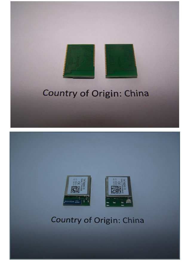
S4GEM358X
May 21, 2014ETRX3581, ETRX3582, ETRX3585, ETRX3586, ETRX3587, ETRX3588, ETRX3581HR, ETRX3582HR, ETRX3585HR, ETRX3586HR, ETRX3587HR, ETRX3588HR
Equipment Class
DTS - Digital Transmission System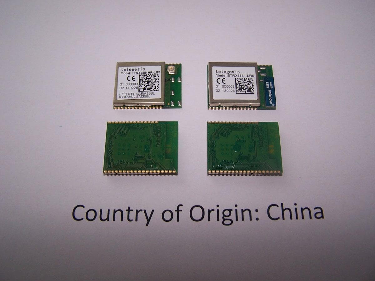
S4GEM358L
May 14, 2014ETRX3581-LRS, ETRX3582-LRS, ETRX3585-LRS, ETRX3586-LRS, ETRX3587-LRS, ETRX3588-LRS, ETRX3581HR-LRS, ETRX3582HR-LRS, ETRX3585HR-LRS, ETRX3586HR-LRS, ETRX3587HR-LRS, ETRX3588HR-LRS
Equipment Class
DTS - Digital Transmission System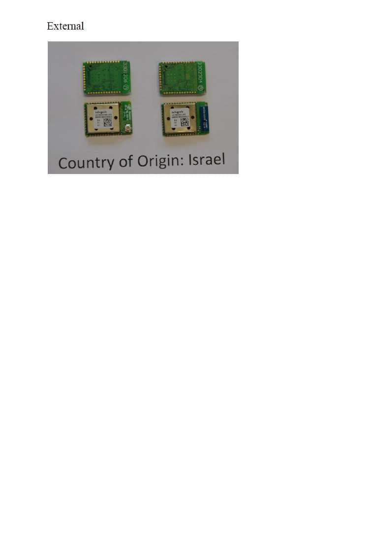
S4GSEM357L
May 06, 2014sETRX357-LRS sETRX357HR-LRS
Equipment Class
DTS - Digital Transmission System
S4GEM35XB
Jan 30, 2011ETRX3 Series Long Range Modules
Equipment Class
DTS - Digital Transmission System
S4GEM35X2
Jul 27, 2010ETRX35x-LR Series Zigbee Modules
Equipment Class
DTS - Digital Transmission System