S4RBST100ERFPA 800MHz CDMA Bidrectional Amplifier
Mobile Communications Inc.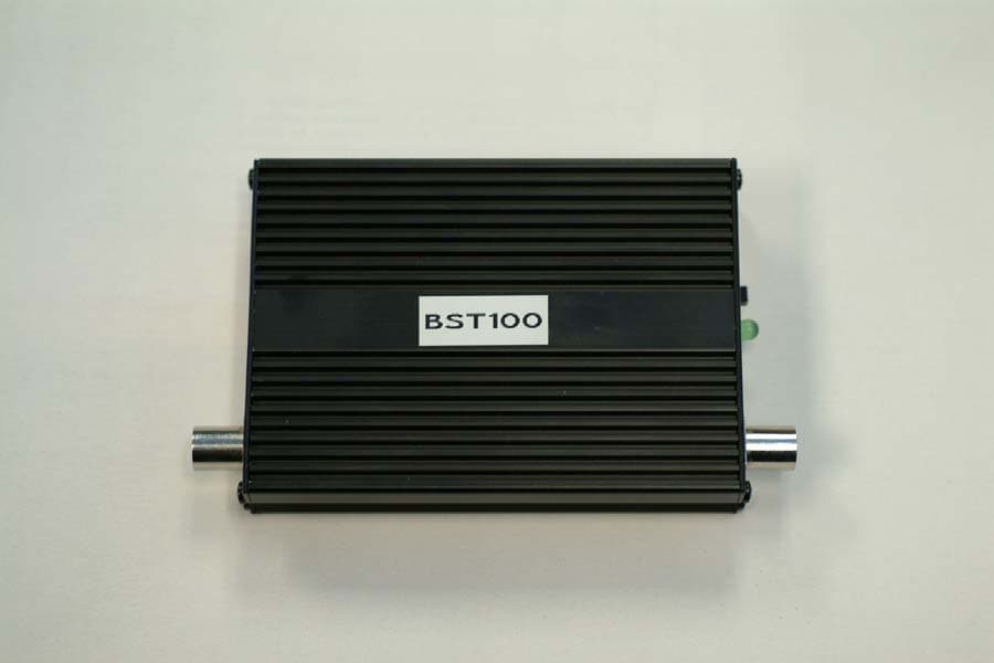
Click to zoom
Application Details
- Equipment Class
- AMP - Amplifier
- Date of Grant
- Apr 06, 2005
- Application Purpose
- Original Equipment
- Date of Application
- Apr 06, 2005
- Equipment Note
- ERFPA 800MHz CDMA Bidrectional Amplifier
- Frequency Range
- 824.00000000 - 849.00000000
- Company
- Mobile Communications Inc.
- Country
- Canada
Documents & Files
Document Text
Text extracted from the exhibit documents filed with the FCC. Open a document above to read the original.
Cover Letter(s)
Mobile Communications 230 Earl Stewart Dr Tel(905) 726-3444 Aurora, Ont. L4G 6V8 Fax(905) 726-4233 ____________________________________________________________________________________________ Feb7/05. Federal Communications Commission Authorization and Evaluation Division Confidentiality Request; FCC ID: SUTBST100 Pursuant to Sections 0.457 ands 0.459 of the Commission’s Rules, the Applicant hereby requests confidential treatment of information accompanying this Application as outlined below: Schematics Block Diagrams Operational Descriptions Parts List The above materials contain trade secrets and proprietary information not customarily released to the public. The public disclosure of these matters might be harmful to the Applicant and provide unjustified benefits to its competitors. The Applicant understands that pursuant to Rule 0.457, disclosure of this Application and all accompanying documentation will not be made before the date of the Grant for this application. Sincerely, Tom Vagenas Director
Parts List/Tune Up Info
Mobile Communications 230 Earl Stewart Dr Tel(905) 726-3444 Aurora, Ont. L4G 6V8 Fax(905) 726-4233 ____________________________________________________________________________________________ Feb 7/05. Timco Engineering Reference: SUTBST100 Dear Sirs, In response to your request regarding tune up procedures for the device bearing the above mentioned FCC type approval number. Please be informed that tuning of these devices are done at the manufacturer’s premises . End users must return the device to MCI Inc. for tuning. Sincerely Tom Vagenas Director
RF Exposure Info
RF exposure exhibit FCC RF Exposure Requirements General information: FCCID: S4RBST100 Modulation: CDMA, GSM, AMPS, TDMA Device category: Mobile / Part 2.1091 Environment: General Population/Uncontrolled Exposure Mobile devices that operate in the Cellular Service authorized under subpart H of part 22 is subject to routine environmental evaluation for RF exposure prior to equipment authorization or use if they operate at frequencies of 1.5 GHz or below and their effective radiated power (ERP) is 1.5 watts (2.46WEIRP) or more, or if they operate at frequencies above 1.5 GHz and their ERP is 3 watts (4.92WEIRP) or more. Otherwise, compliance with the power density limits of 1.1310 is required. Antenna: The device is comprised of an external radio frequency power amplifier with a maximum output power of 3W in the 824-849MHz band, a coaxial cable with a loss of at least 2dB at 824-849MHz, and antennas with a gain of less than 0.5 dBi. This device does not exceed the maximum of 7WERP per Part 22H according to the data and accessories marketed with this amplifier. The maximum antenna gain and cable loss chosen for the calculations overestimate the maximum EIRP, as found for such applications. Typical antennas, of the type listed in the user’s manual, 15” dual band magnet with max gain of 0.5dBi or glass mount antenna with max gain of 0.5dBi. They would yield a 0.5 dBi gain if mounted with a perfect ground. However, they are used in applications where the measurement should be made in free space in the case of glass mount and with an imperfect ground plane for magnet mount. The actual rating for such antenna installed on the roof of a vehicle or a window is lower than 0.5dBi. This device has provisions for operation in a vehicle. Configuration Antenna p/n Type Max. Gain (dBi) Passenger car Any Mag mount 0.5 Truck Any Thru glass 0.5 5/6/2005 Page 1 of 2 FCCID: RFJCB-127 Operating configuration and exposure conditions: The conducted output power is 35.3dBm = 3.4 Watt Vehicle Operation: The maximum antenna gain that can be used is 0.5dBi. A coaxial cable with a loss of at least 2.0dB at 824-849MHz . For such configuration the maximum EIRP is 2.40Watt. MPE Calculation: The minimum separation distance is calculated as follows: The limit for general population/uncontrolled exposure environment is 0.55mW/cm2 for 300<freq.<1,500MHz. Channel Frequency: 836.5MHz required for compliance Rinches8.187= distance in centimeters R20.794= Rinches R 2.54 :=R PoGn⋅() 4π⋅S⋅ () := mW cm 2 S0.558=Gn0.891= gain numeric Gn10 G 10 := 1500 for uncontrolled S f 1500 := gain in dBi GdBd2.15+:= Frequency in MHz f836.5:= antenna gain dBd2.65−:=mWattsPo3400:= Conclusion: The device complies with the MPE requirements by providing a safe separation distance of 20 cm between the antenna, including any radiating structure, and any persons when normally operated. 5/6/2005 Page 2 of 2 FCCID: RFJCB-127
Test Report
TIMCO ENGINEERING INC. 849 NW State Road 45 Newberry, Florida 32669 http://www.timcoengr.com 888.472.2424 F 352.472.2030 email: [email protected] APPLICANT: MOBILE COMMUNICATIONS INC. FCC ID: FCC Test Report Product Name: FCC ID: SUTBST100 Applicant: Mobile Communications Inc. 360 Industrial Parkway South Unit 1 Aurora Ontario L4G 3V7 Canada Date Receipt: JANUARY 27, 2005 Date Tested: FEBRUARY 7, 2005 PLEASE NOTE: THE ATTACHED REPORT SHALL NOT BE REPRODUCED EXCEPT IN FULL WITHOUT THE WRITTEN APPROVAL OF TIMCO ENGINEERING, INC. SUTBST100 REPORT #: M\MOBILE_SUT\166AUT5\166AUT5TestReport.doc COVER LETTER TIMCO ENGINEERING INC. 849 NW State Road 45 Newberry, Florida 32669 http://www.timcoengr.com 888.472.2424 F 352.472.2030 email: [email protected] APPLICANT: MOBILE COMMUNICATIONS INC. FCC ID: TABLE OF CONTENTS LIST TEST REPORT: PAGE 1............COMPLIANCE STATEMENT PAGE 2............GENERAL INFORMATION & TECHNICAL DESCRIPTION PAGE 3............TECHNICAL DESCRIPTION CONTINUED RF POWER OUTPUT PAGE 4-6..........CARRIER POWER CDMA2000 / CDMA1 PAGE 7-9..........OCCUPIED BANDWIDTH CDMA2000 / CMDA1 PAGE 10...........INPUT/OUTPUT MODULATED AMPLITUDE COMPARISON CDMA2000 PAGE 11-15........OUT OF BAND EMISSIONS & BANDEDGE COMPLIANCE PAGE 16-17........SPURIOUS EMISSIONS AT ANTENNA TERMINALS PAGE 18...........METHOD OF MEASURING SPURIOUS EMISSIONS AT ANTENNA TERMINALS PAGE 19-21........FIELD STRENGTH OF SPURIOUS EMISSIONS PAGE 22...........METHOD OF MEASURING RADIATED SPURIOUS EMISSIONS PAGE 23-29........INPUT/OUTPUT MODULATED AMPLITUDE COMPARISON PAGE 30-35........EQUIPMENT LIST EXHIBITS CONTAINING: CONFIDENTIALITY LETTER BLOCK DIAGRAM SCHEMATIC PARTS LIST USERS MANUAL LABEL SAMPLE LABEL LOCATION EXTERNAL PHOTOGRAPHS INTERNAL PHOTOGRAPHS TUNING PROCEDURE OPERATIONAL DESCRIPTION TEST SET UP PHOTOGRAPH RF EXPOSURE STATEMENT SUTBST100 REPORT #: M\MOBILE_SUT\166AUT5\166AUT5TestReport.doc TABLE OF CONTENTS TIMCO ENGINEERING INC. 849 NW State Road 45 Newberry, Florida 32669 http://www.timcoengr.com 888.472.2424 F 352.472.2030 email: [email protected] APPLICANT: MOBILE COMMUNICATIONS INC. FCC ID: COMPLIANCE STATEMENT: This equipment has been tested in accordance with the standards identified in this test report. To the best of my knowledge and belief, these tests were performed using the measurement procedures described in this report and demonstrate that the equipment complies with the appropriate standards. No modifications were made to the equipment during testing in order to demonstrate compliance with these standards. I attest that the necessary measurements were made, under my supervision, at TIMCO ENGINEERING, INC. located at 849 N.W. State Road 45, Newberry, Florida 32669. Authorized Signatory Name: Mario de Aranzeta Signature: Date: 02/07/05 Test engineer name: Joe Scoglio Signature: <on file> Date: 02/07/05 SUTBST100 REPORT #: M\MOBILE_SUT\166AUT5\166AUT5TestReport.doc Page 1 of 35 TIMCO ENGINEERING INC. 849 NW State Road 45 Newberry, Florida 32669 http://www.timcoengr.com 888.472.2424 F 352.472.2030 email: [email protected] APPLICANT: MOBILE COMMUNICATIONS INC. FCC ID: GENERAL INFORMATION REQUIRED FOR TYPE ACCEPTANCE 2.1033(c)(1)(2) Mobile Communications Inc. will manufacture the FCCID: SUTBST100 EXTERNAL RF POWER AMPLIFIER in quantity, for use under FCC RULES PART 22H. Mobile Communications Inc. 360 Industrial Parkway South Unit 1 Aurora, Ontario L4G 3V7 Canada 2.1033(c) TECHNICAL DESCRIPTION 2.1033(c)(3) Instruction book. A draft copy of the instruction manual is included in the exhibits. 2.1033(c) (4) Type of Emission: F9W (CDMA), GXW (GSM), F1D (AMPS), and DXW for (TDMA/NADC) 2.1033(c)(5) Frequency Range: 824 - 849 MHz 869 – 894 MHz 2.1033(c)(6) There are no user power controls. 2.1033(c)(7) Maximum Output Power rating per rules parts: Part 22.913: Mobile unit max power is 7WERP 2.1033(c)(8) DC Voltages and Current into Final Amplifier: POWER INPUT: FINAL AMPLIFIER ONLY INPUT POWER: (12 VDC)(1 A) = 12 Watts 2.1033(c)(9) Tune-up procedure. The tune-up procedure is included in the exhibits. 2.1033(c)(10) Complete Circuit Diagrams: The circuit diagram and block diagram are included in the exhibits. Description of all circuitry and devices provided for determining and stabilizing frequency is included in the exhibits. 2.1033(c)(11) A photograph or drawing of the equipment identification label is shown in the exhibits. 2.1033(c)(12) Photographs of the equipment of sufficient clarity to reveal equipment construction and layout and label location are shown in the exhibits. SUTBST100 REPORT #: M\MOBILE_SUT\166AUT5\166AUT5TestReport.doc Page 2 of 35 TIMCO ENGINEERING INC. 849 NW State Road 45 Newberry, Florida 32669 http://www.timcoengr.com 888.472.2424 F 352.472.2030 email: [email protected] APPLICANT: MOBILE COMMUNICATIONS INC. FCC ID: 2.1033(c)(13) For equipment employing digital modulation, a detail description of the modulation technique: N/A as this device is an amplifier 2.1033(c)(14) The data required for 2.1046 through 2.1057 is submitted below. 2.1046(a) RF POWER OUTPUT RF power is measured by connecting a 50 ohm, resistive wattmeter to the RF output connector. With a nominal voltage of 12 VDC using a laboratory power supply , and the transmitter properly adjusted the RF output measures: UPLINK RF OUTPUT POWER: 3 WATTS Frequency (MHz) SA Reading (dBm) Cable Loss (dB) Attenuation (dB) Result (dBm) Output Power (W) Limit (W) ERP 824 35.04 CorrectedCorrected 35.04 3.2 7 836.5 35.29 CorrectedCorrected 35.29 3.4 7 849 34.75 CorrectedCorrected 34.75 3.0 7 DOWNLINK RF OUTPUT POWER: Frequency (MHz) Cable Loss (dB) Attenuation (dB) Result (dBm) 869 Corrected Corrected 6.88 881.5 Corrected Corrected 9.36 894 Corrected Corrected 8.95 In Out Device Under Test 20dB Attenuator Power Supply External preampli fier Vector Signal generator 50ohm Power Meter SUTBST100 REPORT #: M\MOBILE_SUT\166AUT5\166AUT5TestReport.doc Page 3 of 35 TIMCO ENGINEERING INC. 849 NW State Road 45 Newberry, Florida 32669 http://www.…
Text truncated - open the document above for the full version.
Contact Information
Applicant
Tom Vagenas(Director of Operations)
Test Firm
Timco Engineering, Inc.S Sanders
Technical Specifications
| # | Rule Parts | Frequency Range | Power Output | Emission | Tolerance |
|---|---|---|---|---|---|
| 4 | 22H | 824 MHz - 849 MHz | 3 W | DXW | Amp |
Other Applications from Mobile Communications Inc.

S4R-TBGP
Jul 27, 2015Tablet PC
Equipment Class
PCB - PCS Licensed Transmitter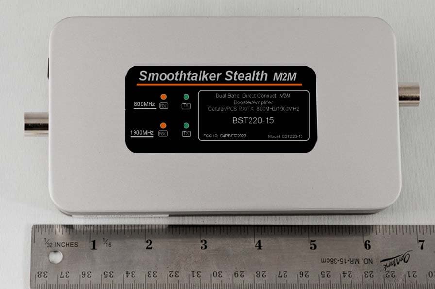
S4RBST22023
Oct 05, 2014Consumer Wide-band Coupling Booster
Equipment Class
B2W - Part 20 Wideband Consumer Booster (CMRS)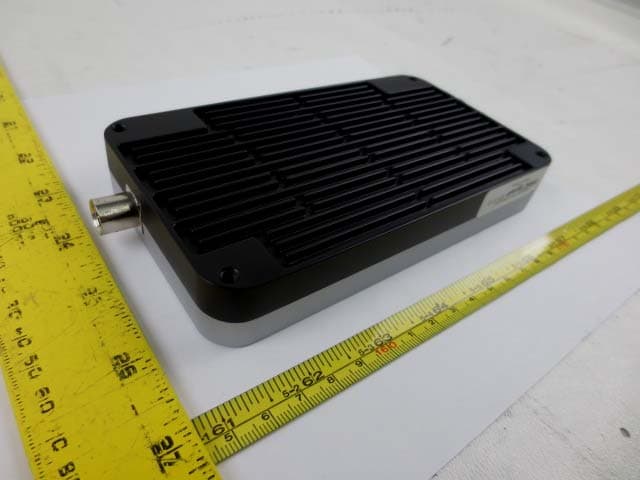
S4RBRBUZ81975
Oct 02, 2014Consumer Wide-band Bi-directional Booster
Equipment Class
B2W - Part 20 Wideband Consumer Booster (CMRS)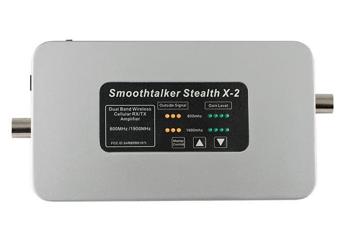
S4RBRB81975
May 12, 2014Consumer Wideband Bi-Directional Booster
Equipment Class
B2W - Part 20 Wideband Consumer Booster (CMRS)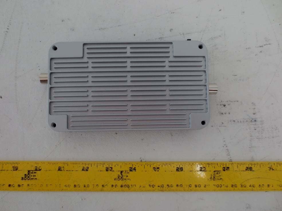
S4RBRM22050
Mar 24, 2014Consumer Wideband Bi-Directional Booster
Equipment Class
B2W - Part 20 Wideband Consumer Booster (CMRS)