S4RBST22023Consumer Wide-band Coupling Booster
Mobile Communications Inc.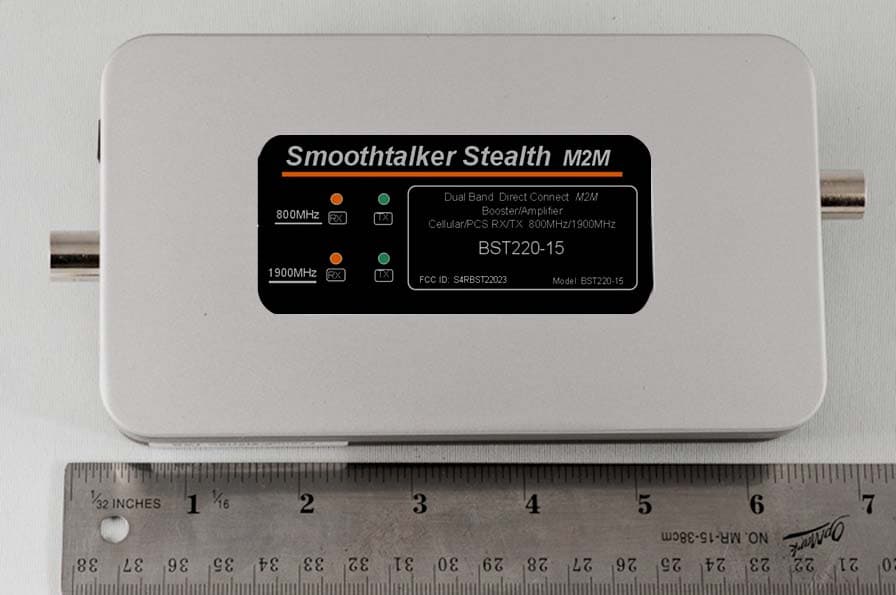
Click to zoom
Application Details
- Equipment Class
- B2W - Part 20 Wideband Consumer Booster (CMRS)
- Date of Grant
- Oct 05, 2014
- Application Purpose
- Original Equipment
- Date of Application
- Sep 23, 2014
- Equipment Note
- Consumer Wide-band Coupling Booster
- Frequency Range
- 1930.00000000 - 1990.00000000
- Company
- Mobile Communications Inc.
- Country
- Canada
Documents & Files
Document Text
Text extracted from the exhibit documents filed with the FCC. Open a document above to read the original.
Users Manual
MOBILE M2M User Manual This is a CONSUMER device. BEFORE USE, you MUST REGISTER THIS DEVICE with your wireless provider and have your provider’s consent. Most wireless providers consent to the use of signal boosters. Some providers may not consent to the use of this device on their network. If you are unsure, contact your provider. You MUST operate this device with approved antennas and cables as specified by the manufacturer. Antennas MUST be installed at least 20 cm (8 inches) from any person. You MUST cease operating this device immediately if requested by the FCC or a licensed wireless service provider. WARNING. E911 location information may not be provided or may be inaccurate for calls served by using this device. Warranty: 3 Year on manufacturing defects. Does not include misuse or customer damage. Original Bill of Sale is required for all Warranty Claims All parts shown may or may not be included depending on the product part number purchased 3 ft Cable to connect to cellular device cellular booster outside antenna 12 volt install type12 volt socket plug type120 volt AC/DC To comply with FCC rules, this booster must only be operated with cables, antennas and coupling devices that have been approved for use with this equipment For specifications of any of the Smoothalker FCC approved part numbers listed below visit smoothtalker.com APPROVED EQUIPMENT LIST Extension Cables Magnetic base Antennas Thru-hole Antennas ACX100 ACX900 SEMRCBXmaXfe10 SEMRCBXmaXfe20 SEMRCBXmaXfe30 SEMRCBXmaXfe40 SEMRCBXmaXfe50 SEMRCBXmaXfe60 SEMiniX1 SEM2M series SEM11M series SEM14M series SEM2LGM series SEM11LGM series SEM14LGM series SEM26LGM series SEM2LGML series SEM11LGML series SEM14LGML series SEM26LGML series CONTENTS SEM2TH series SEM11TH series SEM14TH series SEM26TH series SEM2THL series SEM11THL series SEM14THL series SEM26THL series Directional Antennas SEMD1 series SEMDA2 series Fig. 1Fig. 2 Operational Bands 800MHz Cellular 1900MHz PCS Maximum Radiated Power (EIRP) 29.9 dBm 29.9 dBm Maximum Rated Power (conducted) 29 dBm 28 dBm Gain 15 dB Impedance (input/ouput) 50 Ohms Power Supply 12 Volt DC or 120 Volt AC/DC Operating Temperature -32C to +85C Antenna Connectors MCT Male Dimensions 6.25x3.5x1.125 inches Weight 1.0 Lb SPECIFICATIONS 1) Installation & Assembly: Connect the cellular devise, the outside antenna and power supply to the booster. Please make sure to connect each item to the correct ports as indicated on the booster. 2) Placement Connect the booster as shown in Fig. 1 and Fig. 2 Important: Use only the power supply included with the booster. Connecting any other power supply at any time will result in damage to the booster and will void the warranty. Do not turn on the power switch until ALL cables have been screwed or plugged into the booster or you can cause damage to the booster. Orange LED Lights (RX): There are two orange LED lights, one for the 800Mhz cellular band and one for the 1900Mhz PCS band. LED ON state indicates that the RX (Receive Signal) function of the band is functioning normally. LED Off state indicates that the band is shut down. Green LED Lights (TX): There are two Green LED lights, one for the 800Mhz cellular band and one for the 1900Mhz PCS band. Solid ON state indicates that the TX (Transmit Signal) function of the indicated band is on and is at maximum gain. A Flashing Green LED indicates gain reduction in the indicated band. Each flash equals 3db reduction in gain. One flash represents a 3dB reduction, two flashes represents a 6dB reduction etc. until the total gain of the booster has been suppressed. Causes of Flashing Green LED Lights: 1-If the outside antenna is located too close to the internal antenna or phone holder the booster will reduce its gain in order to suppress any oscillation (feedback loop) and the Green LED will flash. To achieve higer gain or max gain further separatiion of the inside and outside antennas is required. 2-If the booster is close to a cellular tower (strong cell tower signal) it will automatically reduce its gain to protect the network. This condition will change as the booster approaches or leaves a cellular tower. Understanding the lights NOTE: It is normal for the booster to be quite warm while the phone is in use state. TECH SUPPORT: www.smoothtalker.com
Users Manual
MOBILE CX1 User Manual This is a CONSUMER device. BEFORE USE, you MUST REGISTER THIS DEVICE with your wireless provider and have your provider’s consent. Most wireless providers consent to the use of signal boosters. Some providers may not consent to the use of this device on their network. If you are unsure, contact your provider. You MUST operate this device with approved antennas and cables as specified by the manufacturer. Antennas MUST be installed at least 20 cm (8 inches) from any person. You MUST cease operating this device immediately if requested by the FCC or a licensed wireless service provider. WARNING. E911 location information may not be provided or may be inaccurate for calls served by using this device. Warranty: 3 Year on manufacturing defects. Does not include misuse or customer damage. Original Bill of Sale is required for all Warranty Claims All parts shown may or may not be included depending on the product part number purchased Coupling antenna (for use only with cellular modems and data only devices cellular booster outside antenna cell phone cradle 12 volt install type12 volt socket plug type120 volt AC/DC To comply with FCC rules, this booster must only be operated with cables, antennas and coupling devices that have been approved for use with this equipment For specifications of any of the Smoothalker FCC approved part numbers listed below visit smoothtalker.com APPROVED EQUIPMENT LIST Coupling holders Extension Cables Magnetic base Antennas Thru-hole Antennas BTH series ACX100 ACX900 SEMRCBXmaXfe10 SEMRCBXmaXfe20 SEMRCBXmaXfe30 SEMRCBXmaXfe40 SEMRCBXmaXfe50 SEMRCBXmaXfe60 Coupling antennas SEMRP1X SEMRP1XL SEMiniX1 SEM2M series SEM11M series SEM14M series SEM2LGM series SEM11LGM series SEM14LGM series SEM26LGM series SEM2LGML series SEM11LGML series SEM14LGML series SEM26LGML series CONTENTS SEM2TH series SEM11TH series SEM14TH series SEM26TH series SEM2THL series SEM11THL series SEM14THL series SEM26THL series Directional Antennas SEMD1 series SEMDA2 series Fig. 1Fig. 2 Operational Bands 800MHz Cellular 1900MHz PCS Maximum Radiated Power (EIRP) 29.9 dBm 29.9 dBm Maximum Rated Power (conducted) 29 dBm 28 dBm Gain 23 dB Impedance (input/ouput) 50 Ohms Power Supply 12 Volt DC or 120 Volt AC/DC Operating Temperature -32C to +85C Antenna Connectors MCT Male Dimensions 6.25x3.5x1.125 inches Weight 1.0 Lb SPECIFICATIONS 1) Installation & Assembly: Connect the inside antenna or cell phone holder, the outside antenna and power supply to the booster. Please make sure to connect each item to the correct ports as indicated on the booster. 2) Placement Connect the booster as shown in Fig. 1 and Fig. 2 Important: Use only the power supply included with the booster. Connecting any other power supply at any time will result in damage to the booster and will void the warranty. Do not turn on the power switch until ALL cables have been screwed or plugged into the booster or you can cause damage to the booster. Orange LED Lights (RX): There are two orange LED lights, one for the 800Mhz cellular band and one for the 1900Mhz PCS band. LED ON state indicates that the RX (Receive Signal) function of the band is functioning normally. LED Off state indicates that the band is shut down. Green LED Lights (TX): There are two Green LED lights, one for the 800Mhz cellular band and one for the 1900Mhz PCS band. Solid ON state indicates that the TX (Transmit Signal) function of the indicated band is on and is at maximum gain. A Flashing Green LED indicates gain reduction in the indicated band. Each flash equals 3db reduction in gain. One flash represents a 3dB reduction, two flashes represents a 6dB reduction etc. until the total gain of the booster has been suppressed. Causes of Flashing Green LED Lights: 1-If the outside antenna is located too close to the internal antenna or phone holder the booster will reduce its gain in order to suppress any oscillation (feedback loop) and the Green LED will flash. To achieve higer gain or max gain further separatiion of the inside and outside antennas is required. 2-If the booster is close to a cellular tower (strong cell tower signal) it will automatically reduce its gain to protect the network. This condition will change as the booster approaches or leaves a cellular tower. Understanding the lights NOTE: It is normal for the booster to be quite warm while the phone is in use state. TECH SUPPORT: www.smoothtalker.com
Attestation Statements
Mobile Communications Inc. 230 Earl Stewart Drive Aurora, Ont. Canada L4G 6V8 Phone:(905)726-3444 Fax:(905)726-4233 July 29, 2014 Federal Communications Commission Office of Engineering and Technology 445 12th Street, S.W. Washington, D.C. 20554 Device: Wideband Consumer Wireless Booster FCC ID: S4RBST22023 Subject: KDB 935210 SIGNAL BOOSTERS CERTIFICATION REQUIREMENTS 3 Consumer Signal Booster Specifics Section: (c) Attestation non-confidential (1) Does not apply to wideband consumer booster (2) NPS and other compliance/safeguard features have been implemented (3) NPS and other compliance/safeguard features are defaulted to be “On” (in operation) (4) NPS and other compliance/safeguard features can not be field reconfigured, disabled or removed (5) Consumer booster is not user programmable, does not need fine tuning or adjustment, does not require professional installation (6) Future software upgrade will not cause non-compliance Sincerely Tom Vagenas Director
Cover Letter(s)
Mobile Communications Inc. 230 Earl Stewart Drive Aurora, Ont. Canada L4G 6V8 Tel: (905)726-3444 Fax:(905)726-4233 FCC Authorization July 29, 2014 FEDERAL COMMUNICATIONS COMMISSION Authorization and Evaluation Division 7435 Oakland Mills Road Columbia, MD 21046 Subject: Agent Authorization for the following project: FCC ID: S4RBST22023 Product Description: Consumer wide-band bi-directional fixed booster To whom it may concern: We, Mobile Communications Inc., the undersigned, Hereby authorizes Bay Area Compliance Laboratories Corporation to act on its behalf in all matters relating to application for Equipment authorization, including the signing of all documents relating to these matters. All acts carried out by Bay Area Compliance Laboratory Corporation on our behalf shall have the same effect as our own action. We, the undersigned, hereby certify that we are not subject to a denial of federal benefits, that includes FCC benefits, pursuant to Section 5301 of the Anti-Drug Abuse Act of 1988, 21 U.S.C. 853(a). This authorization is valid until further written notice from the applicant. Sincerely, Tom Vagenas Director ASO QA-FR-170-A
Cover Letter(s)
Mobile Communications Inc. 230 Earl Stewart Drive Aurora, Ont. Canada L4G 6V8 Tel: (905)726-3444 Fax:(905)726-4233 FCC Confidential Authorization July 29, 2014 FEDERAL COMMUNICATIONS COMMISSION Authorization and Evaluation Division 7435 Oakland Mills Road Columbia, MD 21046 Subject: Confidentiality Request regarding application for certification of FCC ID: S4RBBST22023 In accordance with Sections 0.457 and 0.459 of the Commission’s Rules, Mobile Communications Inc., hereby requests long-term confidential treatment of information accompanying this application as outlined below: •Block Diagram •Schematics •Operational Description As well as short-term confidential treatment of information accompanying this application as outlined below: •Internal Photos •User’s Manual •External Photos The above materials contain proprietary and confidential information not customarily released to the public. The public disclosure of these materials provides unjustified benefits to its competitors in the market. Sincerely, Tom Vagenas, Director ASO QA-FR-172-A
Cover Letter(s)
Mobile Communications Inc. 230 Earl Stewart Drive Aurora, Ont. Canada L4G 6V8 Tel: (905)726-3444 Fax:(905)726-4233 DECLARATION OF SIMILARITY September 2, 2014 To: Bay Area Compliance Laboratories Corp. 1274 Anvilwood Ave. Sunnyvale, CA 94089 Phone: 408-732-9162, Fax: 408-732-9164 http://www.baclcorp.com Ref: S4RBST22023 Dear Sir or Madam: We, Mobile Communications Inc., hereby declare that product: Consumer Wide-band, bi- directional Booster, model: BST22015 are electrically identical with the same electromagnetic emissions and electromagnetic compatibility characteristics as model: BST22023 tested by BACL. A description of the differences between the tested model and those that are declared similar are as follows: Model: BST22015 is a 15 db gain direct connect booster Model: BST22023 is a 23 db gain coupling connect booster Please contact me should there be need for any additional clarification or information. Sincerely, Tom Vagenas Director ASO Per: Mobile Communications Inc. 230 Earl Stewart Dr. L4G 6V8 Aurora, Ontario Canada BACL-NF0028-A
External Photos
Mobile Communications, Inc. FCC ID: S4RBST22023 Report Number: R1408149-2224 Page 18 of 21 FCC Part 22H/24E Test Report 8 Exhibit C - EUT Photographs 8.1 EUT Top View (BST220-23) 8.2 EUT Top View (BST220-15) Mobile Communications, Inc. FCC ID: S4RBST22023 Report Number: R1408149-2224 Page 19 of 21 FCC Part 22H/24E Test Report 8.3 EUT - Bottom View 8.4 EUT - Side View
ID Label/Location Info
Mobile Communications Inc. FCC ID: S4RBST22023 DUT labels Report Number: BST22023-72914 Page 1 of 2FCC Part 20.21 Mobile Communications Inc. FCC ID: S4RBST22023 Warning label Label location: Report Number: BST22023-72914 Page 2 of 2FCC Part 20.21 This is a CONSUMER device BEFORE USE, you MUST REGISTER THIS DEVICE with your wireless provider and have your provider's consent. Most wireless providers consent to the use of signal boosters. Some providers may not consent to the use of this device on their network. If you are unsure, contact your provider. You MUST operate this device with approved antennas and cables as specified by the manufacturer. Antennas MUST be installed at least 20 cm (8 inches) from any person. You MUST cease operating this device immediately if requested by the FCC or a licensed wireless service provider. WARNING. E911 location information may not be provided or may be inaccurate for calls served by using this device.
Internal Photos
Mobile Communications, Inc. FCC ID: S4RBST22023 Report Number: R1408149-2224 Page 20 of 21 FCC Part 22H/24E Test Report 8.5 EUT – Open Chassis View 8.6 EUT – PCB Top View Mobile Communications, Inc. FCC ID: S4RBST22023 Report Number: R1408149-2224 Page 21 of 21 FCC Part 22H/24E Test Report 8.7 EUT – PCB Bottom View 8.8 EUT – AC/DC Adapter --- END OF REPORT ---
Parts List/Tune Up Info
Mobile Communications Inc. 230 Earl Stewart Drive Aurora, Ont. Canada L4G 6V8 Tel: (905)726-3444 Fax:(905)726-4233 July 29, 2014 To: Bay Area Compliance Laboratories Corp. 1274 Anvilwood Avenue Sunnyvale, CA 94089 Subject: Tune-up procedure Reference: S4RBST22023 Dear Sir/Madam, This devise does not require any tune-up procedure. Sincerely, Tom Vagenas Director ASO
RF Exposure Info
Mobile Communications, Inc. FCC ID: S4RBST22023 Report Number: R1408149-2224 Page 9 of 21 FCC Part 22H/24E Test Report 4 FCC §1.1310 & §2.1091 - RF Exposure Information 4.1 Applicable Standards According to §1.1310 and §2.1091 (Mobile Devices) RF exposure is calculated. Limits for General Population/Uncontrolled Exposure Frequency Range (MHz) Electric Field Strength (V/m) Magnetic Field Strength (A/m) Power Density (mW/cm 2 ) Averaging Time (minute) Limits for General Population/Uncontrolled Exposure 0.3-1.34 614 1.63 *(100) 30 1.34-30 824/f 2.19/f *(180/f 2 ) 30 30-300 27.5 0.073 0.2 30 300-1500 / / f/1500 30 1500-100,000 / / 1.0 30 Note: f = frequency in MHz * = Plane-wave equivalent power density 4.2 MPE Prediction Predication of MPE limit at a given distance, Equation from OET Bulletin 65, Edition 97-01 S = PG/4R² Where: S = power density P = power input to antenna G = power gain of the antenna in the direction of interest relative to an isotropic radiator R = distance to the center of radiation of the antenna Cellular Band Uplink: Maximum output power at antenna input terminal (dBm): 29.0 Maximum output power at antenna input terminal (mW): 794.332 Prediction distance (cm): 20 Prediction frequency (MHz): 836 Maximum Antenna Net Gain (dBi): 1.0 Maximum Antenna Net Gain (numeric): 1.259 Power density at predication frequency and distance (mW/cm 2 ): 0.199 MPE limit for uncontrolled exposure at predication frequency (mW/cm 2 ): 0.557 Mobile Communications, Inc. FCC ID: S4RBST22023 Report Number: R1408149-2224 Page 10 of 21 FCC Part 22H/24E Test Report Downlink: Maximum output power at antenna input terminal (dBm): -26.3 Maximum output power at antenna input terminal (mW): 0.0023 Prediction distance (cm): 20 Prediction frequency (MHz): 881 Maximum Antenna Net Gain (dBi): 8.0 Maximum Antenna Net Gain (numeric): 6.31 Power density at predication frequency and distance (mW/cm 2 ): 0.000003 MPE limit for uncontrolled exposure at predication frequency (mW/cm 2 ): 0.587 PCS Band Uplink: Maximum output power at antenna input terminal (dBm): 28.0 Maximum output power at antenna input terminal (mW): 630.9573 Prediction distance (cm): 20 Prediction frequency (MHz): 1893.6 Maximum Antenna Net Gain (dBi): 1.0 Maximum Antenna Net Gain (numeric): 1.25 Power density at predication frequency and distance (mW/cm 2 ): 0.1580 MPE limit for uncontrolled exposure at predication frequency (mW/cm 2 ): 1.0 Downlink: Maximum output power at antenna input terminal (dBm): -29.7 Maximum output power at antenna input terminal (mW): 0.0011 Prediction distance (cm): 20 Prediction frequency (MHz): 1960 Maximum Antenna Net Gain (dBi): 8.0 Maximum Antenna Net Gain (numeric): 6.31 Power density at predication frequency and distance (mW/cm 2 ): 0.000001 MPE limit for uncontrolled exposure at predication frequency (mW/cm 2 ): 1.0 4.3 MPR Result The device complies with the MPE requirements by providing a safe separation distance of 20 cm between the antenna, including any radiating structure. The proposed RF exposure safety information has been included in the User’s Manual.
Test Report
Mobile Communications Inc. FCC ID: S4RBST22023 Report Number: BST22023-72914 Page 1 of 72 FCC Part 20.21 FCC TEST REPORT FCC Rules & Regulations Part 20.21 For: Mobile Communications, Inc 230 Earl Stewart Dr., Aurora, ON, Canada L4G6V8 FCC ID: S4RBST22023 Report Type: Original Report Product Type: Consumer wide-band bi-directional coupling booster Test Engineer: Roman Gurvich Report Number: BST22023-72914 Report Date: July 29, 2014 Test Procedure: As specified in KDB publication 935210 D03 with FCC permission dated 9/30/2013 to PBA inquiry 942758 Prepared By: Mobile Communications Inc. FCC ID: S4RBST22023 Report Number: BST22023-72914 Page 2 of 72 FCC Part 20.21 Table of Contents 1 GENERAL INFORMATION ..................................................................................... 4 1.1 Product Description Equipment Under Test (EUT) ............................................. 4 1.2 Mechanical Description........................................................................................ 4 1.3 Objective .............................................................................................................. 4 1.4 Test Methodology ................................................................................................ 4 1.5 Measurement Uncertainty .................................................................................... 5 1.6 Test Facility .......................................................................................................... 5 1.7 Test Equipment .................................................................................................... 5 2 Summary of Test Results ............................................................................................ 6 2.1 Rules Applied ....................................................................................................... 6 2.2 Notes..................................................................................................................... 6 3 Test Report .................................................................................................................. 7 3.1 Authorized Frequency Band Verification Test .................................................... 7 3.1.1 Authorized frequency band test procedure ................................................... 7 3.1.2 Authorized frequency band test results ......................................................... 8 3.2 Maximum Power Measurement Test ................................................................. 11 3.2.1 Maximum power measurement test procedure ........................................... 11 3.2.2 Maximum power test results ....................................................................... 12 3.3 Maximum Booster Gain Computation ............................................................... 13 3.3.1 Maximum gain calculation procedure ........................................................ 13 3.3.2 Maximum gain test results .......................................................................... 13 3.4 Intermodulation Product Test ............................................................................. 14 3.4.1 Intermodulation product test procedure ...................................................... 14 3.4.2 Intermodulation product test results............................................................ 15 3.5 Out-Of-Band Emissions Test ............................................................................. 18 3.5.1 Out of band emissions test procedure ......................................................... 18 3.5.2 Out of band emissions test results ............................................................... 19 3.6 Conducted Spurious Emissions Test .................................................................. 36 3.6.1 Conducted spurious emissions test procedure ............................................ 36 3.6.2 Conducted spurious emissions test results .................................................. 37 3.7 Noise Limits Test ............................................................................................... 42 3.7.1 Noise power in the presence of a downlink signal test procedure .............. 42 3.7.2 Test results for noise power in presence of downlink signal ...................... 43 3.7.3 Maximum noise power test procedure ........................................................ 44 3.7.4 Maximum noise power test results ............................................................. 45 3.7.5 Variable uplink noise timing test procedure. .............................................. 47 3.8 Uplink Inactivity Test......................................................................................... 48 3.9 Variable Booster Gain Test ................................................................................ 49 3.9.1 Variable booster gain test procedure........................................................... 49 3.9.2 Variable booster gain test results ................................................................ 50 3.9.3 Variable uplink gain timing test procedure ................................................. 50 3.9.4 Variable uplink gain timing test results ...................................................... 51 3.10 Occupied Bandwidth Test .............................................................................. 53 Mobile Communications Inc. FCC ID: S4RBST22023 Report Number: BST22023-72914 Page 3 of 72 FCC Part 20.21 3.10.1 Occupied bandwidth test procedure ............................................................ 53 3.10.2 Occupied bandwidth Test Results. .............................................................. 54 3.11 Oscillation Detection Test .............................................................................. 63 3.11.1 Anti-Oscillation test procedure ................................................................... 63 3.11.2 Test results ...................................................…
Text truncated - open the document above for the full version.
Test Report
Note: This test report is prepared for the customer shown above and for the device described herein. It may not be duplicated or used in part without prior written consent from Bay Area Compliance Laboratories Corp. This report must not be used by the customer to claim product certification, approval, or endorsement by A2LA* or any agency of the Federal Government. * This report may contain data that are not covered by the A2LA accreditation and are marked with an asterisk “*” (Rev.3) FCC PART 22H & 24E TEST AND MEASUREMENT REPORT For Mobile Communications, Inc. 230 Earl Stewart Drive, Aurora, Ontario L4G 6V8, Canada FCC ID: S4RBST22023 Report Type: Original Report Product Type: Dual Band Wireless Booster Prepared By: Chen Ge Report Number: R1408149-2224 Report Date: 2014-08-28 Reviewed By: Ivan Cao RF Lead Bay Area Compliance Laboratories Corp. 1274 Anvilwood Avenue, Sunnyvale, CA 94089, USA Tel: (408) 732-9162 Fax: (408) 732 9164 Mobile Communications, Inc. FCC ID: S4RBST22023 Report Number: R1408149-2224 Page 2 of 21 FCC Part 22H/24E Test Report TABLE OF CONTENTS 1 GENERAL INFORMATION ............................................................................................................................... 4 1.1 PRODUCT DESCRIPTION FOR EQUIPMENT UNDER TEST (EUT) ........................................................................... 4 1.2 MECHANICAL DESCRIPTION .............................................................................................................................. 4 1.3 OBJECTIVE ......................................................................................................................................................... 4 1.4 RELATED SUBMITTAL(S)/GRANT(S) ................................................................................................................... 4 1.5 TEST METHODOLOGY ........................................................................................................................................ 4 1.6 MEASUREMENT UNCERTAINTY .......................................................................................................................... 5 1.7 TEST FACILITY ................................................................................................................................................... 5 2 SYSTEM TEST CONFIGURATION .................................................................................................................. 7 2.1 JUSTIFICATION ................................................................................................................................................... 7 2.2 EUT EXERCISE SOFTWARE ................................................................................................................................ 7 2.3 EQUIPMENT MODIFICATIONS ............................................................................................................................. 7 2.4 EUT INTERNAL CONFIGURATION ...................................................................................................................... 7 2.5 LOCAL SUPPORT EQUIPMENT LIST AND DETAILS .............................................................................................. 7 2.6 POWER SUPPLY AND LINE FILTERS .................................................................................................................... 7 2.7 INTERFACE PORTS AND CABLING ...................................................................................................................... 7 3 SUMMARY OF TEST RESULTS ........................................................................................................................ 8 4 FCC §1.1310 & §2.1091 - RF EXPOSURE INFORMATION ............................................................................ 9 4.1 APPLICABLE STANDARDS .................................................................................................................................. 9 4.2 MPE PREDICTION .............................................................................................................................................. 9 4.3 MPR RESULT ................................................................................................................................................... 10 5 FCC §2.1053, §22.917 & §24.238 - RADIATED SPURIOUS EMISSIONS .................................................... 11 5.1 APPLICABLE STANDARD .................................................................................................................................. 11 5.2 TEST PROCEDURE ............................................................................................................................................ 11 5.3 TEST SETUP BLOCK DIAGRAM ......................................................................................................................... 11 5.4 TEST EQUIPMENT LIST AND DETAILS .............................................................................................................. 12 5.5 TEST ENVIRONMENTAL CONDITIONS ............................................................................................................... 12 5.6 TEST RESULTS ................................................................................................................................................. 12 6 EXHIBIT A - FCC ID LABELING REQUIREMENTS .................................................................................. 14 6.1 FCC ID LABEL REQUIREMENT ........................................................................................................................ 14 6.2 FCC ID LABEL CONTENTS AND LOCATION ..................................................................................................... 15 7 EXHIBIT B - TEST SETUP PHOTOGRAPHS ....................................…
Text truncated - open the document above for the full version.
Contact Information
Applicant
Tom Vagenas(Director of Operations)
Test Firm
Bay Area Compliance Laboratories Corp.Lisa Tang
Technical Specifications
| # | Rule Parts | Frequency Range | Power Output | Emission | Tolerance |
|---|---|---|---|---|---|
| 16 | 24E | 1.93 GHz - 1.99 GHz | 1.10 µW | G7D | Amp |
Other Applications from Mobile Communications Inc.

S4R-TBGP
Jul 27, 2015Tablet PC
Equipment Class
PCB - PCS Licensed Transmitter
S4RBRBUZ81975
Oct 02, 2014Consumer Wide-band Bi-directional Booster
Equipment Class
B2W - Part 20 Wideband Consumer Booster (CMRS)
S4RBRB81975
May 12, 2014Consumer Wideband Bi-Directional Booster
Equipment Class
B2W - Part 20 Wideband Consumer Booster (CMRS)
S4RBRM22050
Mar 24, 2014Consumer Wideband Bi-Directional Booster
Equipment Class
B2W - Part 20 Wideband Consumer Booster (CMRS)
S4RBST22030
Mar 09, 2014Dual Band Bi-directional Booster
Equipment Class
B2W - Part 20 Wideband Consumer Booster (CMRS)