S9AWDCT45-A22.4GHz WDCT Color Display
SunCorp Communications Limited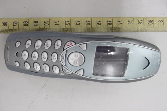
Click to zoom
Application Details
- Equipment Class
- DSS - Part 15 Spread Spectrum Transmitter
- Date of Grant
- May 11, 2005
- Application Purpose
- Original Equipment
- Date of Application
- May 11, 2005
- Equipment Note
- 2.4GHz WDCT Color Display
- Frequency Range
- 2401.05600000 - 2480.54400000
- Country
- Hong Kong
Documents & Files
Document Text
Text extracted from the exhibit documents filed with the FCC. Open a document above to read the original.
Users Manual
WDCT Color Display Important Instructions & Information 3 R0 Important Instructions & Information This User Guide provides you with all the information you need to get the most from your phone. You must first set up your phone before you can use it. This doesn’t take long and is easy to do. Just follow the simple instructions on the next few pages. Need help? If you have any problems setting up or using your Suncorp WDCT Color Display WDCT45-A2 telephone, contact the Help line at 86-755-2573-3333. Alternatively, you may find the answer in ‘ Troubleshooting Tips’ at the back of this guide. Did you receive everything? • WDCT45-A2 base • WDCT45-A2 handset • 2 x NiMH AAA rechargeable batteries • Battery compartment cover • AC power adaptor • Telephone line cord • Belt Clip In addition: If you have purchased one or more additional handsets (T1261), you will have received the following for each additional handset: • T1261 handset • T1261 charger • 2 x NiMH AAA Rechargeable batteries • Battery compartment cover • AC power adaptor • Belt Clip 4 Important Instructions & Information R0 Important Safety Instructions To reduce the risk of fire. Electric shock, and injury to persons when using your telephone equipment, basic safety precautions should always be followed which includes the following: 1. Read and understand all instructions. 2. Follow all warnings and instructions marked on the product 3. Unplug the equipment from the wall outlet before cleaning. Do not use liquid cleaners or aerosol cleaners. Use a damp cloth for cleaning. 4. Do not use this product near water, for example, near a bathtub, wash bowl, kitchen sink, or laundry tub, in a wet basement or near a swimming pool. 5. Do not place this product on an unstable cart, stand, or table. The product may fall, causing serious damage to the product. 6. This product should be operated only from the power source indicated on the marking label. If you are not sure of the type of power supply to your home, consult your dealer or local power company. 7. Do not allow anything to rest on the power cord. Do not locate this product where the cord will be abused by persons walking on it. 8. Do not overload wall outlets and extension cords as this can result in the risk of fire or electric shock. 9. Slots and openings in the cabinet at the back or bottom are provided for ventilation to protect it from overheating. These openings should never be blocked or covered. The openings should never be blocked by placing the product on the bed, sofa, rug, or other similar surface. This product should never be placed near or over a radiator or heat register. This product should not be placed in a built-in installation unless proper ventilation is provided. 10. Never push objects of any kind into this product through cabinets slots as they may touch dangerous voltage points or short out parts that could result in a risk of fire or electric shock. Never spill liquid of any kind on the product. 11. Do not use the telephone to report a gas leak in the vicinity of the leak. 12. Avoid using a telephone (other than a cordless type) during an electrical storm. There may be a remote risk of electric shock from lightning. 13. To reduce the risk of electric shock, do not disassemble this product, but take it to a qualified service contractor when some service or repair work is required. Opening or removing covers may expose you to dangerous voltage or other risks. Incorrect reassembly can cause electric shock when the unit is subsequently used. 14. Unplug the product from the wall outlet and refer to servicing to qualified personnel under the following conditions: A. If Liquid has been spilled into the product. B. When the power supply cord or plug is damaged or frayed. C. If the product does not operate normally by following the instruction manual. D. If the product has been dropped or the cabinet has been damaged. E. If the product exhibits a distinctive change in performance. Important Instructions & Information 5 R0 Battery Safety Instruction CAUTION: To reduce the risk of fire or personal injury, read and follow these instructions: 1. Use only the following type and size handset batteries: DC 1.2V, 750 mAh, Ni-MH (Nickel Metal Hydride), AAA size batteries (2 each). 2. When inserting the batteries into the product, the proper polarity or direction must be observed. Reverse insertion of the batteries can cause charging that may result in leakage or explosion. 3. Do not dispose of the batteries in a fire. The cell may explode. Check with local codes for possible special disposal instructions. 4. Do not open or mutilate the batteries. Released electrolyte is corrosive and may cause damage to the eyes and skin. It may be toxic if swallowed. 5. Exercise care in handling the battery in order not to short the battery with conduction material such as rings, bracelets and keys. The battery or conductor may overheat and cause burns. 6. Recharge only the batteries provided with or identified for use with this product. The battery may leak corrosive electrolyte or explode if it is not the correct type. 7. Do not attempt to rejuvenate the battery provided with or identified for use with this product by heating them. Sudden released of the electrolyte may occur causing damage to the eyes or skin. 8. Remove the batteries form the product if the product will not be used for a long period of time (over 30 days) since during this time the batteries may leak in the product. 9. Discard dead batteries as soon as possible since dead batteries are more likely to leak in the product. 10. Do not store this product, or the batteries provide, in high temperature areas. Batteries that are stored in a freezer or refrigerator for the purpose of extending shelf life should be stabilized at room temperature prior to use. 11. Disconnect telephone lines before installing batteries. 12. When replacing batteries, all batteries should be replaced at the same time. Mixing fresh and discharged batteries …
Text truncated - open the document above for the full version.
Users Manual
26 WDCT45-A2 Phonebook R0 If you subscribe to the Caller- ID service, and want the names in your Phonebook displayed instead of the phone number and name received by Caller-ID, you must store the telephone number exactly as received by Caller-ID (i.e., including the area code if received by Caller-ID). Writing tips Entering names Use the keypad letters to enter names. For example, to store TOM: 1. Press once to enter T. 2. Press three times to enter O. 3. Press once to enter M. If you make a mistake, press Clear to delete the last character or digit. Press to switch between upper and lower case letters. The icon will be displayed when you have selected upper case. Phonebook Full If the phonebook becomes full when adding entries, the screen shows Memory Full and then returns to standby. Phonebook Your Own Phonebook Directory Each WDCT45-A2 handset can store up to 150 names and numbers. Names can be up to 16 characters long and numbers up to 20 digits. Add Entry Manually 1. Press Names. 2. If the Phonebook is empty, Add Entry is highlighted. Press OK. 3. Or, if names have been stored, they are listed. Press Options. Add Entry is highlighted. Press OK. 4. Use the keypad to enter the name, then press OK. 5. Use the keypad to enter the number, then press OK. The screen shows the Names list. 6. Press and hold Back to return to standby. Add Entry from a Call List When reviewing a Call List (Received, Missed or Dialed) a call entry can be automatically copied into the Phonebook. 1. With Call entry highlighted, Press Options. 2. scroll to the highlight Save Number then press OK. 3. Name then Number information can be modified by using the Clear button, or if no change is desired, press OK, OK to save information without changes. A confirmation display and beep will be provided when the entry is saved. Using The WDCT45-A2 25 R0 Transfer a Call You can transfer a caller (for a regular telephone call) to another handset. During the call: 1. Press . Your caller is put on hold. 2. Enter the handset number you want to transfer the call to (1-4). 3. When the other handset answers you can tell them they have a call, then press . The call is then transferred. If the other handset does not answer or you decide not to transfer the call, press to talk to your caller. Caller on Hold You can put a call on hold, talk to another handset user, then resume your call. 1. During a call, press your caller is put on hold. 2. Enter the handset number you want to intercom call (1-4). 3. Press to end the intercom call and return to your regular call. The other handset presses Talk Off to end the call. 28 Suncorp Calling Features R0 CALLER-ID Information Sometimes the number and / or name information is not sent by the network. In this case you will see: • BLOCKED CALL When the caller has chosen to not send (block) their caller information. • BLOCKED NUMBER or NAME When only the number or name has been blocked. • UNKNOWN CALLER When caller information is not available in the network. • UNKNOWN NUMBER or NAME When only the number or name is not available. • INCOMPLETE DATA When no valid Caller-ID data was received. Make sure you have subscribed to the Caller-ID service. IMPORTANT The Caller-ID information is sent on the telephone line after the first ring signal. To ensure your Caller-ID information is received you should wait until after the start of the second ring to answer incoming calls. Call Features Managing Your Calls. You may subscribe to any of the following Suncorp services for which your WDCT45-A2 telephone has been designed to make these services easy to use. • Caller-ID • Caller-ID With Call Waiting • Call Waiting Deluxe • Voicemail • 3-Way Calling Fast access to Suncorp Optional Calling Feature services which may be available: • Directory Assistance • Call Return • Repeat Dialing • Call Forwarding • Voice Mail Access # & Indicator Caller-ID If you subscribe to the Caller-ID service, after the first ring you will see the number and name of who is calling you on your handset display, as well as the time and date of their call. Suncorp Calling Features 29 R0 Caller-ID With Call Waiting The Suncorp Call Waiting service provides you with a special tone when a caller is trying to call you while you are already on a call. The Caller-ID With Call Waiting (CIDCW) service blends the best of Call Waiting and Caller-ID services by showing you who is calling while you are already on a call. This service can be very useful to allow you to use your telephone without worrying about missing an important call. Because the caller's number and name are displayed, you can decide whether to put your current call on hold and answer the new waiting call, or ignore the new waiting call and continue talking on the current call. When you have subscribed to CIDCW and a new call is received while you are already on a call, you will here a special alerting signal and then the caller's information will be displayed. IMPORTANT To use the Suncorp calling features you will first need to subscribe to the desired features for which there may be a monthly charge from Suncorp Caller Information Display When using Call Waiting the WDCT45-A2 will show you the caller information of the caller you are connected to when you toggle between the first and second caller. If a Caller Hangs Up If you have an original call and a 2 nd call from Call Waiting active and one of these callers hangs up, you may hear a dialtone if you use the to connect to one of the callers. In this case you are ready to dial a 3-Way call. Press again to be connected to the remaining caller. If one of the callers hangs- up, the WDCT45-A2 may not recognize this and may display the incorrect caller information on the display. 30 Suncorp Calling Features R0 If You Forget a Waiting Call It is possible you may have a call on hold (waiting) and finish your conversation with one caller and hang up. In this case, the phone should ring again with the call from the waiting caller. CALL WAI…
Text truncated - open the document above for the full version.
Cover Letter(s)
1 Subject:FW: Suncorp Communications Limited, FCC ID: S9AWDCT45-A2, Assessment NO.: AN05T4772, Notice#1 Exhibit-C-Test_Rep ort-1.pdf Exhibit-C-Test_Rep ort-2.pdf Exhibit-D-ID_Label. pdf Exhibit-E-User_Man ual_revised.... From: SS Sent: Thursday, May 12, 2005 3:29 AM Subject: Re: Suncorp Communications Limited, FCC ID: S9AWDCT45-A2, Assessment NO.: AN05T4772, Notice#1 #1 There are 92 channels. Please refer to test report. #2 The test report was revised. #3 The test plots was provided and revised. #4 The test plots was provided and revised. #5 The test report was revised. #6 The test report was revised. #7 The test plots was revised. #8 The test report was revised. #9 The test report was revised. #10 The test plots was revised. #11 The test report was revised. #12 Please find attached E-Probe document. #13 Please find attached FCC ID label. #14 Please find revised user manual. EMC Test report Question #1: Please verify the number of channels used in this device. There is no RF module chipset datasheet provided in the filing. The simple Operational Description does not explain clearly. In EMC test report, section 1.2 as well as operational description says 92 channels; section 4.4.2 mentioned channel 00 and 90, which means 91 channels totally; section 8 says the number of channel measured is 90, while all the other sections mentioned channel 00, 46, 92, which means 93 channels. Please provide a list of frequency vs. channel number and modify the test report accordingly. Please make sure the low, middle and high channel in the report refer to the relevant frequencies consistently in the report. Question #2: Section 5.3 Conducted emission: it says Headset unit link, which does not agree with the setup photos. Actually it should be Base Unit link. Please correct. Question #3: Section 10 Dwell time: Please explain why you use •• 36x1.3x0.86ms40.248 ms to calculate dwell time for base unit, while you •• use 36x3.6x0.86ms111.456 ms to calculate dwell time for headset unit. 2 What does 1.3 and 3.6 come from? Question #4: Appendix 3 plots of number of hopping frequency: both span and RBW setting might be too big, the plots are not clear enough to show the result. Please try smaller RBW or span. Question #5: Appendix 6 Plots of power output: sheet 33 of 54 does not indicate the frequency and span, please add a note to specify. Question #6: Appendix 7 Plots of 100k bandwidth of bandedge: there is pdf reading error found in sheet 40-43: no content displayed. Please reconvert the report. Question #7: Appendix 8 Plots of out-of-band conducted emission: please explain what is "uncal" on plots of sheet 49 and 50. SAR Test Report: Question #8: Page 3, Date of test - There is discrepancy between date of test and actual date of test (please refer to page 15-16 and test plots). Question #9: Page 4 indicates that max. output power/average is 23.4dBm, which is even higher than the peak power output in EMC test report (23.17dBm). The power deviation between SAR testing and EMC testing, allowed by FCC, must be within 0.5dBm. Please provide average power in EMC report for reference. Question #10: The user manual indicates clearly that belt clip will be provided to the user as accessory. However body-worn position was not investigated. Please provide SAR data for body worn test position. Question #11: Page 23, Test equipment list - Some of test equipment are out of cal. i.e Signal Generator (Agilent, 83630B), DAE (SPEAG, 427) and E-filed Probe (ET3DV6). please update. Question #12: Please provide certificate of E-Field Probe (EX3DV4 - SN 3554). FCC ID label format Question #13: FCC ID label format is missing in the filing. Please make sure cordless phone warning statement as specified in FCC15.214 is included. User manual: Question #14: Please remove 20cm distance limitation from the manual. As the headset is considered as a portable device and SAR testing is performed. But 3 you may need to add similar statement as "For body worn operation, this phone has been tested and meets FCC RF exposure guidelines when used with an accessory that contains no metal and that positions the handset a minimum of xxcm from the body. Use of other accessories may not ensure compliance with FCC RF exposure guidelines." xx: the thickness of the belt-clip.
External Photos
ETC Report No. : ET94R-03-140 FCC ID. : S9AWDCT45-A2 Rev. No 1.0 CONSTRUCTED PHOTOS of EUT A. Base Unit Front View of Base Unit Rear View of Base Unit ETC Report No. : ET94R-03-140 FCC ID. : S9AWDCT45-A2 Rev. No 1.0 CONSTRUCTED PHOTOS of EUT Side View of Base Unit Side View of Base Unit ETC Report No. : ET94R-03-140 FCC ID. : S9AWDCT45-A2 Rev. No 1.0 CONSTRUCTED PHOTOS of EUT B. Handset Front View of Handset Rear View of Handset ETC Report No. : ET94R-03-140 FCC ID. : S9AWDCT45-A2 Rev. No 1.0 CONSTRUCTED PHOTOS of EUT Side View of Handset Side View of Handset ETC Report No. : ET94R-03-140 FCC ID. : S9AWDCT45-A2 Rev. No 1.0 CONSTRUCTED PHOTOS of EUT C. Adaptor Front View of Adaptor Rear View of Adaptor ETC Report No. : ET94R-03-140 FCC ID. : S9AWDCT45-A2 Rev. No 1.0 CONSTRUCTED PHOTOS of EUT D. Charger Front View of Charger Rear View of Charger ETC Report No. : ET94R-03-140 FCC ID. : S9AWDCT45-A2 Rev. No 1.0 CONSTRUCTED PHOTOS of EUT Side View of Charger Side View of Charger
Internal Photos
ETC Report No. : ET94R-03-140 FCC ID. : S9AWDCT45-A2 Rev. No 1.0 CONSTRUCTED PHOTOS of EUT Internal View of Base Unit Component View of Base Unit’s Main PCB ETC Report No. : ET94R-03-140 FCC ID. : S9AWDCT45-A2 Rev. No 1.0 CONSTRUCTED PHOTOS of EUT Component View of Base Unit’s Main PCB Solder View of Base Unit’s Main PCB ETC Report No. : ET94R-03-140 FCC ID. : S9AWDCT45-A2 Rev. No 1.0 CONSTRUCTED PHOTOS of EUT Internal View of Handset ETC Report No. : ET94R-03-140 FCC ID. : S9AWDCT45-A2 Rev. No 1.0 CONSTRUCTED PHOTOS of EUT Component View of Handset’s Main PCB Solder View of Handset‘s Main PCB ETC Report No. : ET94R-03-140 FCC ID. : S9AWDCT45-A2 Rev. No 1.0 CONSTRUCTED PHOTOS of EUT Solder View of Handset‘s Main PCB ETC Report No. : ET94R-03-140 FCC ID. : S9AWDCT45-A2 Rev. No 1.0 CONSTRUCTED PHOTOS of EUT Internal View of Adaptor ETC Report No. : ET94R-03-140 FCC ID. : S9AWDCT45-A2 Rev. No 1.0 CONSTRUCTED PHOTOS of EUT Component View of Adaptor‘s Main PCB Solder View of Adaptor‘s Main PCB ETC Report No. : ET94R-03-140 FCC ID. : S9AWDCT45-A2 Rev. No 1.0 CONSTRUCTED PHOTOS of EUT Internal View of Charger ETC Report No. : ET94R-03-140 FCC ID. : S9AWDCT45-A2 Rev. No 1.0 CONSTRUCTED PHOTOS of EUT Component View of Charger‘s Main PCB Solder View of Charger‘s Main PCB
RF Exposure Info
Compliance Certification Services Inc. Report No: 50503104-SF FCC ID: S9AWDCT45-A2 Date of Issue: May 12, 2005 Note: This report shall not be reproduced except in full, without the written approval of Compliance Certification Services Inc. This document may be altered or revised by Compliance Certification Services Inc. personnel only, and shall be noted in the revision section of the document. Page 1 Total Page: 27 Rev. 00 ANSI/IEEE Std. C95.1-1992 in accordance with the requirements of FCC Report and Order: ET Docket 93-62, and OET Bulletin 65 Supplement C FCC TEST REPORT For 2.4GHz WDCT Color Display Trade Name: N/A Model: WDCT45-A2 Issued to SunCorp Communications Limited Room 1907-08, Harcourt House, 39 Gloucester Road, Wanchai, Hong Kong Issued by Compliance Certification Services Inc. No. 11, Wu-Kung 6 Rd, Wu-Ku Hsiang, Wu-Ku Industrial District, Taipei Hsien, (248) Taiwan. TEL: 886-2-2299-9720 FAX: 886-2-2299-9721 Compliance Certification Services Inc. Report No: 50503104-SF Date of Issue: May 12, 2005 Page 2 Rev. 00 TABLE OF CONTENTS 1. EUT DESCRIPTION ....................................................................................................................4 2. REQUIREMENTS FOR COMPLIANCE TESTING DEFINED BY THE FCC .........................5 3. DOSIMETRIC ASSESSMENT SYSTEM ...................................................................................5 3.1 MEASUREMENT SYSTEM DIAGRAM....................................................................................6 3.2 SYSTEM COMPONENTS ...........................................................................................................7 4. EVALUATION PROCEDURES ..................................................................................................9 5. MEASUREMENT UNCERTAINTY .........................................................................................13 6. EXPOSURE LIMIT ....................................................................................................................14 7. TYPICAL COMPOSITION OF INGREDIENTS FOR LIQUID TISSUE PHANTOMS .........14 8. MEASUREMENT RESULTS ....................................................................................................15 8.1 SYSTEM PERFORMANCE CHECK................................................................................................ 15 8.2 TEST LIQUID CONFIRMATION...................................................................................................... 16 8.3 EUT TUNE-UP PROCEDURES......................................................................................................... 17 8.4 SAR MEASUREMENTS RESULTS.................................................................................................. 19 9. EUT PHOTOS............................................................................................................................24 10. EQUIPMENT LIST & CALIBRATION STATUS....................................................................25 11. FACILITIES ...............................................................................................................................26 12. REFERENCES............................................................................................................................26 13. ATTACHMENTS .......................................................................................................................27 Compliance Certification Services Inc. Report No: 50503104-SF Date of Issue: May 12, 2005 Page 3 Rev. 00 CERTIFICATE OF COMPLIANCE (SAR EVALUATION) Applicant: SunCorp Communications Limited Room 1907-08, Harcourt House, 39 Gloucester Road, Wanchai, Hong Kong Equipment Under Test: 2.4GHz WDCT Color Display Trade Name: N/A Model Number: WDCT45-A2 Date of Test: April 29, and May 04, 2005 Device Category: PORTABLE DEVICES Exposure Category: GENERAL POPULATION/UNCONTROLLED EXPOSURE APPLICABLE STANDARDS STANDARD TEST RESULT FCC OET 65 Supplement C No non-compliance noted Deviation from Applicable Standard None The device was tested by Compliance Certification Services Inc. in accordance with the measurement methods and procedures specified in OET Bulletin 65 Supplement C (Edition 01-01). The test results in this report apply only to the tested sample of the stated device/equipment. Other similar device/equipment will not necessarily produce the same results due to production tolerance and measurement uncertainties. Approved by: Reviewed by: Harris W. Lai Chris Hsieh Executive Vice President Section Manager Compliance Certification Services Inc. Compliance Certification Services Inc. Compliance Certification Services Inc. Report No: 50503104-SF Date of Issue: May 12, 2005 Page 4 Rev. 00 1. EUT DESCRIPTION Product 2.4GHz WDCT Color Display Trade Name N/A Model Number WDCT45-A2 Model Discrepancy N/A Frequency Range 2402 ~ 2480 MHz Max. O/P Power: (Conducted/Average) Head: 23.24dBm Body: 23.22dBm Max. SAR (1g): Head: 0.0379 W/kg Body: 0.0340 W/kg Modulation Technique FHSS (GFSK) Antenna Specification Antenna type: Monopole antenna Battery option: Only one type / model with EUT Test Host: COMPAQ; P/N: P1500; S/N: 1V31LDLZ3407 Remark: The sample selected for test was prototype that approximated to production product and was provided by manufacturer. Compliance Certification Services Inc. Report No: 50503104-SF Date of Issue: May 12, 2005 Page 5 Rev. 00 2. REQUIREMENTS FOR COMPLIANCE TESTING DEFINED BY THE FCC The US Federal Communications Commission has released the report and order “Guidelines for Evaluating the Environmental Effects of RF Radiation", ET Docket No. 93-62 in August 1996 [1]. The order requires routine SAR evaluation prior to equipment authorization of portable transmitter devices, including portable telephones. For consumer products, the applicable limit is 1.6 mW/g for an uncontrolled environment and 8.0 mW/g for an occupational/controlled environment as recommended by the ANSI/IEEE standard C95.1-1992 [6]. According t…
Text truncated - open the document above for the full version.
RF Exposure Info
Date/Time: 4/29/2005 11:23:07 AM Test Laboratory: Compliance Certification Services Inc. D2450V2-SN 728-Head DUT: Dipole 2450 MHz; Type: D2450V2; Serial: D2450V2 - SN:728 Communication System: CW2450; Frequency: 2450 MHz;Duty Cycle: 1:1 Medium parameters used: f = 2450 MHz; σ = 1.84 mho/m; ε r = 37.5; ρ = 1000 kg/m 3 Air Temperature:24.8 deg C;Liquid Temperature:23.6 deg C Area scan setting: Find secondary maxima within 2 dB, and with a peak SAR value greater than 0.0012 mW/g Zoom scan setting: Maximum number of cubes to measure is 2 Phantom section: Flat Section DASY4 Configuration: z Probe: EX3DV4 - SN3554; ConvF(6.2, 6.2, 6.2); Calibrated: 11/19/2004 z Sensor-Surface: 4mm (Mechanical Surface Detection)Sensor-Surface: 0mm (Fix Surface) z Electronics: DAE3 Sn558; Calibrated: 8/24/2004 z Phantom: SAM 34; Type: SAM V4.0; Serial: TP-1150 z Measurement SW: DASY4, V4.5 Build 19; Postprocessing SW: SEMCAD, V1.8 Build 146 Pin=250mW,d=10mm/Area Scan (6x6x1): Measurement grid: dx=15mm, dy=15mm Maximum value of SAR (measured) = 8.92 mW/g Pin=250mW,d=10mm/Z Scan (1x1x21): Measurement grid: dx=20mm, dy=20mm, dz=5mm Maximum value of SAR (measured) = 20.7 mW/g Pin=250mW,d=10mm/Zoom Scan (5x5x7)/Cube 0: Measurement grid: dx=7.5mm, dy=7.5mm, dz=5mm Reference Value = 89.1 V/m; Power Drift = 0.123 dB Peak SAR (extrapolated) = 29.1 W/kg SAR(1 g) = 14.0 mW/g; SAR(10 g) = 5.91 mW/g Maximum value of SAR (measured) = 14.3 mW/g Page1 Page2 Date/Time: 5/4/2005 10:35:31 AM Test Laboratory: Compliance Certification Services Inc. D2450V2-SN 728-Body DUT: Dipole 2450 MHz; Type: D2450V2; Serial: D2450V2 - SN:728 Communication System: CW2450; Frequency: 2450 MHz;Duty Cycle: 1:1 Medium parameters used: f = 2450 MHz; σ = 1.91 mho/m; ε r = 51.1; ρ = 1000 kg/m 3 Air Temperature:25.5 deg C;Liquid Temperature:24.3 deg C Area scan setting: Find secondary maxima within 2 dB, and with a peak SAR value greater than 0.0012 mW/g Zoom scan setting: Maximum number of cubes to measure is 2 Phantom section: Flat Section DASY4 Configuration: z Probe: EX3DV4 - SN3554; ConvF(6.14, 6.14, 6.14); Calibrated: 11/19/2004 z Sensor-Surface: 4mm (Mechanical Surface Detection)Sensor-Surface: 0mm (Fix Surface) z Electronics: DAE3 Sn558; Calibrated: 8/24/2004 z Phantom: SAM 34; Type: SAM V4.0; Serial: TP-1150 z Measurement SW: DASY4, V4.5 Build 19; Postprocessing SW: SEMCAD, V1.8 Build 146 Pin=250mW,d=10mm/Area Scan (6x6x1): Measurement grid: dx=15mm, dy=15mm Maximum value of SAR (measured) = 9.37 mW/g Pin=250mW,d=10mm/Z Scan (1x1x21): Measurement grid: dx=20mm, dy=20mm, dz=5mm Maximum value of SAR (measured) = 21.2 mW/g Pin=250mW,d=10mm/Zoom Scan (5x5x7)/Cube 0: Measurement grid: dx=7.5mm, dy=7.5mm, dz=5mm Reference Value = 87.8 V/m; Power Drift = 0.079 dB Peak SAR (extrapolated) = 30.0 W/kg SAR(1 g) = 13.1 mW/g; SAR(10 g) = 5.74 mW/g Maximum value of SAR (measured) = 14.9 mW/g Page1 Page2 Date/Time: 4/29/2005 12:43:15 PM Test Laboratory: Compliance Certification Services Inc. Left Head Page1 Date/Time: 4/29/2005 5:32:31 PM Test Laboratory: Compliance Certification Services Inc. 2.4G Left Head DUT: WDCT45-A2; Type: 2.4GHz WDCT Color Display; Serial: N/A Communication System: 2.4G ; Frequency: 2402 MHz;Duty Cycle: 1:11.9 Medium parameters used: f = 2402 MHz; σ = 1.84 mho/m; ε r = 37.5; ρ = 1000 kg/m 3 Air Temperature:24.8 deg C;Liquid Temperature:23.6 deg C Area scan setting: Find secondary maxima within 2 dB, and with a peak SAR value greater than 0.0012 mW/g Zoom scan setting: Maximum number of cubes to measure is 2 Phantom section: Left Section DASY4 Configuration: z Probe: EX3DV4 - SN3554; ConvF(6.2, 6.2, 6.2); Calibrated: 11/19/2004 z Sensor-Surface: 4mm (Mechanical Surface Detection) z Electronics: DAE3 Sn558; Calibrated: 8/24/2004 z Phantom: SAM 12; Type: SAM V4.0; Serial: TP-1150 z Measurement SW: DASY4, V4.5 Build 19; Postprocessing SW: SEMCAD, V1.8 Build 146 Left Cheek Low CH01/Area Scan (6x13x1): Measurement grid: dx=15mm, dy=15mm Maximum value of SAR (measured) = 0.026 mW/g Left Cheek Low CH01/Zoom Scan (5x5x7)/Cube 0: Measurement grid: dx=7.5mm, dy=7.5mm, dz=5mm Reference Value = 3.78 V/m; Power Drift = -0.149 dB Peak SAR (extrapolated) = 0.037 W/kg SAR(1 g) = 0.0242 mW/g; SAR(10 g) = 0.012 mW/g Maximum value of SAR (measured) = 0.028 mW/g Page1 Date/Time: 4/29/2005 11:57:18 AM Test Laboratory: Compliance Certification Services Inc. 2.4G Left Head DUT: WDCT45-A2; Type: 2.4GHz WDCT Color Display; Serial: N/A Communication System: 2.4G ; Frequency: 2441 MHz;Duty Cycle: 1:11.9 Medium parameters used: f = 2441 MHz; σ = 1.84 mho/m; ε r = 37.5; ρ = 1000 kg/m 3 Air Temperature:24.8 deg C;Liquid Temperature:23.6 deg C Area scan setting: Find secondary maxima within 2 dB, and with a peak SAR value greater than 0.0012 mW/g Zoom scan setting: Maximum number of cubes to measure is 2 Phantom section: Left Section DASY4 Configuration: z Probe: EX3DV4 - SN3554; ConvF(6.2, 6.2, 6.2); Calibrated: 11/19/2004 z Sensor-Surface: 4mm (Mechanical Surface Detection) z Electronics: DAE3 Sn558; Calibrated: 8/24/2004 z Phantom: SAM 12; Type: SAM V4.0; Serial: TP-1150 z Measurement SW: DASY4, V4.5 Build 19; Postprocessing SW: SEMCAD, V1.8 Build 146 Left Cheek Middle CH46/Area Scan (6x13x1): Measurement grid: dx=15mm, dy=15mm Maximum value of SAR (measured) = 0.033 mW/g Left Cheek Middle CH46/Zoom Scan (5x5x7)/Cube 0: Measurement grid: dx=7.5mm, dy=7.5mm, dz=5mm Reference Value = 4.31 V/m; Power Drift = 0.065 dB Peak…
Text truncated - open the document above for the full version.
Contact Information
Applicant
CW Cheung(Head of Engineering Department)
Test Firm
Electronics Testing Center, TaiwanWill Yauo
Technical Specifications
| # | Rule Parts | Frequency Range | Power Output |
|---|---|---|---|
| 1 | 15C | 2.40 GHz - 2.48 GHz | 207.49 mW |
Other Applications from SunCorp Communications Limited

S9ADECT33-B70-B31
Mar 22, 2007US DECT PHONE--BASE
Equipment Class
JBP - Part 15 Class B Computing Device Peripheral
S9ADECT34-S37TAM
Feb 05, 2007Digital Cordless Phone - Base Unit
Equipment Class
PUB - Part 15 Unlicensed PCS Base Station
S9ADECT33-B64-B68
Jan 16, 2007US DECT PHONE- HEADSET
Equipment Class
PUE - Part 15 Unlicensed PCS portable Tx held to ear
S9ADECT33-B18-B32
Jan 14, 2007US DECT PHONE - HEADSET
Equipment Class
PUE - Part 15 Unlicensed PCS portable Tx held to ear
S9ADECT64-S96-B11
Jan 14, 2007US DECT PHONE- BASE
Equipment Class
PUB - Part 15 Unlicensed PCS Base Station