SAN-PP400BGXPePLink PolePoint Outdoor 400BG
PePLink Ltd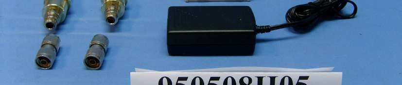
Click to zoom
Application Details
- Equipment Class
- DTS - Digital Transmission System
- Date of Grant
- Jun 05, 2006
- Application Purpose
- Original Equipment
- Date of Application
- Jun 05, 2006
- Equipment Note
- PePLink PolePoint Outdoor 400BG
- Frequency Range
- 2412.00000000 - 2462.00000000
- Company
- PePLink Ltd
- Country
- Hong Kong
Documents & Files
Document Text
Text extracted from the exhibit documents filed with the FCC. Open a document above to read the original.
Users Manual
PePLink PolePoint 200BG / 400 BG User Manual Document Revision : 1.2 Firmware Version : 2.2 Date : 2006-05-02 PePLink PolePoint 200BG / 400BG User Manual Copyright © 1999-2006 PePLink Ltd. All Rights Reserved Page 2 of 20 Table of Content 1 Introduction ....................................................................................................................................................... 3 2 Feature Highlights ............................................................................................................................................. 3 3 Product Package ................................................................................................................................................ 3 4 Installation.......................................................................................................................................................... 4 4.1 Procedures .................................................................................................................................................... 5 4.2 Quick Start .................................................................................................................................................... 6 5 Configurations ................................................................................................................................................... 7 5.1 WLANs Settings ........................................................................................................................................... 7 5.2 SNMP Settings............................................................................................................................................ 11 5.3 Web Admin Settings ................................................................................................................................... 14 5.4 Message Log............................................................................................................................................... 15 5.5 Commands .................................................................................................................................................. 16 6 Per-session based VLAN tagging.................................................................................................................... 17 7 Appendix A - FAQ............................................................................................................................................ 18 8 Appendix B – Radius Server Setup ................................................................................................................ 19 9 Appendix C - Professional Installation..................................................................................20 PePLink PolePoint 200BG / 400BG User Manual Copyright © 1999-2006 PePLink Ltd. All Rights Reserved Page 3 of 20 1 Introduction PePLink PolePoint is a carrier-grade 802.11b/g Wi-Fi access point. It is a powerful solution for building wholesale wireless networks. Each PePLink PolePoint is loaded with essential features such as Multiple SSID (virtual AP with distinct ESSID and BSSID), VLAN and a high-power antenna One PePLink PolePoint can masquerade up to 16 different access points. Each virtual access point can have its own security policy (WEP, WPA, WPA2, 802.1x) and authentication mechanism. All these mean you can build your wholesale network much faster, easier and more cost-effective than ever before. PePLink PolePoint comes equipped with a high-power Wi-Fi transmitter (26 dBm for PolePoint 400BG, 23 dBm for PolePoint 200BG) which greatly enhances coverage and performance. 2 Feature Highlights • Designed for wholesale wireless networks with multiple SSID and VLAN support • Independent security policy and encryption mechanism per virtual AP. • Hardware Watchdog increases service availability and guarantees firmware integrity ownership • High-power output (up to 26 dBm) enhances coverage and lowers cost of ownership 3 Product Package The following items are included in the PePLink PolePoint package: 1 x PePLink PolePoint 1 x Reverse-Polarity TNC Antenna 1 x Power Adapter (output: DC 5V) 1 x User’s Manual (this manual) PePLink PolePoint 200BG / 400BG User Manual Copyright © 1999-2006 PePLink Ltd. All Rights Reserved Page 4 of 20 4 Installation The PePLink PolePoint is acted as an Ethernet Bridge between the wireless and the Ethernet interface. The network setup is typically like this: Backbone network WISP 3 WISP 2 WISP 1 Switch VLAN Tagged Radius Server Pow erStatusLAN Wi-Fi PePLink PolePoint Figure 1 PePLink PolePoint 200BG / 400BG User Manual Copyright © 1999-2006 PePLink Ltd. All Rights Reserved Page 5 of 20 4.1 Procedures • Attach the antenna to the PePLink PolePoint unit. • Connect its LAN port with the backbone network using either a straight-through or cross-over cable. • Plug the power adapter to a power socket and also the power input jack on the unit. • Wait until the status LED turns green • Connect a PC to the backbone network, configure its IP address to be any IP address between 192.168.0.4 to 192.168.0.254 with subnet mask of 255.255.255.0 • Visit the URL https://192.168.0.3/ (note that it is “HTTPS” based) using Microsoft Internet Explorer 5 or above, or Mozilla Firefox 1.0 or above. Accept all prompted questions • You will be prompted for admin login ID and password. By default, they are “admin” and “public”. • You will see a page like this: • You may now start to configure the PePLink PolePoint Figure 2 Tips: If you are unable to access the page, please refer to the Appendix A - FAQ for how to restore the settings to factory defaults. PePLink PolePoint 200BG / 400BG User Manual Copyright © 1999-2006 PePLink Ltd. All Rights Reserved Page 6 of 20 4.2 Quick Start With the default settings, an SSID is predefined, which is “PePLink_XXXX” where XXXX is the last 4 digits of the MAC Address. It has both encryption and VLAN tagg…
Text truncated - open the document above for the full version.
Cover Letter(s)
From: [email protected] [mailto:[email protected]] Sent: Thursday, June 01, 2006 10:42 PM To: steve.cheng Cc: [email protected]; [email protected]; [email protected] Subject: Re : TCB Review Comments for (B06-0529a- SAN-PP400BGX- PePLinkPolePointOutdoor) Dear Steve, Please see our reply below. Thanks! Best Regards, Amanda Chu / 朱芳誼 Certification Specialist / ADT Corp. (Hsin Chu Office) Tel: 03-5935343 ext. 1737 Fax: 03-5934728 "steve.cheng" <[email protected]> 2006/05/30 下午 04:06 收件 人 [email protected] 副本 抄送 [email protected], [email protected], [email protected] 主旨 TCB Review Comments for (B06-0529a- SAN-PP400BGX- PePLink PolePointOutdoor) TCB Review Comments for (B06-0529a- SAN-PP400BGX- PePLink PolePoint Outdoor) -EMC- Question #1: If certified module is used for this product, then label needs to show “Contains FCC ID: xxxx” , otherwise please remove related info from test report and treat this as a new application and supply block diagram and schematic. <Reply>The 11bg module is purchased from OEM and this product already been certified as a module, but due to the use of different output power and antenna, we have retest whole radio. Due to confidential concern, the schematic and block diagram is not available from OEM. Please refer to original filing FCC ID: SWX-SR2. The product is identical, except different output power and antenna are incorporated in this application. Question #2: Product seems for professional installed product and standard N type connector is used in the product. However, no professional installation declaration letter and related info are found in the manual. Please clarify if this is a professional installed device. <Reply> Product is for professional installation only, please see uploaded declaration letter and revised manual. Best regards, Steve Cheng Email: [email protected]
External Photos
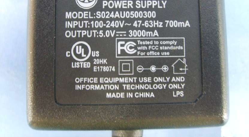
Page 1 CONSTRUCTION PHOTOS OF EUT
ID Label/Location Info
FCC LABEL LOCATION The label will be permanently affixed at a conspicuous location on the device. Label FCC ID: SAN-PP400BGX
Internal Photos
Page 2 Page 3 Page 4 Page 5 Page 6 Page 7 Page 8 Page 9 Page 10 Page 11 Page 12 Page 13 Page 14 Page 15 Page 16 Page 17 Page 18 Page 19 Page 20 Page 21 Page 22 Page 23 Page 24 Page 25 Page 26
Operational Description
FCC ID: SAN-PP400BGX Report No. RF950508H05 Operational Description This device is a PePLink PolePoint Outdoor 400BG, the maximum data rate could be up to 54Mbps which OFDM technique will be applied. If the signal to noise radio is too poor which could not support 54Mbps, the 11Mbps data rate with CCK technique will be applied. The transmitter of the EUT (PePLink PolePoint Outdoor 400BG) is powered by POE (Power over Ethernet). The antennas used in this product are as following: Antenna TypeGain (dBi)Connector Type Dipole Antenna8 dBiN type female The other instruction, please have a look at the users manual.
RF Exposure Info
Report No.: SA950508H05 1 RF EXPOSURE REPORT REPORT NO.: SA950508H05 MODEL NO.: PePLink PolePoint Outdoor 400BG FCC ID: SAN-PP400BGX ACCORDING: FCC Guidelines for Human Exposure IEEE C95.1 APPLICANT:PePLink Ltd. ADDRESS:2302, Tai Tung Building 8 Fleming Road, Wanchai, Hong Kong ISSUED BY:Advance Data Technology Corporation LAB LOCATION:No. 81-1, Lu Liao Keng, 9 Ling, Wu Lung Tsuen, Chiung Lin Hsiang, Hsin Chu Hsien, Taiwan, R.O.C. Report No.: SA950508H05 2 RF Exposure Measurement 1. Introduction In this document, we try to prove the safety of radiation harmfulness to the human body for our product. The limit for Maximum Permissible Exposure (MPE) specified in FCC 1.1310 is followed. The Gain of the antenna used in this product is measured in a Fully Anechoic Chamber (FAC) calibrated for antenna measurement in ADT, and also the maximum total power input to the antenna is measured. Through the Friis transmission formula and the maximum gain of the antenna, we can calculate the distance, away from the product, where the limit of MPE is reached. Although the Friis transmission formula is a far field assumption, the calculated result of that is an over-prediction for near field power density. We will take that as the worst case to specify the safety range. 2. RF Exposure Limit According to FCC 1.1310: The criteria listed in the following table shall be used to evaluate the environmental impact of human exposure to radio-frequency (RF) radiation as specified in 1.1307(b) LIMITS FOR MAXIMUM PERMISSIBLE EXPOSURE (MPE) Frequency Range (MHz) Electric Field Strength (V/m) Magnetic Field Strength (A/m) Power Density (mW/cm 2 ) Average Time (minutes) (A)Limits For Occupational / Control Exposures 300-1500......F/3006 1500-100,000......56 (B)Limits For General Population / Uncontrolled Exposure 300-1500......F/15006 1500-100,000......1.030 F = Frequency in MHz Report No.: SA950508H05 3 3. Friis Formula Friis transmission formula : Pd = (Pout*G) / (4*pi*r 2 ) where Pd = power density in mW/cm 2 Pout = output power to antenna in mW G = gain of antenna in linear scale Pi = 3.1416 R = distance between observation point and center of the radiator in cm Pd is the limit of MPE, 1 mW/cm 2 . If we know the maximum Gain of the antenna and the total power input to the antenna, through the calculation, we will know the MPE value at distance 20cm. Ref. : David K. Cheng, Field and Wave Electromagnetics, Second Edition, Page 640, Eq. (11-133). 4. EUT Operating condition The software provided by Manufacturer enabled the EUT to transmit and receive data at lowest, middle and highest channel individually. 5. Classification The antenna of this product, under normal use condition, is at least 20cm away from the body of the user. Warning statement to the user for keeping at least 20cm or more separation distance with the antenna should be included in users manual. So, this device is classified as Mobile Device Report No.: SA950508H05 4 6. Test Results 6.1 Antenna Gain The maximum Gain measured in Fully Anechoic Chamber is 8dBi or 6.309573(numeric) 6.2 Output Power Into Antenna & RF Exposure value at distance 20cm: For Part 802.11b: Channel Channel Frequency (MHz) Output Power to Antenna (mW) Power Density (mW/cm 2 ) Limit of Power Density (mW/cm 2 ) 1241285.1140.1071.0 62437151.3560.1901.0 11246289.1250.1121.0 For Part 802.11g: Channel Channel Frequency (MHz) Output Power to Antenna (mW) Power Density (mW/cm 2 ) Limit of Power Density (mW/cm 2 ) 12412257.0400.3231.0 62437398.1070.5001.0 112462213.7960.2681.0
Test Report
Report No.: RF950508H051Report Format Version 2.0.4 FCC TEST REPORT REPORT NO.:RF950508H05 MODEL NO.:PePLink PolePoint Outdoor 400BG RECEIVED:May 08, 2006 TESTED:May 03 to 19, 2006 ISSUED: May 23, 2006 APPLICANT:PePLink Ltd. ADDRESS:2302, Tai Tung Building 8 Fleming Road, Wanchai, Hong Kong ISSUED BY:Advance Data Technology Corporation LAB LOCATION:No. 81-1, Lu Liao Keng, 9 Ling, Wu Lung Tsuen, Chiung Lin Hsiang, Hsin Chu Hsien, Taiwan, R.O.C. This test report consists of 67 pages in total. It may be duplicated completely for legal use with the approval of the applicant. It should not be reproduced except in full, without the written approval of our laboratory. The client should not use it to claim product endorsement by CNLA, A2LA or any government agencies. The test results in the report only apply to the tested sample. The test results in this report are traceable to the national or international standards. No. 2177-01 Report No.: RF950508H052Report Format Version 2.0.4 Table of Contents 1CERTIFICATION ........................................................................................... 4 2SUMMARY OF TEST RESULTS................................................................... 5 3GENERAL INFORMATION ........................................................................... 6 3.1GENERAL DESCRIPTION OF EUT.............................................................. 6 3.2DESCRIPTION OF TEST MODES................................................................ 8 3.3TEST MODE APPLICABLITY AND TESTED CHANNEL DETAIL: ................ 9 3.4GENERAL DESCRIPTION OF APPLIED STANDARDS ..............................11 3.5DESCRIPTION OF SUPPORT UNITS........................................................ 12 3.6CONFIGURATION OF SYSTEM UNDER TEST ......................................... 13 4TEST TYPES AND RESULTS..................................................................... 14 4.1CONDUCTED EMISSION MEASUREMENT .............................................. 14 4.1.1LIMITS OF CONDUCTED EMISSION MEASUREMENT ........................... 14 4.1.2TEST INSTRUMENTS ................................................................................ 14 4.1.3TEST PROCEDURES................................................................................. 15 4.1.4TEST SETUP .............................................................................................. 15 4.1.5EUT OPERATING CONDITIONS................................................................ 16 4.1.6TEST RESULTS.......................................................................................... 17 4.2RADIATED EMISSION MEASUREMENT ................................................... 19 4.2.1LIMITS OF RADIATED EMISSION MEASUREMENT ................................ 19 4.2.2TEST INSTRUMENTS ................................................................................ 20 4.2.3TEST PROCEDURES................................................................................. 21 4.2.4TEST SETUP .............................................................................................. 22 4.2.5EUT OPERATING CONDITIONS................................................................ 22 4.2.6TEST RESULTS.......................................................................................... 23 4.2.7TEST RESULTS - DSSS............................................................................. 24 4.2.8TEST RESULTS - OFDM ............................................................................ 31 4.36dB BANDWIDTH MEASUREMENT .......................................................... 38 4.3.1LIMITS OF 6dB BANDWIDTH MEASUREMENT........................................ 38 4.3.2TEST INSTRUMENTS ................................................................................ 38 4.3.3TEST PROCEDURE ................................................................................... 39 4.3.4TEST SETUP .............................................................................................. 39 4.3.5EUT OPERATING CONDITIONS................................................................ 39 4.3.6TEST RESULTS –DSSS ............................................................................. 40 4.3.7TEST RESULTS-OFDM .............................................................................. 43 4.4MAXIMUM PEAK OUTPUT POWER .......................................................... 46 4.4.1LIMITS OF MAXIMUM PEAK OUTPUT POWER MEASUREMENT ........... 46 4.4.2TEST INSTRUMENTS ................................................................................ 46 4.4.3TEST PROCEDURES................................................................................. 47 4.4.4TEST SETUP .............................................................................................. 47 Report No.: RF950508H053Report Format Version 2.0.4 4.4.5EUT OPERATING CONDITIONS................................................................ 47 4.4.6TEST RESULTS – DSSS ............................................................................ 48 4.4.7TEST RESULTS –OFDM ............................................................................ 49 4.5POWER SPECTRAL DENSITY MEASUREMENT...................................... 50 4.5.1LIMITS OF POWER SPECTRAL DENSITY MEASUREMENT ................... 50 4.5.2TEST INSTRUMENTS ................................................................................ 50 4.5.3TEST PROCEDURE ................................................................................... 51 4.5.4TEST SETUP .............................................................................................. 51 4.5.5EUT OPERATING CONDITIONS................................................................ 51 4.5.6TEST RESULTS –DSSS ............................................................................. 52 4.5.7TEST RESULTS –OFDM ............................................................................ 55 4.6CONDUCTED EMISSION AND BAND EDGES MEASU…
Text truncated - open the document above for the full version.
Test Setup Photos
Report No.: RF950508H0565Report Format Version 2.0.4 5 PHOTOGRAPHS OF THE TEST CONFIGURATION CONDUCTED EMISSION TEST Report No.: RF950508H0566Report Format Version 2.0.4 RADIATED EMISSION TEST
Contact Information
Applicant
Antony Chong
Technical Contact
Advance Data Technology Corporation (Hsin Chu)Eric Lin
[email protected]886-3-593-5343
81-1 Luliaoken, 9th Lin, Wulung Tsuen Chiunglin · Hsinchu · Taiwan
Non-Technical Contact
Advance Data Technology CorporationEric Lin
[email protected]886-3-593-5343
Test Firm
Bureau Veritas CPS (H.K.) Ltd. Taoyuan BranchRichard Chen
Technical Specifications
| # | Rule Parts | Frequency Range | Power Output |
|---|---|---|---|
| 1 | 15C | 2.41 GHz - 2.46 GHz | 398.00 mW |
Other Applications from PePLink Ltd
SAN-SURF200BG-C5
Oct 24, 2006PePLink Surf 200BG/200BG-AP
Equipment Class
DTS - Digital Transmission System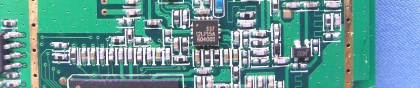
SAN-SURF200BG-C
Oct 02, 2006PePLink Surf 200BG / -AP
Equipment Class
DTS - Digital Transmission System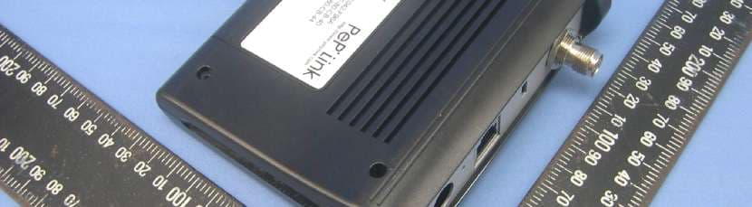
SAN-SURF200BG
Apr 19, 2006PePLink Surf 200BG
Equipment Class
DTS - Digital Transmission System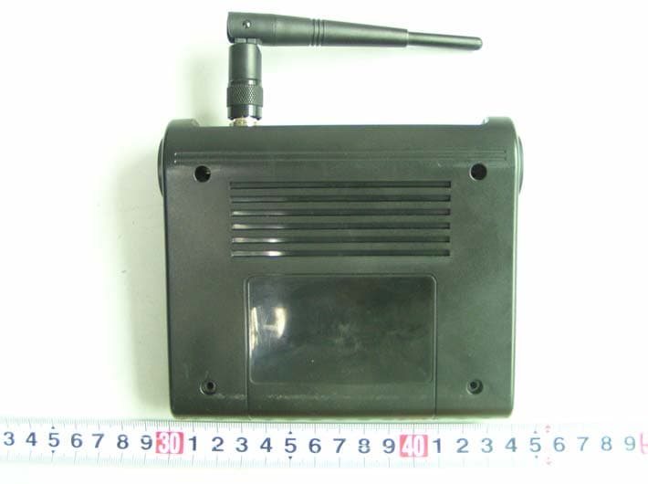
SAN24PS
Apr 10, 2006Intenet Access Router
Equipment Class
JBP - Part 15 Class B Computing Device Peripheral
SAN5405X
Aug 16, 2004LAN Network Device
Equipment Class
JBP - Part 15 Class B Computing Device Peripheral