SAN24PSIntenet Access Router
PePLink Ltd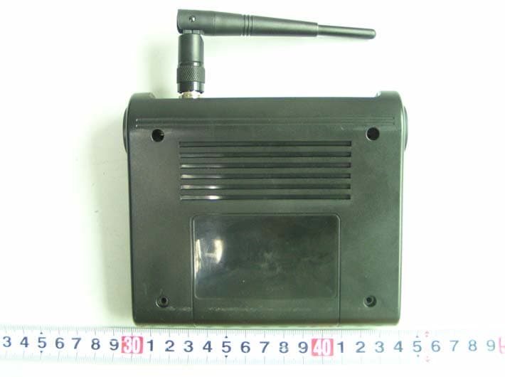
Click to zoom
Application Details
- Equipment Class
- JBP - Part 15 Class B Computing Device Peripheral
- Date of Grant
- Apr 10, 2006
- Application Purpose
- Original Equipment
- Date of Application
- Apr 10, 2006
- Equipment Note
- Intenet Access Router
- Company
- PePLink Ltd
- Country
- Hong Kong
Documents & Files
Document Text
Text extracted from the exhibit documents filed with the FCC. Open a document above to read the original.
Users Manual
PePLink Surf User’s Manual Document Version : 2.6 Firmware Version : 6.0.4 Date : 2006-02-10 PePLink Surf User’s Manual v2.6 Copyright © 1999-2006 PePLink Ltd. All Rights Reserved Page 2 of 30 Table of Content 1 Copyright 3 2 Disclaimer 3 3 Product Description 4 3.1 Features 4 3.2 Hardware Setup 5 3.3 LED Description 6 4 Using the PePLink Surf 7 4.1 First Time Setup 8 4.2 Settings Details 11 4.3 Advanced Settings: Port Forward 13 4.4 WPA/WPA2 with 802.1x Authentication 14 4.5 Test the Setup 17 4.6 Firmware Upgrade 18 4.7 Debug Page 19 4.8 Restore to Factory Defaults 20 4.9 System Settings 21 5 Appendix - Demo CA and Server Certification Generation Instructions 26 5.1 Prerequisite 26 5.2 Create your own Certificate Authority (CA) 26 5.3 Create a server certificate request from your servers 27 5.4 Sign the server certificate with your own CA 28 PePLink Surf User’s Manual v2.6 Copyright © 1999-2006 PePLink Ltd. All Rights Reserved Page 3 of 30 1 Copyright Copyright © 2006 by PePLink Ltd. The content of this documentation may not be reproduced in any part or as a whole without the prior written permission of PePLink Ltd. 2 Disclaimer PePLink does not assume any liability arising out of the application or use of any products, or software described herein. Neither does it convey any license under its patent right nor the patent rights of others. PePLink further reserves the right to make changes in any products described herein without notice. This documentation is subject to change without notice. PePLink Surf User’s Manual v2.6 Copyright © 1999-2006 PePLink Ltd. All Rights Reserved Page 4 of 30 3 Product Description PePLink Surf, formerly known as MANGA Surf, is a Wi-Fi Station Mode (Client) Router with WPA, WPA2 and 802.1x supplicant support. It is designed to act as a Wireless router which connects to Wireless Broadband Internet Service and allows LAN users to access the Internet via it. It associates to a service provider and authenticates using 802.1x (if needed) on start up. Upon successful association and authentication, it will acquire an IP address from the service provider using DHCP. A DHCP server is built-in on its LAN port. Network Address Translation is performed for all outbound connections. Thus it supports multiple terminals to access the Internet simultaneously. 3.1 Features • 10/100 Ethernet interface with auto-crossover detection • Reset button for restoring settings to factory defaults • Signal strength LED for showing the current signal strength • WPA/WPA2-Personal and WPA/WPA2-Enterprise support • Network Address Translation (NAT) routing • Built-in DHCP server • Inbound port range forwarding PePLink Surf User’s Manual v2.6 Copyright © 1999-2006 PePLink Ltd. All Rights Reserved Page 5 of 30 3.2 Hardware Setup 1. Attach the provided antenna to the left most antenna connector 2. Connect the LAN port to the computer’s Ethernet port with an Ethernet cable. 3. Connect the end of the included power adapter to the power socket (labeled “DC 5V”) on PePLink Surf. 4. Power on the power adaptor. PePLink Surf User’s Manual v2.6 Copyright © 1999-2006 PePLink Ltd. All Rights Reserved Page 6 of 30 3.3 LED Description LED Color Status Description Green On Power is on Power Off Power is off Green Solid Received signal is Excellent, Very Good and Good Green Blinking Received signal is Low Amber Blinking Received signal is Very Low Amber Solid No wireless signal is detected Status Off Booting up / Upgrading firmware Green On Ethernet is connected Green Blinking Sending/Receiving data LAN Off Ethernet is not connected Green On Associated with an access point Green Blinking Sending/Receiving data Wi-Fi Off Not associated with any access point This is the Signal Strength and Status LED state conversion table. Received Signal Strength Status LED Indication on the web based power meter > -70 Solid Green Excellent -70 to -74 Solid Green Very good -75 to -79 Solid Green Good -80 to -84 Blinking Green Low -85 to -87 Blinking Amber Very Low -87 to -89 Blinking Amber Very Low -89 < Blinking Amber Very Low PePLink Surf User’s Manual v2.6 Copyright © 1999-2006 PePLink Ltd. All Rights Reserved Page 7 of 30 4 Using the PePLink Surf You should set up your computer’s LAN interface to obtain an IP address automatically. If you do so, you should have set it up correctly. In order to do so, select the “Start” menu, “Control Panel” and then “Network Connections”. Right click on the “Local Area Connection” icon, choose “Properties”, double click on the item “Internet Protocol (TCP/IP)” from the list. On the screen, just set it as follows: Click the “OK” button to confirm the change. PePLink Surf User’s Manual v2.6 Copyright © 1999-2006 PePLink Ltd. All Rights Reserved Page 8 of 30 4.1 First Time Setup On your PC, start a web browser, e.g. Internet Explorer, Mozilla Firefox, etc. Visit an Internet web site. If you are not associated to an access point, you should be redirected to a logon page. Or you can go also go to this URL http://192.168.20.1/ The page will look like this. Once it is associated to an access point, you can also access the page from this URL: https://wan.ip.addr.here:8000/ Login ID and password are “admin” and “MSurf000”. PePLink Surf User’s Manual v2.6 Copyright © 1999-2006 PePLink Ltd. All Rights Reserved Page 9 of 30 Click the “Advanced Config” button to enter the parameters of the access point to associate to. You should see this screen: In the field “SSID” under Wireless Settings, input the access point’s SSID (sometimes it is called “network name”). According to the setting of the Access Point you are associating to, you may choose different “Authentication setting”. If “Static WEP key” or “WPA/WPA2-Personal” is selected, input the Encryption Key field as well. Click the “Save” button at the bottom to complete. You can now click the “Connect” link on the top bar and then click the “Connect” button to associate with the access point. There are also options of “802.1x with dynamic WEP ke…
Text truncated - open the document above for the full version.
External Photos
External Photos EUT-Front View EUT-Back View
ID Label/Location Info
ID Label Label FCC ID: SAN24PS (This device contains transmitter FCC ID: SWX-SR2)
ID Label/Location Info
ID Label/Location Label Location Information Specifications: Text is Black or white in color and is left justified. Labels are printed in indelible ink on permanent adhesive backing or silk-screened onto the EUT or shall be affixed at a conspicuous location on the EUT. Refer to the below arrow.
Operational Description
PePLink Pole Point Block Diagram and Technical Description Description of System The KS8695PX Integrated Multi-Port PCI Gateway solution provide a 10/100 TX/FX Auto MDI-X port connect to a Ethernet Network. On the other hand, the CPU also provide a 33 MHz PCI interface for a 802.11 b/g RF module, which can be used to connected a 802.11 b/g station. The IEEE802.11b/g WLAN MAC protocol is implemented in the Wi-Fi adapter's firmware. It supports basic service set (BSS) and independent basic service set (IBSS) operation under distributed coordination function (DCF). Low level protocol functions such as request to send (RTS)/clear to send (CTS) generation and acknowledgment, fragmentation and de-fragmentation, and automatic beacon monitoring are handled without host intervention. Active scanning is performed autonomously once initiated by a host command. Host interface command and status handshakes allow concurrent operations from multi-threaded I/O drivers. Access point features are implemented in the host system's firmware. It can act as an access point with multiple BSSID and ESSID. It bridges client traffic on the WLAN to the Ethernet port with configured VLAN tagged. It supports IEEE802.11i. A web based administration interface is provided for configuring the device.
Test Report
Note: The test report is specially limited to the above company and this particular sample only. It may not be duplicated without prior written consent of B ay Area Compliance Lab Corp. (ShenZhen). This report must not be used by the client to claim product certification, approval, or endorsement by NVLAP, NIST or any agency of the US Government. FCC PART 15 CLASS B EMI MEASUREMENT AND TEST REPORT For PePLink Ltd. 2302, Tai Tung Building 8 Fleming Road, Wanchai, Hong Kong FCC ID: SAN24PS March 9, 2006 This Report Concerns: Original Report Equipment Type: Internet Access Router Test Engineer: Lisa Zhu and Hansen Hu Report Number: RSZ06030202 Test Date: November 7-21, 2005 Reviewed By: Chris Zeng Prepared By: Bay Area Compliance Lab Corp. (ShenZhen) 6/F, the 3rd Phase of WanLi Industrial Building, ShiHua Road, FuTian Free Trade Zone, ShenZhen, Guangdong 518038, P.R.China Tel: +86-755-33320018 Fax: +86-755-33320008 PePLink Ltd. FCC ID: SAN24PS Report # RSZ06030202 Page 2 of 17 FCC Part 15 CLASS B Test Report TABLE OF CONTENTS GENERAL INFORMATION.......................................................................................................................................3 PRODUCT DESCRIPTION FOR EQUIPMENT UNDER TEST (EUT) ....................................................................................3 O BJECTIVE ...................................................................................................................................................................3 R ELATED S UBMITTAL ( S )/G RANT ( S ).............................................................................................................................3 T EST M ETHODOLOGY ..................................................................................................................................................3 TEST FACILITY.............................................................................................................................................................3 HOST SYSTEM CONFIGURATION LIST AND DETAILS....................................................................................................4 LOCAL SUPPORT EQUIPMENT LIST AND DETAILS........................................................................................................4 EXTERNAL I/O CABLE.................................................................................................................................................4 SYSTEM TEST CONFIGURATION ..........................................................................................................................5 JUSTIFICATION.............................................................................................................................................................5 EUT EXERCISE SOFTWARE..........................................................................................................................................5 SPECIAL ACCESSORIES.................................................................................................................................................5 BLOCK DIAGRAM/SCHEMATICS...................................................................................................................................5 EQUIPMENT MODIFICATIONS.......................................................................................................................................5 CONFIGURATION OF TEST SETUP.................................................................................................................................6 BLOCK DIAGRAM OF TEST SETUP................................................................................................................................6 SUMMARY OF TEST REPORT.................................................................................................................................7 §15.107 - CONDUCTED EMISSION ..........................................................................................................................8 M EASUREMENT U NCERTAINTY ....................................................................................................................................8 EUT SETUP..................................................................................................................................................................8 EMI TEST RECEIVER SETUP........................................................................................................................................9 TEST EQUIPMENT LIST AND DETAILS...........................................................................................................................9 TEST PROCEDURE........................................................................................................................................................9 TEST RESULTS SUMMARY............................................................................................................................................9 TEST DATA................................................................................................................................................................10 PLOT(S) OF TEST DATA..............................................................................................................................................10 §15.109 - RADIATED EMISSION.............................................................................................................................13 MEASUREMENT UNCERTAINTY..................................................................................................................................13 EUT SETUP................................................................................................................................................................13 EMI TEST RECEIVER SETUP...........................................................................................................................…
Text truncated - open the document above for the full version.
Test Setup Photos
Test Setup Photos Conducted Emission-Front View Conducted Emission-Side View Radiated Emission - Front View Radiated Emission – Rear View
Contact Information
Applicant
Antony Chong
Test Firm
Bay Area Compliance Laboratory Corp. (Shenzhen)John Chan
Technical Specifications
| # | Rule Parts | Frequency Range | Power Output |
|---|---|---|---|
| 1 | 15B | - | - |
Other Applications from PePLink Ltd
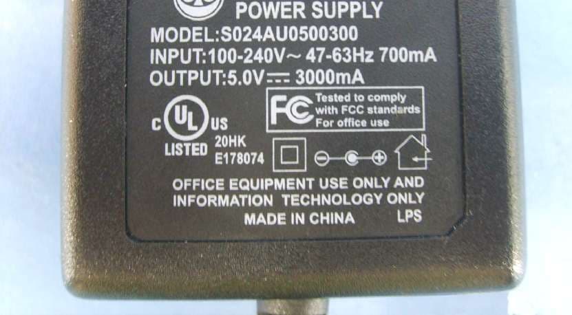
SAN-SURF200BG-C5
Oct 24, 2006PePLink Surf 200BG/200BG-AP
Equipment Class
DTS - Digital Transmission System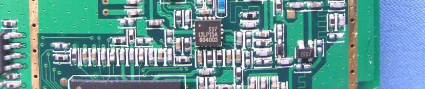
SAN-SURF200BG-C
Oct 02, 2006PePLink Surf 200BG / -AP
Equipment Class
DTS - Digital Transmission System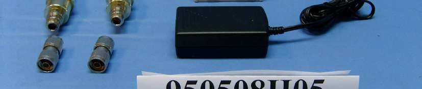
SAN-PP400BGX
Jun 05, 2006PePLink PolePoint Outdoor 400BG
Equipment Class
DTS - Digital Transmission System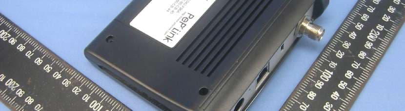
SAN-SURF200BG
Apr 19, 2006PePLink Surf 200BG
Equipment Class
DTS - Digital Transmission System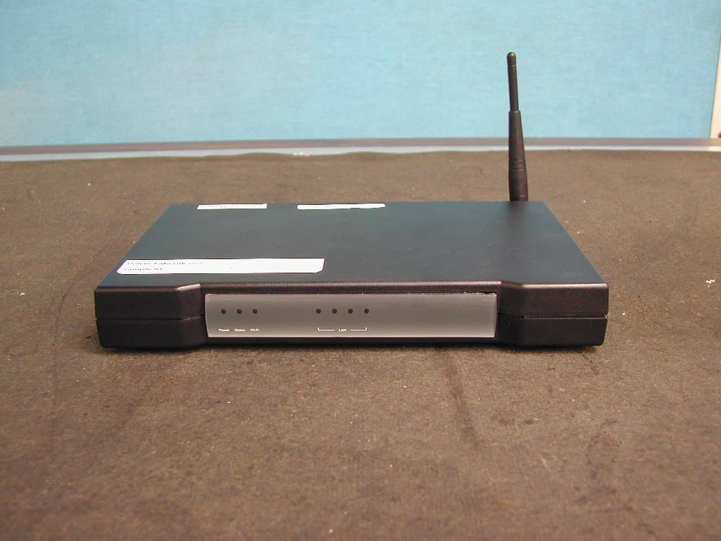
SAN5405X
Aug 16, 2004LAN Network Device
Equipment Class
JBP - Part 15 Class B Computing Device Peripheral