SAOTNN350APF-V1SMPS
Zalman Tech Co., Ltd.
Click to zoom
Application Details
- Equipment Class
- JBP - Part 15 Class B Computing Device Peripheral
- Date of Grant
- Jul 05, 2005
- Application Purpose
- Original Equipment
- Date of Application
- Jul 05, 2005
- Equipment Note
- SMPS
- Company
- Zalman Tech Co., Ltd.
- Country
- South Korea
Documents & Files
Document Text
Text extracted from the exhibit documents filed with the FCC. Open a document above to read the original.
Users Manual
18 Vin(230VAC) Form-factor factor switching Power Supply. Especially, It is applied to the line input capability, 2.1 AC INPUT LINE REQUIREMENTS +3.3VDC -12VDC +5VSB 5% Efficiency 350. Watt max Continuous 2. ELECTRICAL SPECIFICATION 1. INTRODUCTION The "TNN350APF-V1" is a Power Supply designed to be used "ATX12V" form factor The scope of this document is limited to the requirements of "ATX12V" PC form 5% 5% MODEL NO: TNN350APF-V1 REV.0 POWER 8 ZALMAN SPECIFICATION Vin(230VAC) 47 Vin(115VAC) UNITParameter Vin FREQUENCY MIN VACrms VACrms 115 230 90 180 MAX PAGE: 1/9 A A Hz 0A Output voltage Requla -tion +12VDC1 +5VDC 5% 5% +12VDC25% 2.0A Max load(Amps) 10.0A 20.0A 15.0A ATX/ATX12V 380. Watt max peak Peak current(Amps)Min load(Amps) 80% at Full load server computer systems 1.1 SCOPE DATE: 2005. 1. 17 1A 0.5A 0.5A remote ON/OFF, cooling, standby voltage("VSB") and electrical characteristics. - 135 265 63 15 1A 0A Vin(115VAC) NOM 2.5A 20.0A 0.3A +3.3VDC"0.5 " +12VDC +5VSB 0.5+5VDC3A 1.0-9A DATE: 2005. 1. 17 "2.5A2A- "2.5A2.0A Amps5A - - " - 1.0 0.0 0.0 "0.3 " - 14.1A- " Range 2) Maximum +5V and +3.3V output power shall not exceed 120Watts. Parameter +12VDC18A- MAX 4) It shall not exceed 17 seconds in duration at Total +12VDC1, +12VDC2 output power, 300Watts. " 1.012A" +12.6Volts +4.75 -0.5 +12VDC2 +3.3VDC +5VSB 1) Maximum continuous total DC output power shall not exceed 350Watts. +5.00Volts +3.47 UNIT Volts-12VDC +4.75+5.00 +12.00+12VDC1 +5VDC Parameter +5.25Volts -13.20 +5.25 10A 1.0Amps (High- 5A ZALMAN SPECIFICATIONPAGE: 2/9 +5VSB 0.3-0.0-12VDC 0.0 MODEL NO: TNN350APF-V1 REV.0 +3.3VDC +5VDC +12VDC (Normal Load) Range 2 0.5 Load) 5) Output voltage of +5VSB shall be maintained within the power shut down. 3) Maximum Peak Total DC output power shall not exceed 380Watts. 2.2.2 DC output CURRENT NOMMINPEAK Range 1 UNIT TEST POINT : OUTPUT CONNECTOR LOAD TERMINALS. MAXMINNOM Volts 2.1.1 INRUSH CURRENT Max. inrush current shall not exceed 60 CA(Peak to Peak). 2.2 DC OUTPUT REQUIREMENTS 2.2.1 OUTPUT REQUIREMENTS -12.00-10.80 +3.14 +11.4 -12VDC +3.30 +12VDC2+11.4+12.00+12.6Volts AC INPUT PSU LOAD 80" " UNIT 20MHz. a 0.1uF Ceramic capacitors at each output with measuring band width from DC to +3.3VDC +5VDC1.0%- -1.0% 1.0%- V return AC NEUTRAL -12VDC mVp-p1.0%-80 ParameterRangeMIN . The measurements should be made by crossing a 10uF electrolytic capacitor and NOR 2.2.4 OUTPUT RIPPLE/NOISE AC LIVE SCOPE " 1) The power supply at full load provide AC/DC conversion efficiency 80% minimum. AC GROUND 120 80 10uF . Load Slew Rate : 0.5A/us 2.2.5 Dynamic Loading V OUT +5VSB1.0% 2.2.3 EFFICIENCY +12VDC MAX 0.1uF 50"- PAGE: 3/9ZALMAN SPECIFICATION MODEL NO: TNN350APF-V1 REV.0DATE: 2005. 1. 17 Capacitive Load 0.5A/us 1000uF 1000uF 1000uF 1uF 0.5A/us +5VSB Step Load SizeLoad Slew Rate 30% of max load 30% of max load 25% of max load 0.5A/us 0.5A/us 65% of max load Output +3.3V +5V +12V1,+12V2 T2T3 ZALMAN SPECIFICATIONPAGE: 4/9 MODEL NO: TNN350APF-V1 REV.0 PS_ON PS_OFF * PW-OK sense level : 95% of nominal 2.3.1 REMOTE ON/OFF CONTROL DATE: 2005. 1. 17 2.3.2 POWER UP DELAY . When PS-ON is pulled to TTL low, the DC outputs are to be enabled. . When PS-ON is pulled to TTL high or open circuited, the DC outputs are to be disabled. Turn ON/OFF delay >- 1000ms The power supply DC outputs (with the exception of +5VSB) shall be enabled with AC power is present. an active-low, TTL-compatible signal("PS-ON"). The +5VSB is on whenever the DC Enable 95% 10% T4 2.3 TIMING / HOUSE KEEPING PWR-OK The output voltages shall rise from <10% of nominal to within the regulation ranges specified in sec 2.2.1 within 5 to 70ms. MinUnitMax . Power Down Warning : 1ms<T4<200ms V 2.3.4 VOLTAGE HOLD-UP TIME The power supply shall maintain output regulation per section 2.2.1 despite a loss of input power at the low-end nominal range at maximum continuous Parameter 2.4 OUTPUT PROTECTION 2.4.1. OVER VOLTAGE PROTECTION +5VDC5.746.37.0 +12VDC13.41515.6V Nom DATE: 2005. 1. 17 . +5V : 25A~ Test Condition : Output Full Load . +3.3V : 25A~ . +12VDC1 : 18A~ PAGE: 5/9ZALMAN SPECIFICATION MODEL NO: TNN350APF-V1 REV.0 . +12VDC2 : 18A~ . Logic level Low : <0.4V 4mA +3.3VDC3.764.24.3 *Change latch mode at above voltage in power supply unit. 2.4.2. SHORT CIRCUIT PROTECTION . Shutdown or latch at short +3.3, +5V and +12V. . No damage in compenents, PCB trace connector at continous shout. . The maximum short circuit current shall not exceed 240VA. 2.4.3. OVER POWER PROTECTION V V output load as specified in section 1.1 for a minimum 17ms. 2.3.3 POWER GOOD SIGNAL, POK . Logic level High :Between 2.4VDC and 5VDC output while sourcing current, 2mA . Signal Type : Open Collector +5VDC, TTL compatible. . POK Delay : 200mS<T3<1000ms . Primary to Secondary : 500VDC 100 . Primary to FG : 500VDC 100 DATE: 2005. 1. 17 ZALMAN SPECIFICATIONPAGE: 6/9 MODEL NO: TNN350APF-V1 REV.0 Shall be 1.0mA Maximum at 220VAC Input On 2.4.11. LEAKAGE CURRENT(IEC950) . The Maximum Leakage Current Following The Frame / AC Sine Conductor 2.4.10. INSULATION VOLTAGE WITHSTAND 2.4.6. MEAN TIME BETWEEN FAILURES . Operating Time 50,000HR at 25. 2.4.7. This power supply shall comply with the followings. . CSA C22.2 NO220 & CSA Bulletin 1402C, Level3 Off Control Signal Logic " Low" Logic " High" Output Status 2.4.9. POWER SWITCH On/Off TEST 2.4.4 DC INPUT PROTECTION . VDE 0806, EN60950 A3 . IEC950 2.4.5. BURN-IN Primary lot is output full load at 55 24HR . UL1950 . Use proper fuse for DC input over current protection. 2.4.8. EMI . VDE 0871/6.78 Class B . FCC Part 15 Sub Part J, Class B . Operating : 5 ~ 40 2.4.13. TEMPRATURE RANGE . Storage : -20 ~ 85 2.4.12. DIELECTRIC STRENGTH . Between Input and Output : 1500VAC 10mA 1min or 1800VAC 10mA 3sec . Between Input and FG : 1500VAC 10mA 1min or 1800VAC 10mA 3sec . Polarity : +, - . Phase : 0 - 360 . Mode : Common, Normal 2.4.14. HUMIDITY RANGE . Operating : 20% ~ 80% . Storage : 10% ~ 95% . The power Supply Must not generate Acoustic Noise in excess of…
Text truncated - open the document above for the full version.
Block Diagram
BLOCK DIAGRAM AC INPUT LINEFILTER 돌입전류방지회로 BRIDGERECTIFIER +5V STBYSWITCHING PFC CIRCUIT PFC CONTROL +24V INV CONVERTER OUTPUTFILTER OUTPUTFILTER +24V INVSWITCHING MULTISWITCHING +5V STBY CONVERTER OUTPUTFILTER -12V CONVERTER +3.3V CONVERTER OUTPUTFILTER OUTPUTFILTER +12V1OUTPUT +12V2OUTPUT +5VOUTPUT -12VOUTPUT +3.3VOUTPUT WT7517 OUTPUT CONTROL(UVP,OVP,SCP) & INRUSHON/OFF CONTROL VOLTAGEDETECT INRUSH ON/OFFCONTROL INTERFACE +5V CONVERTER +5V S/BOUTPUT RESONANTCONTROL PWM CONTROL MAGAMPCONTROL PWM CONTROL OUTPUTON/OFFCONTROL
External Photos
Test report Our reference : KEL05-F03030 Page : B1 of Appendix Issued date : 2005-06-28 Appendix-B : External Photographs of E.U.T <FRONT VIEW OF EUT> Korea EMC Laboratory <REAR VIEW OF EUT>
ID Label/Location Info
Test report Our reference : KEL05-F03030 Page : D1 of Appendix Issued date : 2005-06-28 Appendix-D : FCC ID label location information and Sample - FCC ID label location information The label included following statement will be attached on the bottom side of product. - FCC ID label sample Korea EMC Laboratory
Internal Photos
Test report Our reference : KEL05-F03030 Page : C1 of Appendix Issued date : 2005-06-28 Appendix-C : Internal Photographs of E.U.T <INTERNAL VIEW OF E.U.T> Korea EMC Laboratory Test report Our reference : KEL05-F03030 Page : C2 of Appendix Issued date : 2005-06-28 <FRONT VIEW OF SMPS BOARD> Korea EMC Laboratory Test report Our reference : KEL05-F03030 Page : C3 of Appendix Issued date : 2005-06-28 <REAR VIEW OF SMPS BOARD> Korea EMC Laboratory
Test Report
390 Bora-ri, Giheung-eup, Yongin-si, Gyeunggi-do, Republic of Korea (Zip Code:449-904) TEL : (82)31-286-5881 FAX : (82)31-286-2661 http://www.koreaemc.co.kr [email protected] CERTIFICATE OF COMPLIANCE (CLASS B) CERTIFICATION OF COMPLIANCE is hereby issued to the named Applicant and is VALID ONLY for the equipment identified below: Date of Tested : June. 27. 2005 Applicant’s Name : Zalman Tech Co., Ltd. Applicant’s Address : 1007 Daer Yung Techno Town III 48 Gasan-Dong, Gumchun-Gu, Seoul, Korea Manufacturer’s Name : Acrotech Co., Ltd. Manufacturer’s Address : R&D Center 488-1 Yulam-Ri, Paltan-Myeon, Hwasung-Si, Gyonggi-Do, Korea Declares that the product Product Description : SMPS Brand Name : Zalman Model Number : TNN350APF-V1 FCC ID : SAOTNN350APF-V1 Conforms to FCC Rules and Regulations Part 15 Subpart B requirements. This product herewith complies with the requirements of the FCC Rules and Regulations as listed below: Part 15.107: Conducted Emissions. Part 15.109: Radiated Spurious Emissions. TESTED and CERTIFIED by: KOREA EMC LABORATORY 390 Bora-ri, Giheung-eup, Yongin-si, Gyeunggi-do, Republic of Korea (Zip Code:449-904) Date :June. 28. 2005 Report No :KEL05-F03030 Authorized Signature : M. S. CHO / President Test report Our reference : KEL05-F03030 Page : 2 of 14 Issued date : 2005-06-28 TABLE OF CONTENTS DESCRIPTION Page 0. VERIFICATION OF COMPLIANCE 3 1. GENERAL INFORMATION 1.1 Product Description 4 1.2 Related Submittal(s)/Grant(s) 4 1.3 Tested System Details 4 1.4 System Configuration 4 1.5 General Setup of the test Shield room 5 1.6 Test Facility 5 2. Measurement Procedure 2.1 System test configuration 6 2.1.1 Video mode Justification 6 2.1.2 EUT Exercise S/W 6 2.2 Special Accessories 6 2.3 Equipment Modification 6 2.4 Connected Cable 6 2.5 System Configuration Diagram 6 2.6 Preliminary testing 7 2.7 Shielded Enclosure 7 2.8 Data Reporting Format 7 2.9 Operating Condition 7 2.10 Conditioning of the EUT 7 2.11 Power Line Conducted Emissions 8 2.12 Open field Radiated Emissions Tests 8 3. Measurement Data 3.1 Conducted Emission Data 9 3.2 Conducted Emission Graph 10-11 3.3 Radiated Emission Data 12 3.4 Summary 13 4. Labeling Requirement 14 Appendix - A : Test set-up Photographs (Conducted and Radiated) - B : External Photographs of E.U.T - C : Internal Photographs of E.U.T - D : FCC ID label location information and sample - E : Block Diagram Korea EMC Laboratory - F : User’s Manual Test report Our reference : KEL05-F03030 Page : 3 of 14 Issued date : 2005-06-28 0 . VERIFICATION OF COMPLIANCE Equipment Under Test : SMPS Mo d e l N u m b e r : TNN350APF-V1 Serial Number : Representative manufacturing sample Manufacturer : Acrotech Co., Ltd. R&D Center 488-1 Yulam-Ri, Paltan-Myeon, Hwasung-Si, Gyonggi-Do, Korea Type of Test : FCC CLASS B Report Number : KEL05-F03030 Date Tested : June. 27. 2005 Tested By : S.J.KIM The results show that the sample equipment tested as described in this reports is in compliance with the CLASS B conducted and radiated emission limits of FCC Rules Part 15, Subpart B. Korea EMC Laboratory Test report Our reference : KEL05-F03030 Page : 4 of 14 Issued date : 2005-06-28 1. GENERAL INFORMATION 1.1 PRODUCT DESCRIPTION The TNN350APF-V1 is a SMPS made by Acrotech Co., Ltd. in Korea. Refer to the user's manual for more information. AC INPUT LINE REQUIREMENTS Parameter MIN NOM MAX UNIT Vin(115VAC) 90 115 135 VACrms Vin(230VAC) 180 230 265 VACrms Vin FREQUENCY 47 - 63 Hz Vin(115VAC) - - 15 A Vin(230VAC) - - 8 A OUTPUT REQUIREMENTS Parameter MIN NOM MAX UNIT +12VDC1 +11.4 +12.00 +12.6 Volts +12VDC2 +11.4 +12.00 +12.6 Volts +5VDC +4.75 +5.00 +5.25 Volts +3.3VDC +3.14 +3.30 +3.47 Volts -12VDC -10.80 -12.00 -13.20 Volts +5VSB +4.75 +5.00 +5.25 Volts * Dimension : 294 x 200 x 67 mm * E.U.T uses 67 kHz(Standby) Clock. 1.2 Related Submittal(s)/Grant(s) N/A 1.3 Tested System Details Type Model Name FCC ID Serial NO Manufacturer SMPS TNN350APF-V1 SAOTNN350APF-V1 Representative manufacturing sample Acrotech Co., Ltd. Multi Meter 82018 - NONE CRAFTSMAN 1.4 System Configuration Korea EMC Laboratory Type Model Name Serial NO Manufacturer Remark SMPS B/D TNN350APF-V1 NONE Acrotech Co., Ltd. Korea Test report Our reference : KEL05-F03030 Page : 5 of 14 Issued date : 2005-06-28 1.5 General Set-up of the Test Shielded Room The EUT was set up in accordance with the suggested configuration given in FCC measurement Procedure ANSI C63.4-2003. The measurement are performed in the shielded room which dimension is 3.0*7.0*2.5(m). The EUT was placed on a non conductive table which is 1.0*1.5(m), 80 cm above an earthed ground plane and is kept at least 1m from any other earthed ground plane except the rear of table top being removed 40 cm from a vertical conducting plane. Power to the EUT was provided through the LISN(NSLK8128, SCHWARZBECK) which has the Impedance vs Frequency Characteristic in accordance with the conducted setup photographs in Appendix-A Impedance Characteristic of LISN. Peripheral equipment required to provide a functional system(support equipment) for EUT testing was powered through another LISN(KNW-407, KYORITSU). Power to the LISN was filtered to eliminate ambient signal interference. A coaxial type connector which provides a 50 Ohm terminating impedance was provided for the test instrument. The excess length of the power cord was wrapped in the two non metallic pegs attached to the top of the LISN. The two pegs are 9 cm high, approximately 2.0 cm in diameter and that are spaced 6 cm on the center apart. 1.6 Test Facility Location: Korea EMC Laboratory 390 Bora-ri, Giheung-eup, Yongin-si, Gyeunggi-do, Republic of Korea (Zip Code:449-904) Site : - 3 m/10 m Open Area Testing Site No.1 - 3 m Semi-Anechoic Chamber No.1 - Shielded Room No.1 The Open Field Radiated and Indoor Line Conducted sites are constructed and calibrated to meet the FCC requirements in documents ANSI C63.4-2003. Korea EMC Lab. was refiled in FCC in April. 13. 2005. Description Model Manufacturer Se…
Text truncated - open the document above for the full version.
Test Setup Photos
Test report Our reference : KEL05-F03030 Page : A1 of Appendix Issued date : 2005-06-28 Appendix-A : Test Setup Photographs - Conducted Setup Photographs LINE CONDUCTED SETUP PHOTOGRAPH - FRONT VIEW LINE CONDUCTED SETUP PHOTOGRAPH - REAR VIEW Korea EMC Laboratory Test report Our reference : KEL05-F03030 Page : A2 of Appendix Issued date : 2005-06-28 - Radiated Setup Photograph RADIATED EMISSION SETUP PHOTOGRAPH - FRONT VIEW RADIATED EMISSION SETUP PHOTOGRAPH - REAR VIEW
Contact Information
Applicant
Sang Ju Lee(Technical Team / Assistant Manager)
Test Firm
Korea EMC Laboratory Co., LtdMan-sung Cho
Technical Specifications
| # | Rule Parts | Frequency Range | Power Output |
|---|---|---|---|
| 1 | 15B | - | - |
Other Applications from Zalman Tech Co., Ltd.

SAOZMWE450
Jan 16, 2014WiFi Storage Device
Equipment Class
DTS - Digital Transmission System
SAOZM600-HP
Jan 01, 2007Power supply unit
Equipment Class
JBC - Part 15 Class B Computing Device/Personal Computer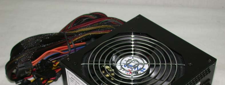
SAOZM360B-APS
Jan 29, 2006Internal power supplies used with Class B PC
Equipment Class
JBP - Part 15 Class B Computing Device Peripheral
SAOZM460B-APS
Jan 29, 2006Internal power supplies used with Class B PC
Equipment Class
JBP - Part 15 Class B Computing Device Peripheral
SAOZM460-APS
Apr 26, 2005Power Supply
Equipment Class
JBP - Part 15 Class B Computing Device Peripheral