SAOZM360B-APSInternal power supplies used with Class B PC
Zalman Tech Co., Ltd.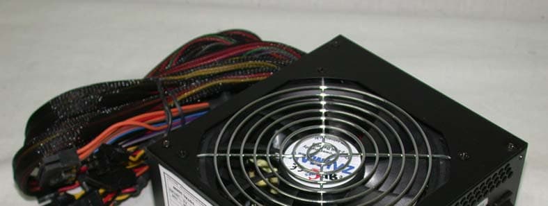
Click to zoom
Application Details
- Equipment Class
- JBP - Part 15 Class B Computing Device Peripheral
- Date of Grant
- Jan 29, 2006
- Application Purpose
- Original Equipment
- Date of Application
- Jan 29, 2006
- Equipment Note
- Internal power supplies used with Class B PC
- Company
- Zalman Tech Co., Ltd.
- Country
- South Korea
Documents & Files
Document Text
Text extracted from the exhibit documents filed with the FCC. Open a document above to read the original.
Users Manual
SPECIFICATION ZM360B-APS 9PA4601100 Main Feature: Low Noise High Efficiency Active PFC Circuit Full Range Input DEC 21, 2005 REV:01 MODEL: ZM360B-APS Revision History Rev Description Date Author 1.0 Released 2005/12/21 1. GENERAL DESCRIPTION AND SCOPE This is the specification of Model ZM360B-APS; AC-line powered switching power supply with active PFC (Power Factor Correction) circuit, meet EN61000-3-2 and with Full Range Input features. The specification below is intended to describe as detailedly as possible the functions and performance of the subject power supply. Any comment or additional requirements to this specification from our customers will be highly appreciated and treated as a new target for us to approach. 2. REFERENCE DOCUMENTS The subject power supply will meet the EMI requirements and obtain main safety approvals as following: 2.1 EMI REGULATORY - FCC Part 15 Subpart J, Class ‘B’ 115 Vac operation. - CISPR 22 Class ‘B’ 230 Vac operation. 2.2 SAFETY - NEMKO EN 60950 - TUV EN60950 OR VDE EN60950 -CSA-C22.2 NO. 60950 -IEC 60950 - UL 60950 - CE : EN 55022:1998+A1: 2000, Class B EN 61000-3-2: 2000 EN 61000-3-3: 1995+A1: 2001 CISPR22: 1997+A1: 2000, Class B AS/NZS CISPR 22: 2002, Class B Table. 1 Loading Table for Efficiency Measurements 360W(loading shown in Amps) Loading +12V1 +12V2 +5V +3.3V -12V +5Vsb Full 11.0 13.0 9.0 10.0 0.3 2.0 Typical 5.0 9.0 3.0 5.0 0.1 1.0 Light 3.0 3.5 1.0 2.0 0.0 1.0 Table 2. Minimum Efficiency Vs Load Loading Voltage Full load Typical load Light load Required Minimum Efficiency 115V 75% 75% 70% Required Minimum Efficiency 230V 80% 80% 75% 3.5 MECHANICAL SPECIFICATIONS The mechanical drawing of the subject power supply, which indicate the form factor, location of the mounting holes, location, the length of the connectors, and other physical specifications of the subject power supply. Please refer to the attachment drawing. 4.0. OUTPUT ELECTRICAL REQUIREMENTS 4.1 OUTPUT VOLTAGE AND CURRENT RATING Output MINIMUM LOAD NORMAL LOAD MAXIMUM LOAD LOAD REG LINE REG. RIPPLE&NOISE RIPPLE +3.3V 0.5A 11A 22A ±5% ±1% 100mV P-P 50mV P-P +5V 0.3A 10.5A 21A ±5% ±1% 100mV P-P 50mV P-P +12V1 1A 5A 11 A ±5% ±1% 200mV P-P 120mV P-P +12V2 1A 7.5A 15A ±5% ±1% 200mV P-P 120mV P-P -12V 0A 0.15A 0.5A ±10% ±1% 200mV P-P 120mV P-P +5VSB 0A 1.25A 2.5A ±5% ±1% 100mV P-P 50mV P-P ( 1 ) +3.3V & +5V total output not exceed 150W. ( 2 ) +3.3V & +5V & +12V1 & +12V2 total output not exceed 347W ( 3 ) total output for this subject power supply is 360 watts ( 4 ) +5VSB Peak current loading is 3A , shall be supported for a minimum of 500m second. .4.2. LOAD CAPACITY SPECIFICATIONS The cross regulation defined as follows, the voltage regulation limits DC include DC Output ripple & noise. LOAD STM. +3.3V +5V +12V1 DC +12V2 DC -12V +5VSB FULL LOAD MHMMHH 13.4A 21A 7.6A 7.6A 0.5A 2.5A FULL LOAD HMMMHH 22A 15.4A 7.6A 7.6A 0.5A 2.5A +3.3V MAX other MIN HLLLLL 22A 3A 3A 3A 0A 0A +5V MAX Other MIN LHLLLL 0.5A 15A 1.5A 1.5A 0A 0A +12V1&+12V2 MAX Other MIN LLHHLL 0.5 A 2.0A 10A 15A 0A 0A -12V MAX other MIN LLLLHL 0.5A 0.3A 1A 1A 0.5A 0A +5VSB MAX other MIN LLLLLH 0.5A 0.3A 1A 1A 0A 2A ALL MIN LLLLLL 0.5A 0.3 A 1A 1A 0A 0A 4.3. HOLD-UP TIME (@FULL LOAD) 115V / 60Hz : 17 mSec. Minimum. 230V / 50Hz : 17 mSec. Minimum. The output voltage will remain within specification, in the event that the input power is removed or interrupted, for the duration of one cycle of the input frequency. The interruption may occur at any point in the AC voltage cycle. The power good signal shall remain high during this test. 4.4.OUTPUT RISE TIME (10% TO 95% OF FINAL OUTPUT VALUE, @FULL LOAD) 115V-rms or 230V-rms + 3.3Vdc : 20ms Maximum + 5Vdc : 20ms Maximum + 12Vdc : 20ms Maximum -12Vdc : 20ms Maximum + 5Vsb : 25ms Maximum 4.5.OVER VOLTAGE PROTECTION Voltage Source Protection Point +3.3V 3.76V-4.8V +5V 5.6V-7.0V +12V 13.0V-15.6V 4.6.OVER-CURRENT PROTECTION OUTPUT VOLTAGE Max. overcurrent limit +3.3V 45.0A +5V 45.0A +12V1 DC 15.0A +12V2 DC 20.0A 4.7.SHORT CIRCUIT PROTECTION Output short circuit is defined to be a short circuit load of less than 0.1 ohm. In the event of an output short circuit condition on +3.3V, +5V or +12V output, the power supply will shutdown and latch off without damage to the power supply. The power supply shall return to normal operation after the short circuit has been removed and the power switch has been turned off for no more than 2 seconds. In the event of an output short circuit condition on –12V output, the power supply will not be damaged. The power supply shall return to normal operation as soon as the short circuit has been removed. and the power switch has been turned off for no more than 2 seconds. 4.8. POWER SIGNAL 5.0 FAN NOISE REQUIREMENTS 5.1.The subject power supply is cooled by a self-contained, 120mm, 12VDC fan. 1. FAN NOISE 2. ENVIRONMENTAL REQUIREMENTS AC INPUT FULL (Table.1) TYPICAL (Table.1) LIGHT (Table.1) 115V NOISE≦30dB NOISE≦25dB NOISE≦22dB 230V NOISE≦30dB NOISE≦25dB NOISE≦22dB The power supply will be compliant with each item in this specification for the following Environmental conditions. 6.1. TEMPERATURE RANGE 6.2. HUMIDITY 6.3. VIBRATION The subject power supply will withstand the following imposed conditions without experiencing non-recoverable failure or deviation from specified output characteristics. Vibration Operating – Sine wave excited, 0.25 G maximum acceleration, 10-250 Hz swept at one octave / min. Fifteen minute dwell at all resonant points, where resonance is defined as those exciting frequencies at which the device under test experiences excursions two times large than non-resonant excursions. Plane of vibration to be along three mutually perpendicular axes. 6.4 GROUND LEAKAGE CURRENT The power supply groud leakage current shall be less than 3.5 mA. 6.5 RELIABILITY The power supply reliability,when calculated by MIL-HDBK-217;latest revision, are exceed 100,000 hours with all output at maximum load and an ambient temperature of 25°C. 6.6 DIELECTRIC STRE…
Text truncated - open the document above for the full version.
Block Diagram
Appendix E. Block Diagram Report no. ETLE051226.030, Page E1 of E1 Head Office : # 371-51 Kasan-Dong, Keumcheon-ku, Seoul, 153-803, Korea / Tel : 82-2-858-0786, Fax : 82-2-858-0788 EMC Lab : #584 Sangwhal-ri, Kanam-myon, Yoju-kun, Kyounggi-do, 469-885, Korea Tel:82-31-885-0072, Fax:82-31-885-0074 ETLQP-21-F22-0
External Photos
Appendix C. External Photographs Front View of EUT Rear View of EUT Report no. ETLE051226.030, Page C1 of C1 Head Office : # 371-51 Kasan-Dong, Keumcheon-ku, Seoul, 153-803, Korea / Tel : 82-2-858-0786, Fax : 82-2-858-0788 EMC Lab : #584 Sangwhal-ri, Kanam-myon, Yoju-kun, Kyounggi-do, 469-885, Korea Tel:82-31-885-0072, Fax:82-31-885-0074 ETLQP-21-F22-0
ID Label/Location Info
Appendix A. FCC ID Label and Location Product Label Sample with FCC Label information Following is a sample copy of the label that will be placed on the rear cabinet of the product. The FCC ID Label and compliance statement are marked in the product label. Zalman Tech Co., Ltd. PC Type SMPS Report no. ETLE051226.030, Page A1 of A2 Head Office : # 371-51 Kasan-Dong, Keumcheon-ku, Seoul, 153-803, Korea Tel : 82-2-858-0786 Fax : 82-2-858-0788 EMC Lab : #584 Sangwhal-ri, Kanam-myon, Yoju-kun, Kyounggi-do, 469-885, Korea Tel:82-31-885-0072, Fax:82-31-885-0074 ETLQP-21-F22-0 FCC ID : SAOZM360B-APS Model No : ZM360B-APS POWER : AC 100 - 240 V, 5 - 3 A, 50 - 60㎐ Serial No : N/A This device complies with part 15 of the FCC Rules. Operation is subject to the following two conditions: (1) This device may not cause harmful interference, and (2) This device must accept any interference received, including interference that may cause undesired operation. Manufacturer: SPI Electronic Co., Ltd. Made in China Appendix A. FCC ID Label and Location Label Location The label shown shall be permanently affixed at a conspicuous location on the device and be readily visible to the user at the time purchase.(Labeling requirements per 2.925) Label here Report no. ETLE051226.030, Page A2 of A2 Head Office : # 371-51 Kasan-Dong, Keumcheon-ku, Seoul, 153-803, Korea Tel : 82-2-858-0786 Fax : 82-2-858-0788 EMC Lab : #584 Sangwhal-ri, Kanam-myon, Yoju-kun, Kyounggi-do, 469-885, Korea Tel:82-31-885-0072, Fax:82-31-885-0074 ETLQP-21-F22-0
Internal Photos
Appendix D. Internal Photographs View of Inside Report no. ETLE051226.030, Page D1 of D3 Head Office : # 371-51 Kasan-Dong, Keumcheon-ku, Seoul, 153-803, Korea / Tel : 82-2-858-0786, Fax : 82-2-858-0788 EMC Lab : #584 Sangwhal-ri, Kanam-myon, Yoju-kun, Kyounggi-do, 469-885, Korea Tel:82-31-885-0072, Fax:82-31-885-0074 ETLQP-21-F22-0 Appendix D. Internal Photographs Component side view of Main power board Report no. ETLE051226.030, Page D2 of D3 Head Office : # 371-51 Kasan-Dong, Keumcheon-ku, Seoul, 153-803, Korea / Tel : 82-2-858-0786, Fax : 82-2-858-0788 EMC Lab : #584 Sangwhal-ri, Kanam-myon, Yoju-kun, Kyounggi-do, 469-885, Korea Tel:82-31-885-0072, Fax:82-31-885-0074 ETLQP-21-F22-0 Appendix D. Internal Photographs Solder side view of Main power board Report no. ETLE051226.030, Page D3 of D3 Head Office : # 371-51 Kasan-Dong, Keumcheon-ku, Seoul, 153-803, Korea / Tel : 82-2-858-0786, Fax : 82-2-858-0788 EMC Lab : #584 Sangwhal-ri, Kanam-myon, Yoju-kun, Kyounggi-do, 469-885, Korea Tel:82-31-885-0072, Fax:82-31-885-0074 ETLQP-21-F22-0
Operational Description
Power supply operation description ZM460B-APS and ZM360B-APS are developed with the SMPS (SWITCHING MODE POWER SUPPLY) technology. This technology is a method for outputting voltage by dividing the high input voltage into regular periods with the use of TR by utilizing the input voltage with SWITCHING technology and coils. Such method improves efficiency (75%), but NOISE is emitted due to SWITCHING. The diagram shown above is the brief circuitry of the AC-DC POWER that operates as described below: At location ①, CAP and LINE FILTER are supplemented for the stabilization of AC input voltage, and in case of VARISTER, it is used for preventing the serge of input voltage At location ②, AC input voltage is transformed into high DC voltage through the BRIDGE-DIODE. The DC power of this voltage is made smooth with the use of a condenser. Location ③ is the necessary IC for controlling the PWM method, as the element for controlling the motion of AC-DC POWER SUPPLY. Voltage is supplied by going through the number 6’s DIODE after the initial voltage is inputted through the resistor. The PWM signal is sent after going through the number 4 TR after the internal comparator compares the amplitude change regarding the output voltage that is entered into number 9. Location ④ switches the high DC voltage after receiving the PWM signal. TR quantity is formed according to the high voltage quantity and current quantity. Smaller internal resistance allows less heat to be generated during SWITCHING. The current trend is using the POWER MOSFETs. Location ⑤ is the device for stopping POWER’s motion when more current enters the OCP than the fixed amount of current. It is supplemented with a protective circuit for preventing damage to the electronic device when sudden high current is flown into the OCP. Location ⑥ supplies secondary power to the IC through trans. Location ⑦ turns the alternating voltage into DC voltage by rectifying it in the DIODE after receiving n1’s alternating voltage as an appropriate n2’s alternating voltage. For n2’s DIODES, great amount of heat is generated, and various elements are available such as SHOTTKY, FAST RECOVERY, and ULTRA FAST RECOVERY. Location ⑧ is the FILTER for the rectified DC voltage’s smoothing, ripple, and noise reduction. Location ⑨ stabilizes the output DC voltage’s rate of change by transferring the output DC voltage to the n1’s IC through the OPTO COUPLER. Location ⑩ transfers the output DC voltage to number 9 after detecting its changes. KA431 is usually used. Location ⑪ is the high-voltage prevention circuit that acts as a protective circuit to prevent the POWER’s motion if the output voltage is greater than the fixed voltage amount.
Test Report
This report only responds to the tested sample and may not be reproduced, except in full, without written approval of the ETL Inc. www.etl.re.kr E-RAE Testing Laboratory Electromagnetic Emission FCC MEASUREMENT REPORT CERTIFICATION OF COMPLIANCE FCC Part 15 Certification Measurement This PC Type SMPS, Model ZM360B-APS has been tested in accordance with the measurement procedures specified in ANSI C63.4-2003 at the ETL/EMC Test Laboratory and has been shown to be complied with the electromagnetic radiated emission limits specified in FCC Rule Part15 Subpart B: I attest to the accuracy of data. All measurement herein was performed by me or was made under my supervision and is correct to the best of my knowledge and belief. I assume full responsibility for the completeness of these measurements and vouch for the qualifications of all persons taking them. The results of testing in this report apply to the product/system which was tested only. Other similar equipment will not necessarily produce the same results due to production tolerance and measurement uncertainties. Hyung Seok, Lee / Chief Engineer ETL Inc. #584 Sangwhal-ri, Kanam-myon, Yoju-kun, Kyounggi-do, 469-885, Korea Tel : (031) 885-0072 Fax : (031) 885-0074 PRODUCT : PC Type SMPS MODEL/TYPE NO : ZM360B-APS FCC ID : SAOZM360B-APS APPLICANT : Zalman Tech Co., Ltd. #1007, Daeryung TechnoTown 3th, 448, Gasan-dong, Gumchun-gu, Seoul, Korea Attn. :Nam Jin , Lim / Engineer MANUFACTURER : SPI Electronics Co., Ltd. NO.22, Jianguo E., Rd., Taoyuan City Taiwan, R.O.C FCC CLASSIFICATION : Internal power supplies used with Class B personal computers FCC RULE PART(S) : FCC Part 15 Subpart B FCC PROCEDURE : Certification TRADE NAME : ZALMAN TEST REPORT No. : ETLE051226.030 DATES OF TEST : December 26, 2005 - January 16, 2006 REPORT ISSUE DATE : January 19, 2006 TEST LABORATORY : ETL Inc. ( FCC Registration Number : 95422) Report no. ETLE051226.030, Page 2 of 15 Head Office : # 371-51 Kasan-Dong, Keumcheon-ku, Seoul, 153-803, Korea Tel : 82-2-858-0786 Fax : 82-2-858-0788 EMC Lab : #584 Sangwhal-ri, Kanam-myon, Yoju-kun, Kyounggi-do, 469-885, Korea Tel:82-31-885-0072, Fax:82-31-885-0074 ETLQP-21-F22-0 FCC TEST REPORT Table of Contents FCC Measurement Report 1. Introduction 2. Product Information 3. Description of Tests 4. Test Condition 5. Test Results 5.1 Summary of Test Results 5.2 Conducted Emissions Measurement 5.3 Radiated Emissions Measurement 6. Sample Calculation 7. List of test Equipment used for Measurement Appendix A. FCC ID Label and Location Appendix B. Test Setup Photographs Appendix C. External Photographs Appendix D. Internal Photographs Appendix E. Block Diagram Appendix F. User Manual Report no. ETLE051226.030, Page 3 of 15 Head Office : # 371-51 Kasan-Dong, Keumcheon-ku, Seoul, 153-803, Korea Tel : 82-2-858-0786 Fax : 82-2-858-0788 EMC Lab : #584 Sangwhal-ri, Kanam-myon, Yoju-kun, Kyounggi-do, 469-885, Korea Tel:82-31-885-0072, Fax:82-31-885-0074 ETLQP-21-F22-0 FCC TEST REPORT FCC MEASUREMENT REPORT Scope – Measurement and determination of electromagnetic emission(EME) of radio frequency devices including intentional radiators and/or unintentional radiators for compliance with the technical rules and regulations of the U.S Federal Communications Commission(FCC) General Information z EUT Type : PC Type SMPS z Model Number : ZM360B-APS z FCC ID : SAOZM360B-APS z S/N : N/A z FCC Rule Part(s) : FCC Part 15 Subpart B z Test Procedure : ANSI C63.4-2003 z FCC Classification : Internal power supplies used with Class B personal computers z Dates of Tests : December 26, 2005 - January 16, 2006 z Place of Tests : ETL Inc. EMC Testing Lab. (FCC Registration Number : 95422) 584, Sangwhal-Ri, Kanam-Myun, Yoju-Kun, Kyounggi-Do, Korea Tel : (031) 885-0072 Fax : (031) 885-0074 z Test Report No. : ETLE051226.030 Applicant Name: Zalman Tech Co., Ltd. Address : #1007, Daeryung TechnoTown 3th, 448, Gasan-dong, Gumchun-gu, Seoul, Korea Attention : Nam Jin, Lim / Engineer Report no. ETLE051226.030, Page 4 of 15 Head Office : # 371-51 Kasan-Dong, Keumcheon-ku, Seoul, 153-803, Korea Tel : 82-2-858-0786 Fax : 82-2-858-0788 EMC Lab : #584 Sangwhal-ri, Kanam-myon, Yoju-kun, Kyounggi-do, 469-885, Korea Tel:82-31-885-0072, Fax:82-31-885-0074 ETLQP-21-F22-0 FCC TEST REPORT 1. INTRODUCTION The measurement test for radiated and conducted emission test were conducted at the open area test site of E-RAE Testing Laboratory Inc. facility located at 584, Sangwhal-ri, Ganam-myun, Youju-kun, Kyoungki-do, Korea. The site is constructed in conformance with the requirements of the ANSI C63.4-2003 and CISPR Publication 16. The ETL has site descriptions on file with the FCC for 3 and 10 meter site configurations. Detailed description of test facility was found to be in compliance with the requirements of Section 2.948 FCC Rules according to the ANSI C63.4-2003 and registered to the Federal Communications Commission (Registration Number : 95422 ). The measurement procedure described in American National Standard for Method of Measurement of Radio- Noise Emission from Low-Voltage Electrical and Electronic Equipment in the Range of 9 kHz to 40 GHz (ANSI C.63.4-2003) was used in determining radiated and conducted emissions from the Zalman Tech Co., Ltd. Model : ZM360B-APS Report no. ETLE051226.030, Page 5 of 15 Head Office : # 371-51 Kasan-Dong, Keumcheon-ku, Seoul, 153-803, Korea Tel : 82-2-858-0786 Fax : 82-2-858-0788 EMC Lab : #584 Sangwhal-ri, Kanam-myon, Yoju-kun, Kyounggi-do, 469-885, Korea Tel:82-31-885-0072, Fax:82-31-885-0074 ETLQP-21-F22-0 FCC TEST REPORT 2. PRODUCT INFORMATION 2.1 Equipment Description The Equipment Under Test(EUT) is the Zalman Tech Co., Ltd. PC Type SMPS, ZM360B-APS. 2.2 General Specification Form-factor ATX/ATX12V 420. Watt max peak POWER 360. Watt max Continuous ≥75% at Full load Efficiency Output voltage Requla -tion Min load(Amps) Max load(Amps) Peak current(Amps) +12V1DC ±5% 1 11A 14A +12V2DC ±5% 1 15A 18A +5VDC ±5% 0.5A 21A +3.3VDC ±5% 0.3A …
Text truncated - open the document above for the full version.
Test Setup Photos
Appendix B. Test Setup Photographs Radiated Emission Test Setup Report no. ETLE051226.030, Page B1 of B2 Head Office : # 371-51 Kasan-Dong, Keumcheon-ku, Seoul, 153-803, Korea / Tel : 82-2-858-0786, Fax : 82-2-858-0788 EMC Lab : #584 Sangwhal-ri, Kanam-myon, Yoju-kun, Kyounggi-do, 469-885, Korea Tel:82-31-885-0072, Fax:82-31-885-0074 ETLQP-21-F22-0 Appendix B. Test Setup Photographs Conducted Emission Test Setup Report no. ETLE051226.030, Page B2 of B2 Head Office : # 371-51 Kasan-Dong, Keumcheon-ku, Seoul, 153-803, Korea / Tel : 82-2-858-0786, Fax : 82-2-858-0788 EMC Lab : #584 Sangwhal-ri, Kanam-myon, Yoju-kun, Kyounggi-do, 469-885, Korea Tel:82-31-885-0072, Fax:82-31-885-0074 ETLQP-21-F22-0
Contact Information
Applicant
Sang Ju Lee(Technical Team / Assistant Manager)
Test Firm
E-RAE Testing LaboratoryYo Han Park
Technical Specifications
| # | Rule Parts | Frequency Range | Power Output |
|---|---|---|---|
| 1 | 15B | - | - |
Other Applications from Zalman Tech Co., Ltd.

SAOZMWE450
Jan 16, 2014WiFi Storage Device
Equipment Class
DTS - Digital Transmission System
SAOZM600-HP
Jan 01, 2007Power supply unit
Equipment Class
JBC - Part 15 Class B Computing Device/Personal Computer
SAOZM460B-APS
Jan 29, 2006Internal power supplies used with Class B PC
Equipment Class
JBP - Part 15 Class B Computing Device Peripheral
SAOTNN350APF-V1
Jul 05, 2005SMPS
Equipment Class
JBP - Part 15 Class B Computing Device Peripheral
SAOZM460-APS
Apr 26, 2005Power Supply
Equipment Class
JBP - Part 15 Class B Computing Device Peripheral