SAZ-2200BG255Notebook PC with Intel model WM3B2200BG WLAN card
Uniwill Computer Corp.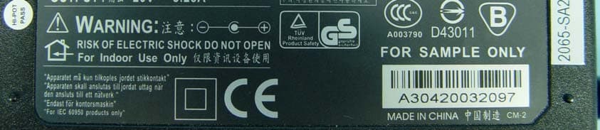
Click to zoom
Application Details
- Equipment Class
- DTS - Digital Transmission System
- Date of Grant
- Aug 22, 2004
- Application Purpose
- Original Equipment
- Date of Application
- Aug 22, 2004
- Equipment Note
- Notebook PC with Intel model WM3B2200BG WLAN card
- Frequency Range
- 2412.00000000 - 2462.00000000
- Company
- Uniwill Computer Corp.
- Country
- Taiwan
Documents & Files
Document Text
Text extracted from the exhibit documents filed with the FCC. Open a document above to read the original.
Users Manual
i -1 Notice The information in this user’s manual is subject to change without notice. THE MANUFACTURER OR RESELLER SHALL NOT BE LIABLE FOR ERRORS OR OMISSIONS CONTAINED IN THIS MANUAL AND SHALL NOT BE LIABLE FOR ANY CONSEQUENTIAL DAMAGES, WHICH MAY RESULT FROM THE PERFORMANCE OR USE OF THIS MANUAL. The information in this user’s manual is protected by copyright laws. No part of this manual may be photocopied or reproduced in any form without prior written authorization from the copyright owners. Copyright July, 2004 All rights reserved. Microsoft and Windows are registered trademarks of Microsoft Corporation. DOS, Windows 95/98/ME/2000/NT/XP are trademarks of Microsoft Corporation. Product names mentioned herein may be trademarks and/or registered trademarks of their respective owners/companies. The software described in this manual is delivered under a license agreement. The software may be used or copied only in accordance with the terms of the agreement. This product incorporates copyright protection technology that is protected by method claims of certain U.S. patents and other intellectual property rights owned by Macrovision Corporation and other rights owners. Use of this copyright protection technology must be authorized by Macrovision Corporation, and is intended for home and other limited viewing uses only unless otherwise authorized by Macrovision Corporation. Reverse engineering or disassembly is prohibited. Rev 1.0 i -2 TABLE OF CONTENTS PREFACE Symbols and Conventions Protecting Your Computer - Avoid Abusive Handling and Adverse Environment Chapter Summaries 1. GETTING TO KNOW THE BASICS Performance Features (1-2,3) System at a Glance (1-4) Front View (1-4,5,6,7) Rear View (1-8,9,10) Bottom View (1-11,12,13) AC Adapter (1-14) LED Status Indicators (1-15,16) Keyboard Features (1-17) Function (Quick) Keys (1-17) Windows Keys (1-18) Embedded Numeric Keypad (1-18) Touch Pad (1-19) Graphic Subsystem (1-20) Adjusting the Display Brightness (1-20) Extending the Life of the TFT Display Panel (1-20) Opening and Closing the Display Panel (1-21) Audio Subsystem (1-22) Adjusting the Volume in Windows (1-22) Voice Recording (1-22) Modem and Modem Setting (1-23) Ethernet Adapter (1-24) 2. BIOS SETUP AND SECURITY Entering the BIOS Setup Screen (2-3) Leaving the BIOS Setup Screen (2-3) BIOS Action Keys (2-3) Modifying the BIOS Settings (2-4) i -3 Main Setup (2-4) Advance Setup (2-4) Security Setup (2-5,6) Power Setup (2-6,7) Boot Setup (2-7,8) Exit Setup (2-8) 3. BATTERY POWER & POWER MANAGEMENT The Battery Pack (3-2) Lithium-Ion Battery Technology (3-2) Battery Low-Power Warning (3-3) Installing and Removing the Battery Pack (3-4,5) Charging the Battery and Charging Time (3-5) Checking the Battery Level (3-6) Prolonging the Battery’s Life and Usage Cycles (3-6) Using Windows Power Options (3-7) Windows’ Power Schemes (3-7,8) Suspend Modes (3-9,10) Power Button Action (3-11) Low Battery Warning (3-12) Power Manual Quick Access (3-13) 4. UPGRADING YOUR COMPUTER Upgrading the Hard Disk Drive (4-2,3,4,5) Upgrading the System Memory (4-6,7,8,9) 5. TROUBLE-SHOOTING First Step (5-2,3) Audio Problems (5-4) Hard Disk Problems (5-5,6) CD-ROM, DVD-ROM, CD-RW, or Combo Drive Problems (5-7) Display Problems (5-8) Keyboard and Mouse Problems (5-9) CMOS Battery Problems (5-10) Memory Problems (5-11) Modem Problems (5-12) Network Adapter / Ethernet Problems (5-13) i -4 PC Card / PCMCIA Problems (5-14) Performance Problems (5-15) Firewire (IEEE1394) and USB2.0 Problems (5-16) APPENDIX A Product Specification APPENDIX B Agency Regulatory Notices i -5 Preface Using This Manual This User’s Manual contains general information about the hardware and software setup, troubleshooting, and technical specifications of the notebook computer. Symbols and Conventions The following conventions and symbols are used in this manual: When keys are to be pressed at the same time, a plus (+) symbol is used. For instance, Fn+F7 means holding Fn and F7 keys at the same time. When a series of clicking actions is needed in Windows O/S, [ ] and > symbols are used. For instance, [Start > Settings > Control Panel > Display] means clicking the Start icon first, then the Settings, then the Control Panel, then the Display icon. When you need to make a selection with the touch pad (or mouse), you will be asked to ’select’ or ‘click’ or ‘double-click’, ‘right-click’ the item. Note: Text in this format and symbol means specific instructions, commentary, sidelights, or any additional information or notes that you should be aware of. Warning: Text in this format and symbol means that failures to comply with the given instructions or information could result in damage to your computer or could cause bodily harm or loss of life. i -6 Protecting Your Computer - Avoid Abusive Handling and Adverse Environment Follow the advice below will help ensure that you get the most out of your Investment. Your computer will serve you well if you take good care of it. Do not expose the computer to direct sunlight or place it near sources of heat. Do not subject it to temperatures below 0 o C (32 o F) or above 30 o C (86 o F). Do not expose the computer to magnetic fields. Do not expose the computer to moisture or rain. Do not spill water or liquid on the computer. Do not subject the computer to adverse shock and vibration. Do not expose the computer to dust and dirt. Do not place objects on top of the computer to avoid damaging the computer. Do not place the computer on rocky surfaces. Here are some ways of taking care of your AC adapter. Do not connect the adapter to any devices other than your computer. Do not let water get into the adapter. Do not block the ventilation airway of the adapter. Keep the adapter in a cool and ventilated place. Do not step on the power cord or place heavy objects on top of it. Carefully tuck away the power cord and any cables away from pedestrian traffic. When unplugging the power cord,…
Text truncated - open the document above for the full version.
Cover Letter(s)
FCC ID: SAZ-2200BG255 Report No.RF930715L14 Modular Approval Request Letter Advance Data Technology July 30, 2004 Dear Application Examiner, UNIWILL COMPUTER CORP.’s Notebook PC with FCC ID: SAZ-2200BG255, would like to have your authorization as a limited modular approval for the mini-pci card (Intel WM3B2200BG) specific to the Notebook PC which brand is Uniwill and the model is 255II1. The requirements of Public Notice DA00-1407 have been met and shown on the following statements. 1. “The modular transmitter must have its own RF shielding.”: The radio portion of this module has been shielded, please see exhibition External Photo. 2. “The modular transmitter must have buffered modulation/data inputs.” The EUT has buffered data inputs, it is integrated in chipArdon 2. 3. “The modular transmitter must have its own power supply regulation.” The chips IF converter and RF/IF converter which will influence the frequency radiation, have to be 2.9Vdc powered. The mini-pci interface provides 3.3VDC, so there are regulators in front of these chips, the part number of this regulator is LP3985. 4. “The modular transmitter must comply with the antenna requirements of section 15.203 and 15.204(C).” The EUT meets the FCC antenna requirements. The spurious emission, unique antenna connector and photo of antennas are shown in the test report. 5. “The modular transmitter must be tested in a stand-alone configuration” Due to the mini-pci card with brand Intel, and the model name WM3B2200BG is specified to the Laptop PC, the EUT is tested in full system configuration. Please see section Photographs of Test Configuration in the test report. 6. “The modular transmitter must be labeled with its own FCC ID number.” Please see exhibition Label Sample for the FCC ID of this module. And also in the exhibition Users Manual, there are instructions given to the OEM on how to label the end product. FCC ID: SAZ-2200BG255 Report No.RF930715L14 7. “The modular transmitter must comply with any specific rule or operating requirements applicable to the transmitter and the manufacturer must provide adequate instructions along with the module to explain any such requirements.” The EUT is compliant with all applicable FCC rules. Detail instructions for maintaining compliance are given in the Users Manual. 8. “The modular transmitter must comply with any applicable RF exposure requirements.” The EUT is compliant with all applicable RF exposure requirements. RF Exposure is addressed in the RF exposure exhibition. Please contact me if you have any further questions. Thanks for your attention. Best Regards, Ellis Wu / Manager Advance Data Technology
External Photos
Page 1 CONSTRUCTION PHOTOS OF EUT Page 2 Page 3 Page 4 Page 5 Page 6 Page 7 Page 8 Page 9 Page 10 Page 11 Page 12 Page 13 Page 14 Page 15 Page 16
ID Label/Location Info
FCC ID Label Location
ID Label/Location Info
2004/06/172004/07/07 2004/07/132004/08/05 R1*3 C4 84.10.15 + _ 5 0 . 1 0 . 1 5 + _ VENDOR CORD WLAN LABEL P/NO. UNIWILL 2004/07/27 R1*3 C4 84.10.15 + _ 5 0 . 1 0 . 1 5 + _ SIP Model No.255II3 255II3 63-UG5015-00 CM-2 63-UG5015-00 CM-2 SIP Model No.255II3 255II3 VENDOR CORD P/NO. UNIWILL WLAN LABEL SIP SIP Model No.255TI1 Model No.255TI1 255TI1 255TI1 VENDOR CORD P/NO. 63-UG5011-00 CM-2 63-UG5011-00 CM-2 2004/06/17 2004/07/07 WLAN LABEL UNIWILL SIP SIP Model No.255KI1 Model No.255KI1 255KI1 255KI1 VENDOR CORD P/NO. 63-UGXXXX-XX CM-2 63-UGXXXX-XX CM-2 2004/08/05 WLAN LABEL UNIWILL
Internal Photos
Page 17 Page 18 Page 19 Page 20 Page 21 Page 22 Page 23 Page 24 Page 25 Page 26 Page 27 Page 28 Page 29
Operational Description
FCC ID: SAZ-2200BG255 Report No.RF930715L14 Operational Description This device is a Notebook PC (with wireless card:Intel WM3B2200BG), which operates in the 2.4GHz frequency spectrum with throughput of up to 54Mbps which OFDM technique will be applied. If the signal to noise radio is too poor which could not support 54Mbps, the 11Mbps data rate with CCK technique will be applied. The transmitter of the EUT is powered by AC Adapter. Both antennas are PIFA antenna with UFL antenna connector. The other instruction, please have a look at the users manual.
RF Exposure Info
FCC ID: SAZ-2200BG255 Report No.: SA930715L141Issued: July 31, 2004 SAR TEST REPORT REPORT NO.: SA930715L14 MODEL NO.: 255xIy (with wireless card: Intel WM3B2200BG) RECEIVED: July 15, 2004 TESTED: July 28, 2004 APPLICANT: UNIWILL COMPUTER CORP. ADDRESS: 5F, No.9, Wu Chiuan Rd, Wu Gu Ind.Park, Taipei, Taiwan, R. O. C. ISSUED BY: Advance Data Technology Corporation LAB LOCATION: No. 19, Hwa Ya 2nd rd., Kueishan, Taoyuan, Taiwan, R.O.C. This test report consists of 34 pages in total except Appendix. It may be duplicated completely for legal use with the approval of the applicant. It should not be reproduced except in full, without the written approval of our laboratory. The client should not use it to claim product endorsement by CNLA or any government agencies. The test results in the report only apply to the tested sample. 0528 ILAC MRA FCC ID: SAZ-2200BG255 Report No.: SA930715L142Issued: July 31, 2004 Table of Contents 1.CERTIFICATION................................................................................................................3 2.GENERAL INFORMATION...............................................................................................4 2.1GENERAL DESCRIPTION OF EUT................................................................................4 2.2GENERAL DESCRIPTION OF APPLIED STANDARDS................................................6 2.3GENERAL INOFRMATION OF THE SAR SYSTEM.......................................................6 2.4GENERAL DESCRIPTION OF THE SPATIAL PEAK SAR EVALUATION .................10 3.DESCRIPTION OF TEST MODES AND CONFIGURATIONS....................................14 4.DESCRIPTION OF SUPPORT UNITS..........................................................................15 5.TEST RESULTS...............................................................................................................16 5.1TEST PROCEDURES.....................................................................................................16 5.2MEASURED SAR RESULT............................................................................................17 5.3SAR LIMITS......................................................................................................................19 5.4RECIPES FOR TISSUE SIMULATING LIQUIDS..........................................................21 5.5TEST EQUIPMENT FOR TISSUE PROPERTY............................................................23 6.SYSTEM VALIDATION....................................................................................................24 6.1TEST EQUIPMENT.........................................................................................................24 6.2TEST PROCEDURE.......................................................................................................24 6.3VALIDATION RESULT....................................................................................................26 6.4SYSTEM VALIDATION UNCERTAINTIES....................................................................27 7.MEASUREMENT SAR PROCEDURE UNCERTAINTIES...........................................28 7.1PROBE CALIBRATION UNCERTAINTY.......................................................................28 7.2ISOTROPY UNCERTAINTY...........................................................................................28 7.3BOUNDARY EFFECT UNCERTAINTY..........................................................................29 7.4PROBE LINEARITY UNCERTAINTY.............................................................................29 7.5READOUT ELECTRONICS UNCERTAINTY................................................................29 7.6RESPONSE TIME UNCERTAINTY................................................................................30 7.7INTEGRATION TIME UNCERTAINTY...........................................................................31 7.8PROBE POSITIONER MECHANICAL TOLERANCE..................................................31 7.9PROBE POSITIONING...................................................................................................32 7.10PHANTOM UNCERTAINTY............................................................................................32 7.11DASY4 UNCERTAINTY BUDGET.................................................................................33 8.INFORMATION ON THE TESTING LABORATORIES.................................................34 APPENDIX A: TEST CONFIGURATIONS AND TEST DATA APPENDIX B: ADT SAR MEASUREMENT SYSTEM APPENDIX C: PHOTOGRAPHS OF SYSTEM VALIDATION APPENDIX D: SYSTEM CERTIFICATE & CALIBRATION FCC ID: SAZ-2200BG255 Report No.: SA930715L143Issued: July 31, 2004 1. CERTIFICATION PRODUCT : Notebook PC (with wireless card:Intel WM3B2200BG) MODEL NO. : 255xIy (with wireless card: Intel WM3B2200BG) (“x” may be as I or T to denote different CPU type, “y” may be as 0 ~ 9 or blank to denote different color of enclosure) BRAND NAME : Uniwill (refer to page5 for other brand name) TESTED : July 28, 2004 APPLICANT : UNIWILL COMPUTER CORP. TEST ITEM : ENGINEERING SAMPLE STANDARDS :FCC Part 2 (Section 2.1093), FCC OET Bulletin 65, Supplement C (01-01), RSS-102 The above equipment has been tested by Advance Data Technology Corporation, and found compliance with the requirement of the above standards. The test record, data evaluation & Equipment Under Test (EUT) configurations represented herein are true and accurate accounts of the measurements of the sample’s EMC characteristics under the conditions specified in this report. PREPARED BY:, DATE:July 31, 2004 ( Windy Chou ) TECHNICAL ACCEPTANCE:, DATE:July 31, 2004 Responsible for RF ( Gary Chang ) APPROVED BY:, DATE:July 31, 2004 ( Cody Chang, Supervisor ) FCC ID: SAZ-2200BG255 Report No.: SA930715L144Issued: July 31, 2004 2. GENERAL INFORMATION 2.1 GENERAL DESCRIPTION OF EUT PRODUCT Notebook PC (with wireless card:Intel WM3B2200BG) MODEL NO. 255xIy (with wireless card: Intel WM3B2200BG) POWER SUPPLY 18.5Vdc powered by …
Text truncated - open the document above for the full version.
RF Exposure Info
APPENDIX B: ADT SAR MEASUREMENT SYSTEM APPENDIX C: PHOTOGRAPHS OF SYSTEM VALIDATION APPENDIX D: SYSTEM CERTIFICATE & CALIBRATION D1: SAM PHANTOM D2: DOSIMETRIC E-FIELD PROBE
RF Exposure Info
D3:DAE
RF Exposure Info
D4: SYSTEM VALIDATION DIPOLE
Test Report
FCC ID: SAZ-2200BG255 Report No.: RF930715L141Issued: July 27, 2004 FCC TEST REPORT REPORT NO.: RF930715L14 MODEL NO.: 255xIy (with wireless card: Intel WM3B2200BG) RECEIVED: July 15, 2004 TESTED: July 23 ~ July 28, 2004 APPLICANT: UNIWILL COMPUTER CORP. ADDRESS: 5F, No. 9, Wu Chiuan Rd., Wu Gu Ind. Park, Taipei, Taiwan, R.O.C. ISSUED BY: Advance Data Technology Corporation LAB LOCATION: No. 19, Hwa Ya 2nd Rd., Kueishan, Taoyuan, Taiwan, R.O.C. This test report consists of 74 pages in total. It may be duplicated completely for legal use with the approval of the applicant. It should not be reproduced except in full, without the written approval of our laboratory. The client should not use it to claim product endorsement by CNLA, or any government agencies. The test results in the report only apply to the tested sample. 0528 ILAC MRA FCC ID: SAZ-2200BG255 Report No.: RF930715L142Issued: July 27, 2004 Table of Contents 1CERTIFICATION ........................................................................................... 4 2SUMMARY OF TEST RESULTS................................................................... 5 2.1GENERAL DESCRIPTION OF EUT.............................................................. 5 3GENERAL INFORMATION ........................................................................... 6 3.1GENERAL DESCRIPTION OF EUT.............................................................. 6 3.2DESCRIPTION OF TEST MODES................................................................ 7 3.3GENERAL DESCRIPTION OF APPLIED STANDARDS............................... 7 3.4DESCRIPTION OF SUPPORT UNITS .......................................................... 8 3.5CONFIGURATION OF SYSTEM UNDER TEST........................................... 8 4TEST TYPES AND RESULTS....................................................................... 9 4.1CONDUCTED EMISSION MEASUREMENT ................................................ 9 4.1.1LIMITS OF CONDUCTED EMISSION MEASUREMENT.............................. 9 4.1.2TEST INSTRUMENTS .................................................................................. 9 4.1.3TEST PROCEDURES................................................................................. 10 4.1.4DEVIATION FROM TEST STANDARD ....................................................... 10 4.1.5TEST SETUP ...............................................................................................11 4.1.6EUT OPERATING CONDITIONS.................................................................11 4.1.7TEST RESULTS.......................................................................................... 12 4.2RADIATED EMISSION MEASUREMENT ................................................... 18 4.2.1LIMITS OF RADIATED EMISSION MEASUREMENT................................. 18 4.2.2TEST INSTRUMENTS ................................................................................ 19 4.2.3TEST PROCEDURES................................................................................. 20 4.2.4DEVIATION FROM TEST STANDARD ....................................................... 20 4.2.5TEST SETUP .............................................................................................. 21 4.2.6EUT OPERATING CONDITIONS................................................................ 21 4.2.7TEST RESULTS.......................................................................................... 22 4.36dB BANDWIDTH MEASUREMENT .......................................................... 36 4.3.1LIMITS OF 6dB BANDWIDTH MEASUREMENT ........................................ 36 4.3.2TEST INSTRUMENTS ................................................................................ 36 4.3.3TEST PROCEDURE ................................................................................... 37 4.3.4DEVIATION FROM TEST STANDARD ....................................................... 37 4.3.5TEST SETUP .............................................................................................. 37 4.3.6EUT OPERATING CONDITIONS................................................................ 37 4.3.7TEST RESULTS.......................................................................................... 38 4.4MAXIMUM PEAK OUTPUT POWER .......................................................... 46 FCC ID: SAZ-2200BG255 Report No.: RF930715L143Issued: July 27, 2004 4.4.1LIMITS OF MAXIMUM PEAK OUTPUT POWER MEASUREMENT ........... 46 4.4.2TEST INSTRUMENTS ................................................................................ 46 4.4.3TEST PROCEDURES................................................................................. 47 4.4.4DEVIATION FROM TEST STANDARD ....................................................... 47 4.4.5TEST SETUP .............................................................................................. 47 4.4.6EUT OPERATING CONDITIONS................................................................ 47 4.4.7TEST RESULTS.......................................................................................... 48 4.5POWER SPECTRAL DENSITY MEASUREMENT...................................... 49 4.5.1LIMITS OF POWER SPECTRAL DENSITY MEASUREMENT ................... 49 4.5.2TEST INSTRUMENTS ................................................................................ 49 4.5.3TEST PROCEDURE ................................................................................... 50 4.5.4DEVIATION FROM TEST STANDARD ....................................................... 50 4.5.5TEST SETUP .............................................................................................. 50 4.5.6EUT OPERATING CONDITIONS................................................................ 50 4.5.7TEST RESULTS.......................................................................................... 51 4.6BAND EDGES MEASUREMENT ................................................................ 59 4.6.1LIMITS OF BAND…
Text truncated - open the document above for the full version.
Test Setup Photos
FCC ID: SAZ-2200BG255 Report No.: RF930715L1470Issued: July 27, 2004 5 PHOTOGRAPHS OF THE TEST CONFIGURATION CONDUCTED EMISSION TEST FCC ID: SAZ-2200BG255 Report No.: RF930715L1471Issued: July 27, 2004 FCC ID: SAZ-2200BG255 Report No.: RF930715L1472Issued: July 27, 2004 RADIATED EMISSION TEST FCC ID: SAZ-2200BG255 Report No.: RF930715L1473Issued: July 27, 2004
Contact Information
Applicant
Albert Chen(VP/R&D Division)
Technical Contact
Advance Data Technology CorporationEllis Wu
[email protected]+886 3 318 3232
No. 19 Hwa Ya 2nd Rd · Kueishan Taoyuan · Taiwan
Test Firm
Bureau Veritas CPS (H.K.) Ltd. Taoyuan BranchRichard Chen
Technical Specifications
| # | Rule Parts | Frequency Range | Power Output |
|---|---|---|---|
| 1 | 15C | 2.41 GHz - 2.46 GHz | 63.00 mW |
Other Applications from Uniwill Computer Corp.
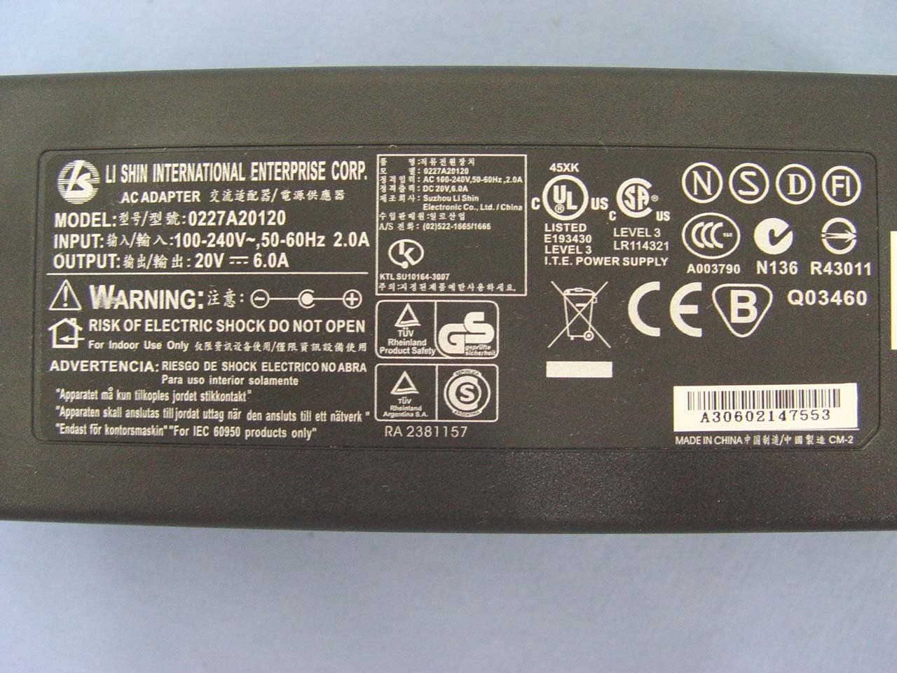
SAZ-3945ABGXPCIA
May 25, 2006Shuttle XPC (Wireless 802.11a+b+g)
Equipment Class
NII - Unlicensed National Information Infrastructure TX
SAZ-GUBTCRQ2426
May 10, 2006Notebook PC
Equipment Class
PCB - PCS Licensed Transmitter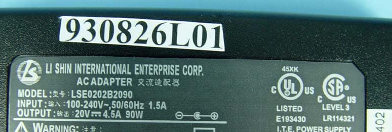
SAZ-MS6833
Oct 15, 2004Wireless mini-PCI Card Model MS-6833
Equipment Class
DTS - Digital Transmission System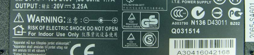
SAZ-2200BG223
Jul 15, 2004Notebook PC with Wireless LAN Mini-PCI Card
Equipment Class
DTS - Digital Transmission System