SBIRVR-6600Wireless Gamepad
Shenzhen Litestar Electronics Technology Co., Ltd.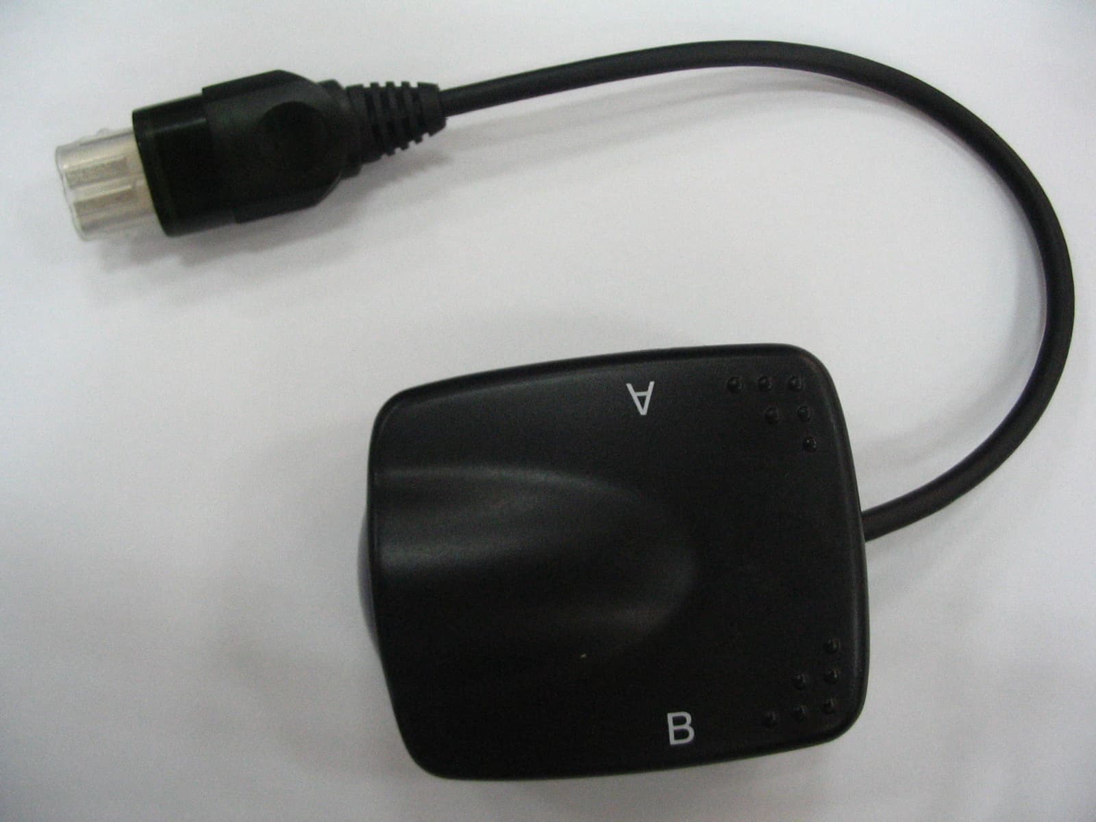
Click to zoom
Application Details
- Equipment Class
- DSS - Part 15 Spread Spectrum Transmitter
- Date of Grant
- Jul 21, 2004
- Application Purpose
- Original Equipment
- Date of Application
- Jul 21, 2004
- Equipment Note
- Wireless Gamepad
- Frequency Range
- 2402.00000000 - 2481.00000000
- Country
- China
Documents & Files
Document Text
Text extracted from the exhibit documents filed with the FCC. Open a document above to read the original.
Users Manual
Operation Manual of XBox 2.4GHz RF Game Controller Brief Introduction Thank you for purchasing our XBox 2.4GHz Radio Frequency Game Controller. Along with our highest manufacturing standards and testing throughout its development, we ensure you could get the best possible product. To make it fully fits your X-Box Console, please review this user’s instruction manual carefully for operation. Characteristic 1, Applicable for X-Box Console and various of software the console supported; 2, Support Dual Shock game software; 3, Two Built-in motors make the game more realistic; 4, Special device of low power consumption feature; 5, Macro function and LED indicator; 6, Alarm function for lower voltage; 7, FC function (Short for “Force Connection”) between the appointed controller and the appointed receiver; 8, Extra connection cable for use instead of batteries; 9, ISM frequency range between 2.4GHz – 2.5GHz 10, Available over 10 meter straightaway range; 11, Available 20 RF controllers playing at the same time within valid range; 12, Normal voltage: 4V – 7V (4 X AA batteries) Keystroke Layout Connection and Installation 1, Insert the receiver to the socket of X-Box Console and turn on the power. 2, Place the 4 X AA batteries inside the controller first, and move the switch to the position of “ON”, then press “Start” “Left Thumb” “Right Thumb” or “FC”so as to activate the controller. The Led Indicator on the receiver will be on; 3, You can play by pressing 8-way Directional button and other control buttons. Operation of the Function 1, Low Power Consumption To save the power consumption, there is a special “sleeping mode” built into this controller. The general conditions are as follows: a, Under the power-on condition for controller, no receiver is found over 15 seconds; b, Under the disconnection condition, the receiver can’t be re-connected with the controller over 6 seconds; c, Under the power-on condition, no any operation acts on any button or axes over 3 minutes; d, When pressing down the FC group button “Back + Right Thumb” on the controller, but the “FC” button on the receiver isn’t pressed down over 15 seconds; e, Under the sleeping mode, you can press “Start”,“Left Thumb” or “Right Thumb” so as to activate the controller. 2, Definition of Turbo function a, The buttons “A, B, X, Y, Left Trigger, Right Trigger, White Key, Black Key” can be defined with Turbo function. b, Press “Turbo + any action button” at the same time for odd times, the button will be with Turbo function. Press “Turbo + the defined action button” at the same time for even times, the defined Turbo function will vanish. 3, Vibration function While playing, press “Back + Right Thumb” group button at the same time, the motor vibrates once, which shows the vibration function exits. Press “Back + Right Thumb” group button for the 2 nd time, the motor vibrates twice, which shows the vibration function is activated again. 4, Alarm function for lower voltage When the voltage of the batteries is too low, Macro-Led will keep on flashing, which shows that the new batteries should be provided, or the original batteries should be recharged. Also the vibration function is shut off automatically. 5, FC function (short for “Force Connection”) between the appointed controller and the appointed receiver You can appoint the RF controller with the appointed receiver when more RF controllers work in the same operating circumstance. The method is to press down the FC group button “Select + Left Thumb” on the controller (or the button “FC” on the receiver), then press the button “FC” on the appointed receiver (or the FC group button “Select + Left Thumb” on the controller) within 15 seconds. 6, Macro function (with memory after power off suddenly) Only “White Key, Black Key, Left Thumb and Right Thumb” buttons can be defined with Macro function. After definition with Macro function, its original function vanishes. In addition, the Macro function can be one or more group functions among buttons “A, B, X, Y, White Key, Black Key, Left Trigger, Right Trigger, D-PAD”. The “Back” button represents as Space button for use. A, The definition of Macro function: a, Press “Macro” button, the Led is on. b, Press any defined button among “White Key, Black Key, Left Thumb, Right Thumb”, such as “White Key”; c, Press a few function buttons and group them as defined functions, such as “A, X, Y, Left Trigger” buttons. (Remember that each button can be defined with group function of no more than 15 steps. For examples, pressing “A” once, or pressing “B, X, Left Trigger” buttons at the same time means 1 step. It will be saved automatically and exit after 15 steps. ) d, Press “Macro” key and exit. The Led indicator is off. Thus, “White Key” has the function of “A-X-Y-Left Trigger” group buttons. B, The cancellation of “Macro” function a, Press “Macro” button, the Led indicator is on. b, Press any defined button, such as “White Key”, the Led indicator flashes. c, Press “Macro” button, the Led indicator is off. The defined “Macro” function on “White Key” button vanishes. 7, While not using the batteries, you can use the extra connection cable for playing. Connect the cable between the port of console and the socket marked “DC5V” on the controller first, and the Green Led is on. Then turn on the power, and start to play. Battery Safety z Batteries are to be inserted with the correct polarity z Use only the recommended batteries z Do not mix old & new batteries z Do not mix Alkaline, Standard(Carbon Zinc) or rechargeable (Nickel-Cadmium) batteries z Dispose of batteries safety & correctly z Do not dispose of batteries in fire, batteries may explode or leak z Remove batteries if the toy will not be used for a long period of time z Exhausted batteries are to be removed from the toy z The supply terminals are not to be short-circuited z Non-rechargeable batteries are not to be recharged NOTE: THE MANUFACTURER IS NOT RESPONSIBLE FOR ANY RADIO OR TV INTERFERENCE CAUSE…
Text truncated - open the document above for the full version.
ID Label/Location Info
FCC ID Location FCC ID Label Sample F C C I D : SBIRVR-6600 This device complies with Part 15 of the FCC Rules. Operation is subject to the following two conditions: (1) this device may not cause harmful interference, and (2) this device must accept any interference received, including interference that may cause undesired operation.
Operational Description
2.4GHz RF X-BOX Wireless Controller Host Working Principle 1. It is a 2.4G RF product. It works at the frequency of ISM Band (2.4GHZ). There are up to 80 channels, and the frequency interval between each channel is 1M Hz. 2. Evenly Randomized Frequency Hopping Sequence method is implemented in the RF technology. 3. It works in “Master” Mode. We call it “Host.” The working procedures are: a) When power on, the Host will do the frequency hopping according to a certain sequence, and then send the connection command. b) If there is a Device response, the Host will judge whether it can be permitted to connect. c) If it can be permitted to connect, then send the connection command to build up the connection. d) The Host sends the request command to the Device to get the Axes and Buttons value. e) The Device sends the Axes and Buttons value to the Host. f) The Host will identify the data received and then do the data detection and data correction. g) The Host will save the data received if there is no error. h) The Host judges whether it is required to send Axes and Buttons value to PS2 console. i) If it is required, then send the saved data to PS2 console. j) The Host judges whether there is any Motor command and/or Motor value sent from PS2 console. k) If there is, then the Host will save the received Motor data. l) The Host send Motor commands to the Device, and send the Motor value to the Device. m) Repeat Step e) to Step l)
Test Report
Report No.:GLEM0040600184RF-1 Page: 1 of 36 FCC ID: SBIRVR-6600 Authorized Signature: Kent Hsu Laboratory Manager SGS-CSTC Co.,Ltd. This report refers to the General Conditions for Inspection and Testing Services, printed overleaf This report details the results of the testing carried out on one sample. The results contained in this test report do not relate to other samples of the same product and does not permit the use of the SGS PRODUCT CERTIFICATION MARK.. The manufacturer should ensure that all products in series production are in conformity with the product sample detailed in this report. This report may only be reproduced and distributed in full. If the product in this report is used in any configuration other than that detailed in the report, the manufacturer must ensure the new system complies with all relevant standards. Any mention of SGS International Electrical Approvals or testing done by SGS International Electrical Approvals in connection with, distribution or use of the product described in this report must be approved by SGS International Electrical Approvals in writing. Member of the SGS Group (Société Générale de Surveillance) SGS-CSTC Standards Technical Services Ltd. 1/F., Building No. 1 Building, Agriculture Machinery Materials Co. Wushan Road, Shipai, Tianhe District,Guangzhou, China Telephone: +86 (0) 20 3848 1001 Fax: +86 (0) 20 3848 1006 [email protected] FEDERAL COMMUNICATIONS COMMISSION Registration number: 282399 FCC TEST REPORT Application No. : GLEM0040600184 Applicant: Shenzhen Litestar Electronics Technology Co., Ltd FCC ID: SBIRVR-6600 Fundamental Carrier Frequency : 2.402GHz to 2.481GHz Equipment Under Test (EUT): Name: Wireless Gamepad Model: XB-6600 Standards: FCC PART 15, SUBPART C : 2003 ( Section 15.247) Date of Receipt: 11 June 2004 Date of Test: 15 June to 16 July 2004 Date of Issue: 19 July 2004 Test Result : PASS * * In the configuration tested, the EUT complied with the standards specified above. SGS-CSTC Standards Technical Services Ltd. Report No.:04.03.0653EF-1 Page: 2 of 36 FCC ID: SBIRVR-6600 2 Test Summary Test Test Requirement Stanadard Paragraph Result Conducted Emission (150KHz to 30MHz) FCC PART 15 :2003 Section 15.209 PASS Radiated Emission (30MHz to 25GHz) FCC PART 15 :2003 Section 15.207 PASS Maximum Peak Output Power FCC PART 15 :2003 Section 15.247 (b1) PASS Hopping Channel Number FCC PART 15 :2003 Section 15.247 (b1) PASS Occupied Bandwidth FCC PART 15 :2003 Section 15.247 (a1) PASS Carrier Frequencies Separated FCC PART 15 :2003 Section 15.247 (a1,iii) PASS Band Edges Measurement FCC PART 15 :2003 Section 15.247 (c) PASS Dell Time FCC PART 15 :2003 Section 15.247 (c) PASS Power Spectral Density Measurement FCC PART 15 :2003 Section 15.247 (d) PASS SGS-CSTC Standards Technical Services Ltd. Report No.:04.03.0653EF-1 Page: 3 of 36 FCC ID: SBIRVR-6600 3 Contents Page 1 COVER PAGE.........................................................................................................................................................1 2 TEST SUMMARY.................................................................................................................................................... 2 3 CONTENTS .............................................................................................................................................................. 3 4 GENERAL INFORMATION.................................................................................................................................. 4 4.1 CLIENT INFORMATION....................................................................................................................................... 4 4.2 GENERAL DESCRIPTION OF E.U.T...................................................................................................................... 4 4.3 DESCRIPTION OF SUPPORT UNITS....................................................................................................................... 4 4.4 STANDARDS APPLICABLE FOR TESTING............................................................................................................. 4 4.5 TEST LOCATION................................................................................................................................................. 4 4.6 OTHER INFORMATION REQUESTED BY THE CUSTOMER...................................................................................... 4 4.7 TEST FACILITY................................................................................................................................................... 5 5 TEST RESULTS....................................................................................................................................................... 6 5.1 TEST INSTRUMENTS........................................................................................................................................... 6 5.2 E.U.T. OPERATION............................................................................................................................................ 6 5.3 TEST RESULT..................................................................................................................................................... 7 5.3.1 Conducted Emissions Mains Terminals, 150kHz to 30MHz ........................................................................ 7 5.3.2 Radiated Emissions ...................................................................................................................................... 8 5.3.3 Maximum Peak Output Power............................................................................................................... 15 5.3.4 Hopping Channel Number..................................................................................................................... 17 5.3.5 Occupied Bandwidth & Carrier Frequencies Separated................................................................... 18 5.3…
Text truncated - open the document above for the full version.
Contact Information
Applicant
Amy Lee(Sales Manager)
Test Firm
SGS-CSTC Standards Technical Services Co., LtdJerry Chan
Technical Specifications
| # | Rule Parts | Frequency Range | Power Output |
|---|---|---|---|
| 1 | 15C | 2.40 GHz - 2.48 GHz | 54.00 µW |
Other Applications from Shenzhen Litestar Electronics Technology Co., Ltd.
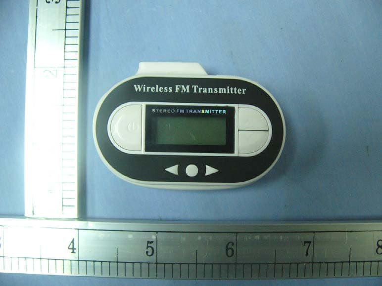
SBILSIP163K
Jan 20, 2008fm transmitter with LCD
Equipment Class
DXX - Part 15 Low Power Communication Device Transmitter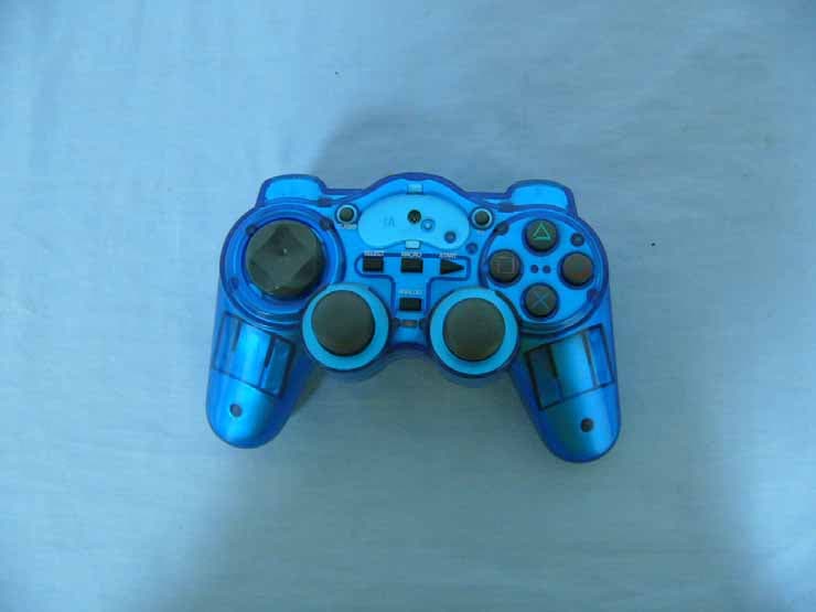
SBIPS2-7002
Nov 14, 2005PS2 Wireless Controller
Equipment Class
DXX - Part 15 Low Power Communication Device Transmitter
SBIPS2-7002R
Nov 14, 2005PS2 Wireless Controller
Equipment Class
DXX - Part 15 Low Power Communication Device Transmitter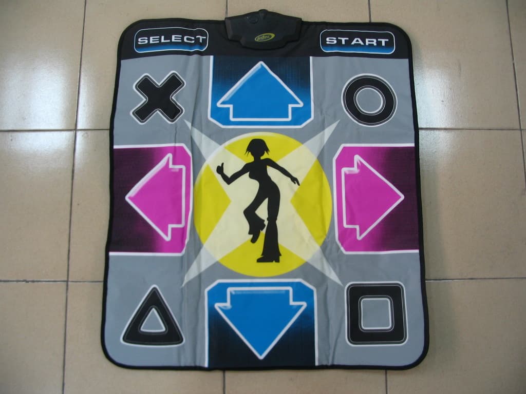
SBIDCM-0012
Aug 02, 2004Wireless Dance Mat
Equipment Class
DSS - Part 15 Spread Spectrum Transmitter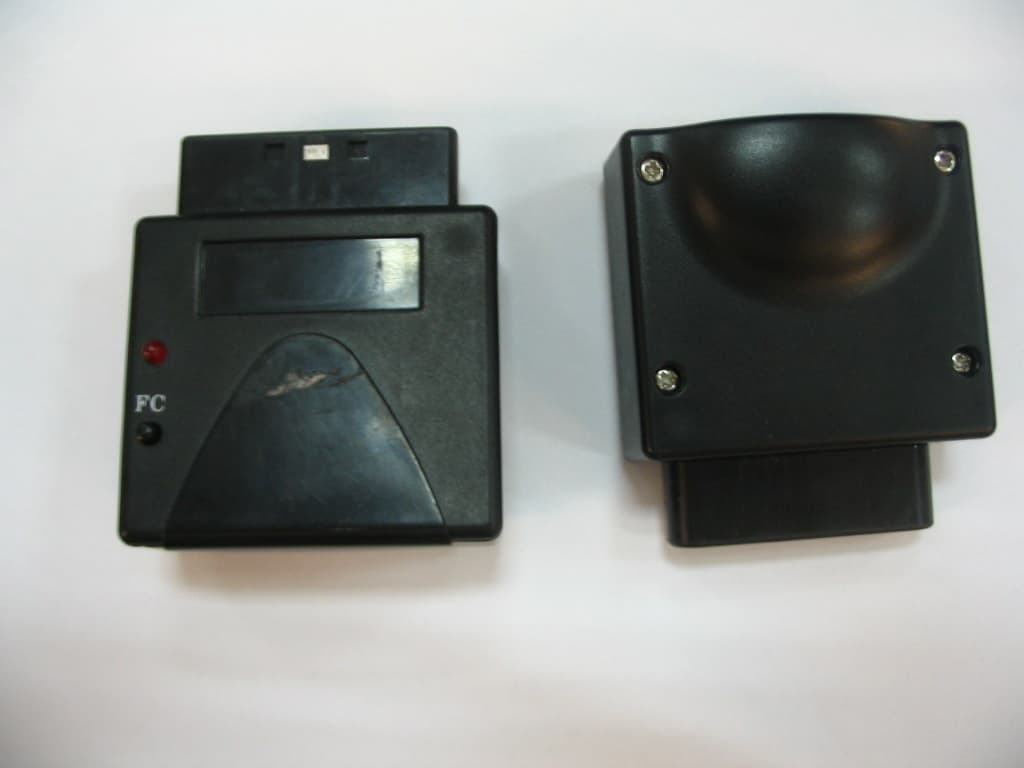
SBIRVR-0012
Aug 01, 2004Wireless Dance Mat
Equipment Class
DSS - Part 15 Spread Spectrum Transmitter