SDBAMDS1000TRFixed Microwave Services
Sensus Metering Systems Inc.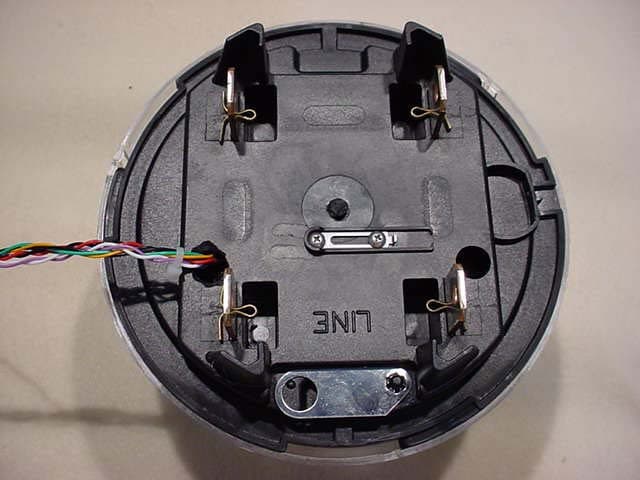
Click to zoom
Application Details
- Equipment Class
- PCB - PCS Licensed Transmitter
- Date of Grant
- Aug 24, 2004
- Application Purpose
- Original Equipment
- Date of Application
- Aug 24, 2004
- Equipment Note
- Fixed Microwave Services
- Frequency Range
- 932.23125000 - 941.23125000
- Company
- Sensus Metering Systems Inc.
- Country
- United States
Documents & Files
Document Text
Text extracted from the exhibit documents filed with the FCC. Open a document above to read the original.
Users Manual
Model: AMDS-1000TR Advanced Compliance Solutions FCCID: SDBAMDS1000TR Narrowband PCS Transmitter Certification Test Report Model: AMDS-1000TR FCC ID: SDBAMDS1000TR ACS Report Number: 04-0166-24D Installation / User’s Guide AMDS iCon AMR Electric Meter Installation Guidelines Draft Copy INTRODUCTION: The following document briefly describes the installation of an AMDS iCon Transceiver equipped power meter. The scope of the document is to describe how to program the meter after proper installation by trained utility company technicians or licensed electricians. THIS METER IS ONLY TO BE INSTALLED BY QUALIFIED PERSONNEL! PROCEDURE: Confirm that the meter has been installed by a qualified entity or individual. Turn on the hand-held meter-programming device. (Either the Palm “Zire” or customized programming device supplied by utility). Select “Program Electric Meter” when prompted by the meter-programming device. Using the wand attached to the meter-programming device, read the bar code on the front of the power meter (see figure 1 for location). Pass the wand from left to right over the bar code. A successful read will result in a short beep sound being generated from the meter-programming device. After a successful bar code read (i.e. the meter-programming device beeped) the meter-programming device will prompt the operator to “program device with magnetic loop”. The magnetic loop is in the wand attached to the meter- programming device also. Looking directly at the meter, and mentally superimposing the hands of a clock on the meter face for reference, place the meter-programming wand at the 3:00 position of the meter face, on the side of the plastic meter cover, touching the plastic meter cover with the wand. (See photograph below). Select “Program” on the meter-programming device display. The meter- programming device will again beep when the meter has been programmed. Contact your supervisor for confirmation of meter operation. FCC INFORMATION: NOTE: This equipment has been tested and found to comply with the limits for a Class B digital device, pursuant to Part 15 of the FCC rules. These limits are designed to provide reasonable protection against harmful interference in a residential installation. This equipment generates, uses, and can radiate radio frequency energy and, if not installed and used in accordance with the instructions, may cause harmful interference to radio communications. However, there is no guarantee that interference will not occur in a particular installation. If this equipment does cause harmful interference to radio or television reception, which can be determined by turning the equipment off and on, the user is encouraged to try to correct the interference by one or more of the following measures: • Reorient of relocate the receiving antenna. • Increase the separation between the equipment and receiver. • Connect the equipment into an outlet or circuit different from that to which the receiver is connected. • Consult the dealer or an experienced radio/TV technician for help. WARNING: Changes or modifications to this device not expressly approved by AMDS LLC could void the user’s authority to operate this equipment. Photograph showing bar code position and 3:00 position for programming wand placement on meter.
External Photos
Model: AMDS-1000TR Advanced Compliance Solutions FCCID: SDBAMDS1000TR Narrowband PCS Transmitter Certification Test Report Model: AMDS-1000TR FCC ID: SDBAMDS1000TR ACS Report Number: 04-0166-24D External Photographs Model: AMDS-1000TR Advanced Compliance Solutions FCCID: SDBAMDS1000TR Figure 1: External Front Model: AMDS-1000TR Advanced Compliance Solutions FCCID: SDBAMDS1000TR Figure 2: External Rear
ID Label/Location Info
Model: AMDS-1000TR Advanced Compliance Solutions FCCID: SDBAMDS1000TR Narrowband PCS Transmitter Certification Test Report Model: AMDS-1000TR FCC ID: SDBAMDS1000TR ACS Report Number: 04-0166-24D Product Labeling Model: AMDS-1000TR Advanced Compliance Solutions FCCID: SDBAMDS1000TR FCC LABEL: FCC ID: SDBAMDS1000TR THIS DEVICE COMPLIES WITH PART 15 OF THE FCC RULES. OPERATION IS SUBJECT TO THE FOLLOWING TWO CONDITIONS: (1) THIS DEVICE MAY NOT CAUSE HARMFUL INTERFERENCE, AND (2) THIS DEVICE MUST ACCEPT ANY INTERFERENCE RECEIVED, INCLUDING INTERFERENCE THAT MAY CAUSE UNDESIRED OPERATION. Figure 1: FCC Label Placement Model: AMDS-1000TR Advanced Compliance Solutions FCCID: SDBAMDS1000TR Figure 2: FCC Label Placement
Internal Photos
Model: AMDS-1000TR Advanced Compliance Solutions FCCID: SDBAMDS1000TR Narrowband PCS Transmitter Certification Test Report Model: AMDS-1000TR FCC ID: SDBAMDS1000TR ACS Report Number: 04-0166-24D Internal Photographs Model: AMDS-1000TR Advanced Compliance Solutions FCCID: SDBAMDS1000TR Figure 1. Power Supply Board Front Figure 2. Power Supply Board Rear Model: AMDS-1000TR Advanced Compliance Solutions FCCID: SDBAMDS1000TR Figure 3. RF Board Front Figure 4. RF Board Rear
RF Exposure Info
Model: AMDS-1000TR Advanced Compliance Solutions FCCID: SDBAMDS1000TR Narrowband PCS Transmitter Certification Test Report Model: AMDS-1000TR FCC ID: SDBAMDS1000TR ACS Report Number: 04-0166-24D RF Exposure Model: AMDS-1000TR Advanced Compliance Solutions FCCID: SDBAMDS1000TR General Information: Applicant: AMDS LLC ACS Project: 04-0166 FCC ID: SDBAMDS1000TR Device Category: Mobile Environment: Uncontrolled/General Poplation Technical Information: Antenna Type: PCB Antenna Gain: 0dBi Transmitter Conducted Power: 30.4 Maximum System EIRP: 30.4 Operating Configuration: Fixed Mounted to a Wall Exposure Conditions: Greater than 20cm MPE Calculation The minimum separation distance is calculated as follows: E(V/m) = xPxG30 Power Density: P d =(mW/cm 2 ) = d MPE Distance MPE Calculator for Mobile Equipment Limits for General Population/Uncontrolled Exposure* Transmit Freq. (MHz) Radio Power (dBm) Power Density Limit (mW/Cm2) Radio Power (W) Antenna Gain (dBi) Antenna Gain (mW eq.) E (V/m) MPE Distance (cm) 940.1125 30.5 0.63 1.12202 0 1.00 48.73 11.9047 901.1125 30.5 0.60 1.12202 0 1.00 47.56 12.1987 932.23125 30.5 0.62 1.12202 0 1.00 48.35 12.0004 941.23125 30.5 0.63 1.12202 0 1.00 48.73 11.9047 Installation Guidelines The installation manual contains the following text advising how to install the equipment to maintain compliance with the FCC RF exposure requirements: “RF Exposure (Intentional Radiators Only) In accordance with FCC requirements of human exposure to radiofrequency fields, the radiating element shall be installed such that a minimum separation distance of (20cm) is maintained between the radiating element and the user and/or general population.” Conclusion This device complies with the MPE requirements by providing adequate separation between the device, any radiating structure and the general population. E 2 3770
Test Report
5015 B.U. Bowman Drive Buford, GA 30518 USA Voice: 770-831-8048 Fax: 770-831-8598 FCC Part 24 Transmitter Certification Test Report FCC ID: SDBAMDS1000TR FCC Rule Part: CFR 47 Part 24 Subpart D ACS Report Number: 04-0166-24D Manufacturer: AMDS. Equipment Type: Electricity Meter Transmitter Model: AMDS-1000TR Test Begin Date: June 1, 2004 Test End Date: August 11, 2004 Report Issue Date: August 13, 2004 FOR THE SCOPE OF ACCREDITATION UNDER LAB Code 200612 Reviewed by: Prepared by: Rich Bianco Lead EMC Approvals Engineer ACS, Inc. R. Sam Wismer Engineering Manager ACS, Inc. This test report shall not be reproduced except in full. This report may be reproduced in part with prior written consent of ACS, Inc. The results contained in this report are representative of the sample(s) submitted for evaluation. This report contains 30 pages ACS Report: 04-0166-24D Advanced Compliance Solutions Page 2 Table of Contents 1.0 General 3 1.1 Purpose 3 1.2 Product Description 2.0 Location of Test Facility 5 2.1 Description of Test Facility 5 2.1.2 Open Area Test Site 5 2.1.2 Conducted Emissions Test Site 6 3.0 Applicable Standards and References 7 4.0 List of Test Equipment 8 5.0 Support Equipment 8 6.0 EUT Setup and Block Diagram 9 7.0 Summary of Tests 10 7.1 RF Power Output 10 7.1.1 Measurement Procedure 10 7.1.2 Measurement Results 10 7.2 Occupied Bandwidth (Emission Limits) 12 7.2.1 Measurement Procedure 12 7.2.2 Measurement Results 12 7.3 Spurious Emissions at Antenna Terminals 23 7.3.1 Measurement Procedure 23 7.3.2 Measurement Results 23 7.4 Field Strength of Spurious Emissions 25 7.4.1 Measurement Procedure 25 7.4.2 Measurement Results 25 7.5 Frequency Stability 26 7.5.1 Measurement Procedure 26 7.5.2 Measurement Results 26 7.6 Radiated Emissions (Unintentional Radiators) 28 7.6.1 Measurement Procedure 28 7.6.2 Measurement Results 28 7.7 Power Line Conducted Emissions 29 7.7.1 Measurement Procedure 29 7.7.2 Measurement Results 29 Additional Exhibits Included In Filing Internal Photographs External Photographs Test Setup Photographs Product Labeling RF Exposure – MPE Calculations Installation/Users Guide Theory of Operation Parts List System Block Diagram Schematics Model: AMDS-1000TR FCC ID: SDBAMDS1000TR ACS Report: 04-0166-24D Advanced Compliance Solutions Page 3 1.0 GENERAL 1.1 Purpose The purpose of this report is to demonstrate compliance with Part 2 Subpart J and Part 24 Subpart D of the FCC’s Code of Federal Regulations. 1.2 Product Description The AMDS-1000TR iCon Transceiver is a printed circuit board that provides wireless communication capability to the Invensys iCon family of electric utility meters. The device mounts into existing iCon meters and acts as the “Integrated Communications Device”. The device monitors meter reading and diagnostic information via an UI 1203 serial interface to the iCon display board. Power failures are detected via a Power Failure active low signal also from the iCon display board. The device communicates via the AMDS fixed wireless telemetry network to provide electric meter readings and diagnostic data from the meter to the utility provider via a two-way radio link. The AMDS-1000TR transceiver utilizes a printed antenna. The transceiver antenna has a VSWR bandwidth of 50 MHz, enough to cover the 901 to 942 MHz transmitter and receiver operating frequency range. The antenna is a printed monopole with a gain of 0 dBi. The AMDS-100TR operates on channel 1 in accordance with 24.129. The channel frequencies are 901.1125 MHZ and 940.1125MHz. Detailed photographs of the EUT are filed separately with this filing. 1.3 Emission Designators The AMDS iCon Transceiver produces three distinct modulation formats. They are described as Normal mode, Boost mode and MPass mode. The emissions designators for the three modulation types used by the AMDS iCon Transceiver are as follows: Normal Mode: 9K60F2D Boost Mode: 1K10F2D MPass Mode: 5K90F1D 1.4 Necessary Bandwidth Calculations REF: “Bandpass FSK Modulation” AMDS LLC Internal Working Paper Online NTIA Document: http://www.ntia.doc.gov/osmhome/redbook/J.pdf “Guidance for Determination of Necessary Bandwidth” Assuming Multi Level Frequency Shift Keying FM Modulation: Bn = (R/log2 (S)) + 2DK Where: Bn = Necessary Bandwidth R = Digital Information Rate D = Deviation (Peak) of the FM Signal S = Number of Equivalent Non-Redundant Signaling States K = Numerical Factor That Varies According to the Emission and Allowable Signal Distortion. Model: AMDS-1000TR FCC ID: SDBAMDS1000TR ACS Report: 04-0166-24D Advanced Compliance Solutions Page 4 FOR NORMAL MODE: Referring to the AMDS LLC Working Paper and Utilizing an 8.0455 Kb / Sec Baud Rate On-Air (Normal Mode): R = 8.0455 kHz (Bit Rate). D = 3.75 kHz (Peak Deviation from carrier – Beta of 1.86) K = 1 S = 16 Bn = (8.0455 kHz / 4) + 2(3.75 kHz)(1) = 9.511375 kHz Emissions Designator: 9K60F2D FOR BOOST MODE: Referring to the AMDS LLC Working Paper and Utilizing a 0.80455 Kb / Sec Baud Rate On Air (Boost Mode): R = 0.80455 kHz (Bit Rate). D = 0.440 kHz (Peak Deviation from carrier – Beta of 2.2) K = 1 S = 16 Bn = (0.80455 kHz / 4) + 2(0.440 kHz)(1) = 1.0811375 kHz Emissions Designator: 1K10F2D FOR mPASS MODE: MPASS Modulation differs from both Boost Mode and Normal Mode. MPASS is a two level GFSK/GMSK signal with a BT = 0.5. The modulation is filtered in the transmitter providing bandwidth reduction. The Beta of the modulation is 0.5 (producing GMSK/GFSK). The document referenced provides only a necessary bandwidth equation for 2-ary MSK. We will use this to determine our necessary bandwidth for the emissions designator although a lower bandwidth may actually be computed. Bn = R * 1.18 MPASS utilizes a 5.0Kb on air data rate, thus: Bn = 5.0 kHz * 1.18 Bn = 5.9 KHz Emissions Designator: 5K90F1D Model: AMDS-1000TR FCC ID: SDBAMDS1000TR ACS Report: 04-0166-24D Advanced Compliance Solutions Page 5 2.0 LOCATION OF TEST FACILTY All testing was performed by qualified ACS personnel located at …
Text truncated - open the document above for the full version.
Test Report
5015 B.U. Bowman Drive Buford, GA 30518 USA Voice: 770-831-8048 Fax: 770-831-8598 FCC Part 101 Multiple Address System Transmitter Certification Test Report FCC ID: SDBAMDS1000TR FCC Rule Part: CFR 47 Part 101 Subpart C ACS Report Number: 04-0166-101 Manufacturer: AMDS. Equipment Type: Electricity Meter Transmitter Model: AMDS-1000TR Test Begin Date: June 1, 2004 Test End Date: August 11, 2004 Report Issue Date: August 13, 2004 FOR THE SCOPE OF ACCREDITATION UNDER LAB Code 200612 Reviewed by: Prepared by: Rich Bianco Lead EMC Approvals Engineer ACS, Inc. R. Sam Wismer Engineering Manager ACS, Inc. This test report shall not be reproduced except in full. This report may be reproduced in part with prior written consent of ACS, Inc. The results contained in this report are representative of the sample(s) submitted for evaluation. This report contains 27 pages ACS Report: 04-0166-101 Advanced Compliance Solutions Page 2 Table of Contents 1.0 General 3 1.1 Purpose 3 1.2 Product Description 2.0 Location of Test Facility 5 2.1 Description of Test Facility 5 2.1.2 Open Area Test Site 5 2.1.2 Conducted Emissions Test Site 6 3.0 Applicable Standards and References 7 4.0 List of Test Equipment 8 5.0 Support Equipment 8 6.0 EUT Setup and Block Diagram 9 7.0 Summary of Tests 10 7.1 RF Power Output 10 7.1.1 Measurement Procedure 10 7.1.2 Measurement Results 10 7.2 Occupied Bandwidth (Emission Limits) 12 7.2.1 Measurement Procedure 12 7.2.2 Measurement Results 12 7.3 Spurious Emissions at Antenna Terminals 23 7.3.1 Measurement Procedure 23 7.3.2 Measurement Results 23 7.4 Field Strength of Spurious Emissions 25 7.4.1 Measurement Procedure 25 7.4.2 Measurement Results 25 7.5 Frequency Stability 26 7.5.1 Measurement Procedure 26 7.5.2 Measurement Results 26 7.6 Radiated Emissions (Unintentional Radiators) 28 7.6.1 Measurement Procedure 28 7.6.2 Measurement Results 28 7.7 Power Line Conducted Emissions 29 7.7.1 Measurement Procedure 29 7.7.2 Measurement Results 29 Additional Exhibits Included In Filing Internal Photographs External Photographs Test Setup Photographs Product Labeling RF Exposure – MPE Calculations Installation/Users Guide System Block Diagram Theory of Operation Parts List Schematics Model: AMDS-1000TR FCC ID: SDBAMDS1000TR ACS Report: 04-0166-101 Advanced Compliance Solutions Page 3 1.0 GENERAL 1.1 Purpose The purpose of this report is to demonstrate compliance with Part 2 Subpart J and Part 24 Subpart D of the FCC’s Code of Federal Regulations. 1.2 Product Description The AMDS-1000TR iCon Transceiver is a printed circuit board that provides wireless communication capability to the Invensys iCon family of electric utility meters. The device mounts into existing iCon meters and acts as the “Integrated Communications Device”. The device monitors meter reading and diagnostic information via an UI 1203 serial interface to the iCon display board. Power failures are detected via a Power Failure active low signal also from the iCon display board. The device communicates via the AMDS fixed wireless telemetry network to provide electric meter readings and diagnostic data from the meter to the utility provider via a two-way radio link. The AMDS-1000TR transceiver utilizes a printed antenna. The transceiver antenna has a VSWR bandwidth of 50 MHz, enough to cover the 901 to 942 MHz transmitter and receiver operating frequency range. The antenna is a printed monopole with a gain of 0 dBi. The AMDS-100TR operates as a Multiple Address System on 2 frequencies in accordance 101.101. The channel frequencies are 932.23125 MHZ and 941.23125MHz. Detailed photographs of the EUT are filed separately with this filing. 1.3 Emission Designators The AMDS iCon Transceiver produces three distinct modulation formats. They are described as Normal mode, Boost mode and MPass mode. The emissions designators for the three modulation types used by the AMDS iCon Transceiver are as follows: Normal Mode: 9K60F2D Boost Mode: 1K10F2D MPass Mode: 5K90F1D 1.4 Necessary Bandwidth Calculations REF: “Bandpass FSK Modulation” AMDS LLC Internal Working Paper Online NTIA Document: http://www.ntia.doc.gov/osmhome/redbook/J.pdf “Guidance for Determination of Necessary Bandwidth” Assuming Multi Level Frequency Shift Keying FM Modulation: Bn = (R/log2 (S)) + 2DK Where: Bn = Necessary Bandwidth R = Digital Information Rate D = Deviation (Peak) of the FM Signal S = Number of Equivalent Non-Redundant Signaling States K = Numerical Factor That Varies According to the Emission and Allowable Signal Distortion. Model: AMDS-1000TR FCC ID: SDBAMDS1000TR ACS Report: 04-0166-101 Advanced Compliance Solutions Page 4 FOR NORMAL MODE: Referring to the AMDS LLC Working Paper and Utilizing an 8.0455 Kb / Sec Baud Rate On-Air (Normal Mode): R = 8.0455 kHz (Bit Rate). D = 3.75 kHz (Peak Deviation from carrier – Beta of 1.86) K = 1 S = 16 Bn = (8.0455 kHz / 4) + 2(3.75 kHz)(1) = 9.511375 kHz Emissions Designator: 9K60F2D FOR BOOST MODE: Referring to the AMDS LLC Working Paper and Utilizing a 0.80455 Kb / Sec Baud Rate On Air (Boost Mode): R = 0.80455 kHz (Bit Rate). D = 0.440 kHz (Peak Deviation from carrier – Beta of 2.2) K = 1 S = 16 Bn = (0.80455 kHz / 4) + 2(0.440 kHz)(1) = 1.0811375 kHz Emissions Designator: 1K10F2D FOR mPASS MODE: MPASS Modulation differs from both Boost Mode and Normal Mode. MPASS is a two level GFSK/GMSK signal with a BT = 0.5. The modulation is filtered in the transmitter providing bandwidth reduction. The Beta of the modulation is 0.5 (producing GMSK/GFSK). The document referenced provides only a necessary bandwidth equation for 2-ary MSK. We will use this to determine our necessary bandwidth for the emissions designator although a lower bandwidth may actually be computed. Bn = R * 1.18 MPASS utilizes a 5.0Kb on air data rate, thus: Bn = 5.0 kHz * 1.18 Bn = 5.9 KHz Emissions Designator: 5K90F1D Model: AMDS-1000TR FCC ID: SDBAMDS1000TR ACS Report: 04-0166-101 Advanced Compliance Solutions Page 5 2.0 LOCATION OF TEST FACILTY All tes…
Text truncated - open the document above for the full version.
Contact Information
Applicant
Ray Britt(Senior Director, Global System Test)
Test Firm
Advanced Compliance Solutions, Inc.Douglas Massey
Technical Specifications
| # | Rule Parts | Frequency Range | Power Output | Emission | Tolerance |
|---|---|---|---|---|---|
| 6 | 101C | 932.23125 MHz - 941.23125 MHz | 1.122 W | 5K90F1D | 0.9 ppm |
Other Applications from Sensus Metering Systems Inc.

SDBCL202
Mar 09, 2026Command Link II Wireless Interface
Equipment Class
PCB - PCS Licensed Transmitter
SDBWFL3
Mar 04, 2026Remote Telemetry Module
Equipment Class
DTS - Digital Transmission SystemSDBIDTB007
Sep 28, 2023Stratus IQ+ Radio Module
Equipment Class
PCB - PCS Licensed Transmitter
SDBM420V01
Jan 05, 2023Base Station Transceiver
Equipment Class
PCB - PCS Licensed Transmitter
SDBM420V00
Jan 05, 2023Base Station Transceiver
Equipment Class
PCB - PCS Licensed Transmitter