SDBCPRLM01GRID ADVISOR
Sensus Metering Systems Inc.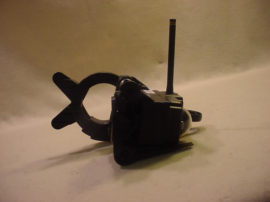
Click to zoom
Application Details
- Equipment Class
- PCB - PCS Licensed Transmitter
- Date of Grant
- May 16, 2007
- Application Purpose
- Original Equipment
- Date of Application
- May 16, 2007
- Equipment Note
- GRID ADVISOR
- Frequency Range
- 959.85000000 - 960.00000000
- Company
- Sensus Metering Systems Inc.
- Country
- United States
Documents & Files
Document Text
Text extracted from the exhibit documents filed with the FCC. Open a document above to read the original.
Users Manual
5015 B.U. Bowman Drive Buford, GA 30518 USA Voice: 770-831-8048 Fax: 770-831-8598 Transmitter Certification Test Report FCC ID: SDBCPRLM01 FCC Rule Part: CFR 47 Part 24 Subpart D, Part 90 Subpart I, Part 101 Subpart C ACS Report Number: 07-0126-LD Applicant: Sensus Metering Systems Model(s): GCVTF Manual The following document and its attachments are considered proprietary and confidential and the Property of Sensus Metering Systems Inc. To be used only for the purpose for which it is submitted. All rights are reserved to Sensus Metering Systems Inc. Reproduction without prior written consent is prohibited. SENSUS CONFIDENTIAL Users Guide Cooper Power Systems FlexNet TM GCVTF 03-14-2007 Sensus Metering Systems Inc DRAFT COPY The following document and its attachments are considered proprietary and confidential and the Property of Sensus Metering Systems Inc. To be used only for the purpose for which it is submitted. All rights are reserved to Sensus Metering Systems Inc. Reproduction without prior written consent is prohibited. SENSUS CONFIDENTIAL The following document and its attachments are considered proprietary and confidential and the Property of Sensus Metering Systems Inc. To be used only for the purpose for which it is submitted. All rights are reserved to Sensus Metering Systems Inc. Reproduction without prior written consent is prohibited. SENSUS CONFIDENTIAL The following document and its attachments are considered proprietary and confidential and the Property of Sensus Metering Systems Inc. To be used only for the purpose for which it is submitted. All rights are reserved to Sensus Metering Systems Inc. Reproduction without prior written consent is prohibited. SENSUS CONFIDENTIAL The following document and its attachments are considered proprietary and confidential and the Property of Sensus Metering Systems Inc. To be used only for the purpose for which it is submitted. All rights are reserved to Sensus Metering Systems Inc. Reproduction without prior written consent is prohibited. SENSUS CONFIDENTIAL The following document and its attachments are considered proprietary and confidential and the Property of Sensus Metering Systems Inc. To be used only for the purpose for which it is submitted. All rights are reserved to Sensus Metering Systems Inc. Reproduction without prior written consent is prohibited. SENSUS CONFIDENTIAL The following document and its attachments are considered proprietary and confidential and the Property of Sensus Metering Systems Inc. To be used only for the purpose for which it is submitted. All rights are reserved to Sensus Metering Systems Inc. Reproduction without prior written consent is prohibited. SENSUS CONFIDENTIAL FlexNet Activation Instructions: Power up the FlexNet 900 Tool unit by pressing the power button. The GPS LINK OK led will begin flashing RED at a 1Hz rate. Carry the unit outside in an area free from overhead obstructions so that the unit can acquire a GPS position fix. (This takes approximately 1~2 minutes) Once the unit has acquired a current GPS fix, the GPS LINK OK led will light solid green. (The light may blink green if the tool temporarily loses a GPS position fix if the tool is brought indoors or there is significant overhead obstructions) Once a GPS fix has been acquired, place the tool against the side of the GCVTF unit as shown in the picture above. The CT should be facing down, and the tool should be placed on the right side of the unit with the “COMMAND METER” text pointing toward the center of the Visual Line Status Indicator (VLI). Press the INSTALL METER button to begin the activation sequence. The sequence is complete when the METER INSTALL OK light illuminates GREEN indicating a successful install. (This process should take approximately 30 seconds) The following document and its attachments are considered proprietary and confidential and the Property of Sensus Metering Systems Inc. To be used only for the purpose for which it is submitted. All rights are reserved to Sensus Metering Systems Inc. Reproduction without prior written consent is prohibited. SENSUS CONFIDENTIAL
Cover Letter(s)
Federal Communications Commission Date 3-19-07 Equipment Authorization Branch 7435 Oakland Mills Road Columbia, MD 21046 Gentlemen: Sensus Metering Systems respectfully requests confidentiality of certain materials provided with the submission of the GCVTF under FCC ID: SDBCPRLM01 in accordance with FCC Regulations 0.459. The confidentiality request applies to the following exhibits: • 07-0126 - Schematics • 07-0126 – Parts List • 07-0126 - Theory of Operation • 07-0126 – Block Diagram • 07-0126 – Tune Up Procedure • 07-0126 – Internal Photos Confidentiality of the internal photographs is requested based on the fact this product is a non-consumer device and is not accessible by the general public. It is only serviceable by the licensee or his designated technicians. The GCVTF has been developed at considerable effort and expense by Sensus Metering Systems. These items are considered as Trade Secrets and therefore public access to the proprietary material could possibly result in duplication of equipment that could severely damage the company’s business advantage. I appreciate your assistance in this matter. Sincerely, Name: William Jones_____________ Signature:_______________________________ Title: _ RF Engineer ________ Date: 3-19-07 Sensus Metering Systems Inc. Communications Group, Santa Barbara 44 Castilian Drive Goleta, Ca 93118 Telephone 805-562-5390 Facsimile 805-562-9134 Date: __03/19/2007_________________________
External Photos
5015 B.U. Bowman Drive Buford, GA 30518 USA Voice: 770-831-8048 Fax: 770-831-8598 Transmitter Certification Test Report FCC ID: SDBCPRLM01 FCC Rule Part: CFR 47 Part 24 Subpart D, Part 90 Subpart I, Part 101 Subpart C ACS Report Number: 07-0126-LD Applicant: Sensus Metering Systems Model(s): GCVTF External Photographs 5015 B.U. Bowman Drive Buford, GA 30518 USA Voice: 770-831-8048 Fax: 770-831-8598 Figure 1: Side1 View 5015 B.U. Bowman Drive Buford, GA 30518 USA Voice: 770-831-8048 Fax: 770-831-8598 Figure 2: Side 2 View 5015 B.U. Bowman Drive Buford, GA 30518 USA Voice: 770-831-8048 Fax: 770-831-8598 Figure3: Front View 5015 B.U. Bowman Drive Buford, GA 30518 USA Voice: 770-831-8048 Fax: 770-831-8598 Figure 4: Rear View 5015 B.U. Bowman Drive Buford, GA 30518 USA Voice: 770-831-8048 Fax: 770-831-8598 Figure 5: Top View 5015 B.U. Bowman Drive Buford, GA 30518 USA Voice: 770-831-8048 Fax: 770-831-8598 Figure 6: Bottom View
ID Label/Location Info
5015 B.U. Bowman Drive Buford, GA 30518 USA Voice: 770-831-8048 Fax: 770-831-8598 Transmitter Certification Test Report FCC ID: SDBCPRLM01 FCC Rule Part: CFR 47 Part 24 Subpart D, Part 90 Subpart I, Part 101 Subpart C ACS Report Number: 07-0126-LD Applicant: Sensus Metering Systems Model(s): GCVTF Label Information Sample Label: (Enlarged to show text detail) Cooper Power Systems Grid Advisor MODEL: GCVTF FCC ID: SDBCPRLM01 IC: 2220A-CPRLM01 This device complies with Part 15 of the FCC Rules and Industry Canada requirements. Operation is subject to the following two condition: (1) This device may not cause harmful interference, and (2) this device must accept any interference received, including interference that may cause undesired operation. This Class B digital apparatus complies with Canadian ICES-003. Cet appareil numdrique de la classe B est conforme a la norme NMB-003 du Canada. 1.75” Cooper Power Systems Grid Advisor MODEL: GCVTF FCC ID: SDBCPRLM01 IC: 2220A-CPRLM01 This device complies with Part 15 of the FCC Rules and Industry Canada requirements. Operation is subject to the following two 1.60 condition: (1) This device may not cause harmful interference, and (2) this device must accept any interference received, including interference that may cause undesired operation. This Class B digital apparatus complies with Canadian ICES-003. Cet appareil numdrique de la classe B est conforme a la norme NMB-003 du Canada. Brady label: Thermal Transfer Printable Labels Permanent Polyimide, B-487 Use the zebra printer in the sand-fuse area Font type – Arial Rounded, Bold Height – 0.070” @ 100% (4.5 pt) Label Location Drawing: Label will be placed on the bottom side of the CPRLM housing as shown in the drawing below.
RF Exposure Info
5015 B.U. Bowman Drive Buford, GA 30518 USA Voice: 770-831-8048 Fax: 770-831-8598 Transmitter Certification Test Report FCC ID: SDBCPRLM01 FCC Rule Part: CFR 47 Part 24 Subpart D, Part 90 Subpart I, Part 101 Subpart C ACS Report Number: 07-0126-LD Applicant: Sensus Metering Systems Model(s): GCVTF RF Exposure Model: GCVTF FCC ID: SDBCPRLM01 5015 B.U. Bowman Drive Buford, GA 30518 USA Voice: 770-831-8048 Fax: 770-831-8598 General Information: Applicant: SENSUS METERING SYSTEMS ACS Project: 07-0126 FCC ID: SDBCPRLM01 Device Category: Fixed Environment: Uncontrolled/General Population Technical Information: Antenna Type: Integral ½ Wave Dipole Antenna Gain: 0.44dBi Max Transmitter Output Power: 30.56 dBm Max System EIRP: 30.56 dBm Operating Configuration: Fixed Mounted Exposure Conditions: Greater than 20cm MPE Calculation The Power Density (mW/cm 2 ) is calculated as follows: S = 2 4R PG π Where: S = power density (in appropriate units, e.g. mW/cm2) P = power input to the antenna (in appropriate units, e.g., mW) G = power gain of the antenna in the direction of interest relative to an isotropic radiator R = distance to the center of radiation of the antenna (appropriate units, e.g., cm) Calculations were performed at low, middle, and high channels within the total band of operation. MPE Calculator for Mobile Equipment Limits for General Population/Uncontrolled Exposure 896.012530.580.601142.880.441.107 200.252 928.92530.390.621093.960.441.107 200.241 959.92529.90.64977.240.441.107 200.215 Power Density (mW/cm^2) Distance (cm) Transmit Frequency (MHz) Radio Power (dBm) Power Density Limit (mW/Cm2) Radio Power (mW) Antenna Gain (dBi) Antenna Gain (mW eq.) Installation Guidelines The installation manual contains the text advising how to install the equipment to maintain compliance with the FCC RF exposure requirements: Conclusion This device complies with the MPE requirements by providing adequate separation between the device, any radiating structure and the general population.
Test Report
5015 B.U. Bowman Drive Buford, GA 30518 USA Voice: 770-831-8048 Fax: 770-831-8598 Transmitter Certification Test Report FCC ID: SDBCPRLM01 FCC Rule Part: CFR 47 Part 24 Subpart D, Part 90 Subpart I, Part 101 Subpart C ACS Report Number: 07-0126-LD Applicant: Sensus Metering Systems Model: GCVTF Test Begin Date: March 19, 2007 Test End Date: March 21, 2007 Report Issue Date: April 3, 2007 FOR THE SCOPE OF ACCREDITATION UNDER LAB Code 200612-0 This report is not be used to claim certification, approval, or endorsement by NVLAP, NIST or any government agency. Prepared by: Reviewed by: Jeff Woods Wireless Certification Engineer ACS, Inc. J. Kirby Munroe Manager Wireless Certifications ACS, Inc. This test report shall not be reproduced except in full. This report may be reproduced in part with prior written consent of ACS, Inc. The results contained in this report are representative of the sample(s) submitted for evaluation. This report contains 41 pages ACS Report: 07-0126-LD Advanced Compliance Solutions Page 2 Table of Content 1.0 General 3 1.1 Purpose 3 1.2 Product Description 3 1.3 Test Methodology 3 1.3.2 In-Band Testing Methodology 3 1.4 Emission Designators 4 2.0 Test Facilities 5 2.1 Location 5 2.2 Laboratory Accreditations/Recognitions/Certifications 5 2.3 Radiated Emissions Test Site Description 6 2.3.1 Semi-Anechoic Chamber Test Site 6 2.3.2 Open Area Tests Site (OATS) 7 2.4 Conducted Emissions Test Site Description 8 3.0 Applicable Standards and References 8 4.0 List of Test Equipment 9 5.0 Support Equipment 10 6.0 EUT Setup and Block Diagram 10 7.0 Summary of Tests 11 7.1 RF Power Output 11 7.1.1 Measurement Procedure 11 7.1.2 Measurement Results 11 7.2 Occupied Bandwidth (Emission Limits) 15 7.2.1 Measurement Procedure 15 7.2.2 Measurement Results 15 7.3 Spurious Emissions at Antenna Terminals 22 7.3.1 Measurement Procedure 22 7.3.2 Measurement Results 22 7.4 Field Strength of Spurious Emissions 28 7.4.1 Measurement Procedure 28 7.4.2 Measurement Results 28 7.5 Frequency Stability 33 7.5.1 Measurement Procedure 33 7.5.2 Measurement Results 33 7.6 Radiated Emissions (Unintentional Radiators) 41 7.6.1 Measurement Procedure 41 7.6.2 Measurement Results 41 8.0 Conclusion 41 Additional Exhibits Included In Filing Internal Photographs External Photographs Tune-up Procedure Test Setup Photographs Product Labeling RF Exposure – MPE Calculations Installation/Users Guide System Block Diagram Theory of Operation Parts List Schematics Model: GCVTF FCC ID: SDBCPRLM01 ACS Report: 07-0126-LD Advanced Compliance Solutions Page 3 1.0 GENERAL 1.1 Purpose The purpose of this report is to demonstrate compliance with Part 2 Subpart J, Part 24 Subpart D, Part 90 Subpart I, and Part 101 Subpart C of the FCC’s Code of Federal Regulations. 1.2 Product Description The FlexNet Distribution Monitor consists of a printed circuit board, Cooper Line Monitor (CPRLM) transmitter, model GCVTF. This board contains the power supply, transmitter, and line monitor circuitry. The unit has an external permanently attached antenna with the following specifications: Center Freq. 916MHz Bandwidth 80MHz Wavelength 1/2-wave VSWR <1.9 typ. at center Impedance 50 ohms Gain 0.44dBi Connection RG-178 coax Polarization Vertical The device will be powered via a Current Transformer (CT) fed into the housing which has a spring loaded clamp that allows it to easily attach to existing power lines. A minimally sized AA lithium battery will be included to facilitate installation transmission and transmissions during power outages. The device communicates via the Sensus fixed wireless telemetry network to provide line status information to utilities. The device will transmit status (Health) information automatically at a programmable periodic rate and also when triggered by specific events such as a change of sensor status such as a high current event called a fault. 1.3 Test Methodology 1.3.1 In-Band Testing Methodology For testing in accordance with 47 CFR 2.1046-2.1057, OET/Lab recommends that the following be used to select test frequencies for licensed devices: Frequency range over which device operates Number of frequencies Location in the range of operation 1 MHz or less 1 Middle 1 to 10 MHz 2 1 near top and 1 near bottom 10 to 100 MHz 3 1 near top, 1 near middle and 1 near bottom Model: GCVTF FCC ID: SDBCPRLM01 ACS Report: 07-0126-LD Advanced Compliance Solutions Page 4 The GCVTF is designed to operate in multiple bands under the requirements of CFR 47 Parts 24, 90, and 101. The following is a list of the frequency bands of operation sorted based on the FCC rule parts in which the band is associated. CFR Title 47 Rule Part Frequency Band of Operation (MHz) 24D 901.0 - 902.0 24D 930.0 - 931.0 24D 940.0 - 941.0 90 896.0125 - 901.0 90 935.0 - 940.0 101 928.85 - 929.0 101 932.0 - 932.5 101 941.0 - 941.5 101 959.85 - 960.0 Based on the requirements set forth in accordance 47 CFR 2.1046-2.1057 as stated above, the methodology in selecting the places to test in the available bands of operation is outlined in the following table. CFR Title 47 Rule Part Frequency Band of Operation (MHz) Location in the Range of Operation 90 896.0125 - 901.0 24D 901.0 - 902.0 1 near top and 1 near bottom 101 928.85 - 929.0 Middle 24D 930.0 - 931.0 Middle 101 932.0 - 932.5 Middle 90 935.0 - 940.0 24D 940.0 - 941.0 101 941.0 - 941.5 1 near top and 1 near bottom 101 959.85 - 960.0 Middle The data provided in this report is sorted based on the rule part. 1.4 Emission Designators The GCVTF transmitter produces four distinct modulation formats. The necessary bandwidth calculations for these formats may be found in a separate document. The emissions designators for the four modulation types used by the GCVTF Transmitter are as follows: EMISSIONS DESIGNATORS: Normal Mode: 9K60F2D Half-Baudrate Mode: 4K80F2D Boost Mode: 1K10F2D MPass Mode: 5K90F1D Model: GCVTF FCC ID: SDBCPRLM01 ACS Report: 07-0126-LD Advanced Compliance Solutions Page 5 2.0 TEST FACILITIES 2.1 …
Text truncated - open the document above for the full version.
Test Setup Photos
5015 B.U. Bowman Drive Buford, GA 30518 USA Voice: 770-831-8048 Fax: 770-831-8598 Transmitter Certification Test Report FCC ID: SDBCPRLM01 FCC Rule Part: CFR 47 Part 24 Subpart D, Part 90 Subpart I, Part 101 Subpart C ACS Report Number: 07-0126-LD Applicant: Sensus Metering Systems Model(s): GCVTF Test Set Up Photos 5015 B.U. Bowman Drive Buford, GA 30518 USA Voice: 770-831-8048 Fax: 770-831-8598 Figure 1: Intentional Radiated Emissions 5015 B.U. Bowman Drive Buford, GA 30518 USA Voice: 770-831-8048 Fax: 770-831-8598 Figure 2: Intentional Radiated Emissions 5015 B.U. Bowman Drive Buford, GA 30518 USA Voice: 770-831-8048 Fax: 770-831-8598 Figure 3: Intentional Radiated Emissions – Substitution 5015 B.U. Bowman Drive Buford, GA 30518 USA Voice: 770-831-8048 Fax: 770-831-8598 Figure 4: Unintentional Radiated Emissions. 5015 B.U. Bowman Drive Buford, GA 30518 USA Voice: 770-831-8048 Fax: 770-831-8598 Figure 5: Unintentional Radiated Emissions.
Contact Information
Applicant
Ray Britt(Senior Director, Global System Test)
Technical Specifications
| # | Rule Parts | Frequency Range | Power Output | Emission | Tolerance |
|---|---|---|---|---|---|
| 17 | 101C | 959.85 MHz - 960 MHz | 1 W | 5K90F1D | 1.5 ppm |
Other Applications from Sensus Metering Systems Inc.

SDBCL202
Mar 09, 2026Command Link II Wireless Interface
Equipment Class
PCB - PCS Licensed Transmitter
SDBWFL3
Mar 04, 2026Remote Telemetry Module
Equipment Class
DTS - Digital Transmission SystemSDBIDTB007
Sep 28, 2023Stratus IQ+ Radio Module
Equipment Class
PCB - PCS Licensed Transmitter
SDBM420V01
Jan 05, 2023Base Station Transceiver
Equipment Class
PCB - PCS Licensed Transmitter
SDBM420V00
Jan 05, 2023Base Station Transceiver
Equipment Class
PCB - PCS Licensed Transmitter