SDBTGB001HPBASE STATION TRANSCEIVER
Sensus Metering Systems Inc.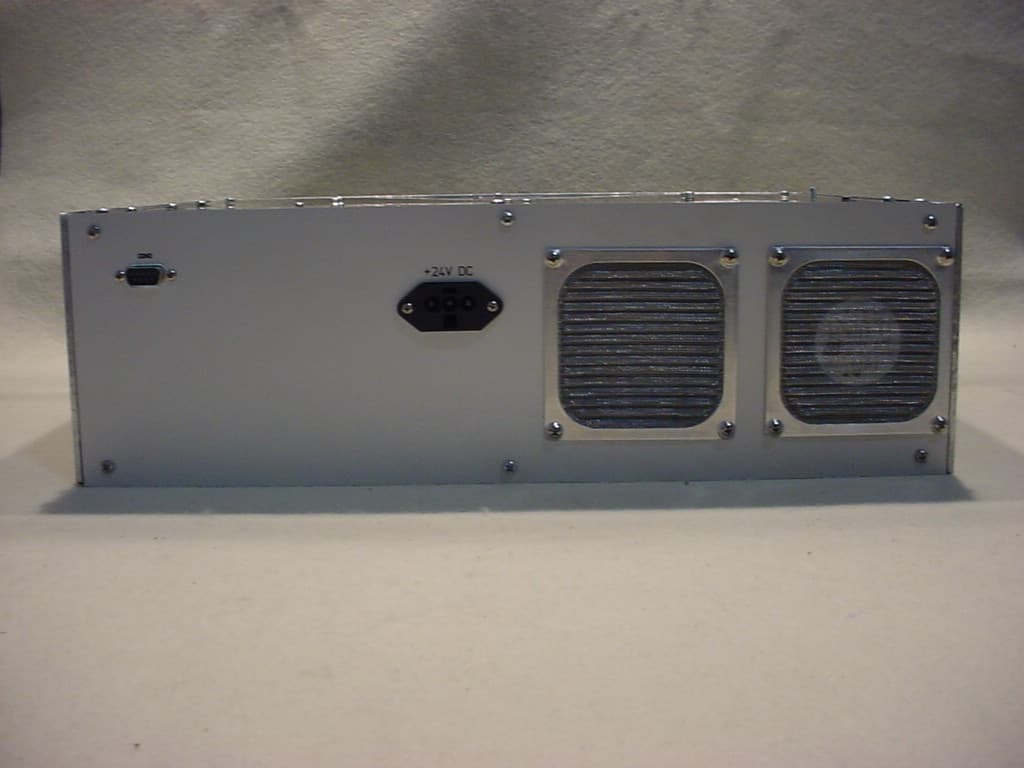
Click to zoom
Application Details
- Equipment Class
- PCB - PCS Licensed Transmitter
- Date of Grant
- Jun 14, 2005
- Application Purpose
- Original Equipment
- Date of Application
- Jun 14, 2005
- Equipment Note
- BASE STATION TRANSCEIVER
- Frequency Range
- 959.85000000 - 960.00000000
- Company
- Sensus Metering Systems Inc.
- Country
- United States
Documents & Files
Document Text
Text extracted from the exhibit documents filed with the FCC. Open a document above to read the original.
Users Manual
5015 B.U. Bowman Drive Buford, GA 30518 USA Voice: 770-831-8048 Fax: 770-831-8598 Transmitter Certification Test Report FCC ID: SDBTGB001LP/SDBTGB001HP FCC Rule Part: CFR 47 Part 24 Subpart D, Part 90 Subpart I, Part 101 Subpart C ACS Report Number: 05-0169-LP/05-0169-HP Manufacturer: Advanced Metering Data Systems, LLC Equipment Type: Base Station Transceiver Model(s): TGB001LP TGB001HP Users Manual 1 To be used only for the purpose for which it is submitted. All rights reserved to AMDS LLC. Reproduction without written consent is prohibited. AMDS CONFIDENTIAL TGB 900MHz Users Manual & Operators Guide Prepared by: AMDS 2021 Lakeshore Dr. Suite 414 New Orleans, LA 70122 PH: (504)304-2502 2 To be used only for the purpose for which it is submitted. All rights reserved to AMDS LLC. Reproduction without written consent is prohibited. AMDS CONFIDENTIAL 1. DESCRIPTION 1.1. Purpose The purpose of this document is to provide necessary information for use by field personnel in the installation, operation, and troubleshooting of the 900MHz Cell Tower Gateway Basestation (TGB). 3 To be used only for the purpose for which it is submitted. All rights reserved to AMDS LLC. Reproduction without written consent is prohibited. AMDS CONFIDENTIAL 1.2. FCC Class B Statement “NOTE: This equipment has been tested and found to comply with the limits for a Class B digital device, pursuant to Part 15 of the FCC Rules. These limits are designed to provide reasonable protection against harmful interference in a residential installation. This equipment generates, uses, and can radiate radio frequency energy and, if not installed and used in accordance with the instructions, may cause harmful interference to radio communications. However, there is no guarantee that interference will not occur in a particular installation. If this equipment does cause harmful interference to radio or television reception, which can be determined by turning the equipment off and on, the user is encouraged to try to correct the interference by one or more of the following measures: • Reorient or relocate the receiving antenna. • Increase the separation between the equipment and receiver. • Connect the equipment into an outlet on a circuit different from that to which the receiver is connected. • Consult the dealer or an experienced radio/TV technician for help. Warning: Changes or modifications to this device not expressly approved by AMDS could void the user’s authority to operate the equipment. RF Exposure In accordance with FCC requirements of human exposure to radiofrequency fields, the radiating element shall be installed such that a minimum separation distance of: • For HP Models (i.e. FCC ID and IC ID’s end in “HP”) a distance of 2.5 meters. • For LP Models (i.e. FCC ID and IC ID’s end in “LP”) a distance of 0.5 meters. Note: These limits are for CFR 47 Part 90 and Par101 operation. CFR 47 Part 24 limits will be addressed at time of licensing according to Part 1.1307 of CFR 47. This information presented is correct for all three Rule Parts. 4 To be used only for the purpose for which it is submitted. All rights reserved to AMDS LLC. Reproduction without written consent is prohibited. AMDS CONFIDENTIAL 1.3. Industry Canada This Class B digital apparatus meets all requirements of the Canadian Interference Causing Equipment Regulations. Operation is subject to the following two conditions: (1) this device may not cause harmful interference, and (2) this device must accept any interference received, including interference that may cause undesired operation. Cet appareillage numérique de la classe B répond à toutes les exigences de l'interférence canadienne causant des règlements d'équipement. L'opération est sujette aux deux conditions suivantes: (1) ce dispositif peut ne pas causer l'interférence nocive, et (2) ce dispositif doit accepter n'importe quelle interférence reçue, y compris l'interférence qui peut causer l'opération peu désirée. 1.4. Specifications 1.4.1. Input Power 1.4.1.1. Voltage: 24VDC 1.4.1.2. Input Current 10A max (at low input voltage range) Approximately 3A continuous 1.4.1.3. Alarms and Controls Low-voltage alarm is asserted when output voltage drops below 22VDC. Low-voltage disconnect is asserted when output voltage drops below 20VDC, re-connects when output voltage exceeds 22VDC. 1.4.2. Environmental 1.4.2.1. Operating temperature -40 ̊C to +85 ̊C 1.4.2.2. Storage temperature -40 ̊C to +85 ̊C 1.4.2.3. Humidity 0% to 95%, non-condensing 5 To be used only for the purpose for which it is submitted. All rights reserved to AMDS LLC. Reproduction without written consent is prohibited. AMDS CONFIDENTIAL 1.4.3 General Information The TGB Transceiver is a high performance burst data radio system. The RF receiver is configured to receive 3 distinct modulation schemes on 3 adjacent frequencies in the 896 to 940 MHz frequency range. The TGB RF Transmitter operates on a single configurable channel (12.5kHz, 13.6 KHz, or 25kHz authorized bandwidth depending on the channel and FCC Rule section governing it’s operation) in the 935 to 960 MHz frequency range. The transmitter utilizes yet another type of modulation scheme, different from the three utilized by the receiver. Transmitted and received data messages are short in nature, meaning that the radio is intended for burst telemetry type of applications. Larger packets may, however, be transmitted by sending successive packets. The TGB operates as a multi-channel transceiver in a “cellular” type system. The TGB assembles the received messages and forwards them to the TGB Controller (one per city) via local phone lines. The TGB Controller eliminates redundant messages (i.e., messages from endpoints that were received by more than one TGB) before forwarding them to the NOC via a high-speed connection (ISDN, T1, etc). The TGB shall also notify the NOC of any alarm indications, such as tamper/intrusion, temperature alarms, or power failure. The TGB is installed inside an equip…
Text truncated - open the document above for the full version.
Users Manual
5015 B.U. Bowman Drive Buford, GA 30518 USA Voice: 770-831-8048 Fax: 770-831-8598 Transmitter Certification Test Report FCC ID: SDBTGB001LP/SDBTGB001HP FCC Rule Part: CFR 47 Part 24 Subpart D, Part 90 Subpart I, Part 101 Subpart C ACS Report Number: 05-0169-LP/05-0169-HP Manufacturer: Advanced Metering Data Systems, LLC Equipment Type: Base Station Transceiver Model(s): TGB001LP TGB001HP Users Manual 1 To be used only for the purpose for which it is submitted. All rights reserved to AMDS LLC. Reproduction without written consent is prohibited. TGB 900Mhz Users Manual & Operators Guide Prepared by: AMDS 2021 Lakeshore Dr. Suite 414 New Orleans, LA 70122 PH: (504)304-2502 2 To be used only for the purpose for which it is submitted. All rights reserved to AMDS LLC. Reproduction without written consent is prohibited. 1. DESCRIPTION 1.1. Purpose The purpose of this document is to provide necessary information for use by field personnel in the installation, operation, and troubleshooting of the 900MHz Cell Tower Gateway Basestation (TGB). 3 To be used only for the purpose for which it is submitted. All rights reserved to AMDS LLC. Reproduction without written consent is prohibited. 1.2. FCC Class B Statement “NOTE: This equipment has been tested and found to comply with the limits for a Class B digital device, pursuant to Part 15 of the FCC Rules. These limits are designed to provide reasonable protection against harmful interference in a residential installation. This equipment generates, uses, and can radiate radio frequency energy and, if not installed and used in accordance with the instructions, may cause harmful interference to radio communications. However, there is no guarantee that interference will not occur in a particular installation. If this equipment does cause harmful interference to radio or television reception, which can be determined by turning the equipment off and on, the user is encouraged to try to correct the interference by one or more of the following measures: • Reorient or relocate the receiving antenna. • Increase the separation between the equipment and receiver. • Connect the equipment into an outlet on a circuit different from that to which the receiver is connected. • Consult the dealer or an experienced radio/TV technician for help. Warning: Changes or modifications to this device not expressly approved by AMDS could void the user’s authority to operate the equipment. 1.3. Industry Canada This Class B digital apparatus meets all requirements of the Canadian Interference Causing Equipment Regulations. Operation is subject to the following two conditions: (1) this device may not cause harmful interference, and (2) this device must accept any interference received, including interference that may cause undesired operation. Cet appareillage numérique de la classe B répond à toutes les exigences de l'interférence canadienne causant des règlements d'équipement. L'opération est sujette aux deux conditions suivantes: (1) ce dispositif peut ne pas causer l'interférence nocive, et (2) ce dispositif doit accepter n'importe quelle interférence reçue, y compris l'interférence qui peut causer l'opération peu désirée. 4 To be used only for the purpose for which it is submitted. All rights reserved to AMDS LLC. Reproduction without written consent is prohibited. 1.4. Specifications 1.4.1. Input Power 1.4.1.1. Voltage 20-28VDC (nominally 24V) 1.4.1.2. Input Current 8A max Approximately 3A continuous 1.4.1.3. Alarms and Controls Low-voltage alarm is asserted when output voltage drops below 22VDC. Low-voltage disconnect is asserted when output voltage drops below 20VDC, re-connects when output voltage exceeds 22VDC. 1.4.2. Environmental 1.4.2.1. Operating temperature -40 ̊C to +85 ̊C 1.4.2.2. Storage temperature -40 ̊C to +85 ̊C 1.4.2.3. Humidity 0% to 95%, non-condensing 5 To be used only for the purpose for which it is submitted. All rights reserved to AMDS LLC. Reproduction without written consent is prohibited. General The TGB Transceiver is a high performance burst data radio system. The RF receiver is configured to receive 3 distinct modulation schemes on 3 adjacent frequencies in the 896 to 940 MHz frequency range. The TGB RF Transmitter operates on a single configurable channel (12.5kHz, 13.6 KHz, or 25kHz authorized bandwidth depending on the channel and FCC Rule section governing it’s operation) in the 935 to 960 MHz frequency range. The transmitter utilizes yet another type of modulation scheme, different from the three utilized by the receiver. Transmitted and received data messages are short in nature, meaning that the radio is intended for burst telemetry type of applications. Larger packets may, however, be transmitted by sending successive packets. The TGB operates as a multi-channel transceiver in a “cellular” type system. The TGB assembles the received messages and forwards them to the TGB Controller (one per city) via local phone lines. The TGB Controller eliminates redundant messages (i.e., messages from endpoints that were received by more than one TGB) before forwarding them to the NOC via a high-speed connection (ISDN, T1, etc). The TGB shall also notify the NOC of any alarm indications, such as tamper/intrusion, temperature alarms, or power failure. 6 To be used only for the purpose for which it is submitted. All rights reserved to AMDS LLC. Reproduction without written consent is prohibited. 1.5. Block Diagram 1.5.1. Power System !!! Danger !!! Hazardous AC voltages capable of producing severe electrical shock are present at various locations in the TGB. Exercise caution when working inside the enclosure, to assure that contact is not made with and electrical termination. !!! Warning !!! The batteries are a source of energy and can be hazardous if shorted. Exercise caution. 1.5.1.1. AC Power – Indoor AC Power is supplied to the rectifier through a rack mounted power strip with integral ON/OFF switch and surge protection. 1.5.1.2. AC Power – Outdoor AC P…
Text truncated - open the document above for the full version.
Cover Letter(s)
Federal Communications Commission May 13, 2005 Equipment Authorization Branch 7435 Oakland Mills Road Columbia, MD 21046 Gentlemen: AMDS LLC respectfully requests confidentiality of certain materials provided with the submission of the TGB001HP under FCC ID: SDBTGB001HP in accordance with FCC Regulations 0.459. The confidentiality request applies to the following: • Schematics • Parts List • Theory of Operations • System Block Diagram • Tune-Up Procedure • Any other documents marked “confidential” on the documents themselves. The TGB001HP has been developed at considerable effort and expense by AMDS LLC. These items are considered as Trade Secrets and therefore public access to the proprietary material could possibly result in duplication of equipment that could severely damage the company’s business advantage. I appreciate your assistance in this matter. Sincerely, Name: Robert J. Davis_____________ Signature:_______________________________ Title:__Principal RF Engineer ________ Date:__05/13/2005_________________________ ADVANCED METERING DATA SYSTEMS, LLC 2021 LAKESHORE DRIVE, SUITE 414 NEW ORLEANS, LA 70122 504 304 2502 PHONE 504 304 2432 FAX
External Photos
5015 B.U. Bowman Drive Buford, GA 30518 USA Voice: 770-831-8048 Fax: 770-831-8598 Transmitter Certification Test Report FCC ID: SDBTGB001LP/ SDBTGB001HP FCC Rule Part: CFR 47 Part 24 Subpart D, Part 90 Subpart I, Part 101 Subpart C ACS Report Number: 05-0169-LP/05-0169-HP Manufacturer: Advanced Metering Data Systems, LLC Equipment Type: Base Station Transceiver Model(s): TGB001LP TGB001HP External Photographs Model: TGB001LP/HP Advanced Compliance Solutions FCC ID: SDBTGB001LP/HP 5015 B.U. Bowman Drive Buford, GA 30518 USA Voice: 770-831-8048 Fax: 770-831-8598 Figure 1. Front View Model: TGB001LP/HP Advanced Compliance Solutions FCC ID: SDBTGB001LP/HP 5015 B.U. Bowman Drive Buford, GA 30518 USA Voice: 770-831-8048 Fax: 770-831-8598 Figure 2. Rear View
ID Label/Location Info
5015 B.U. Bowman Drive Buford, GA 30518 USA Voice: 770-831-8048 Fax: 770-831-8598 Transmitter Certification Test Report FCC ID: SDBTGB001HP FCC Rule Part: CFR 47 Part 24 Subpart D, Part 90 Subpart I, Part 101 Subpart C ACS Report Number: 05-0169-HP Manufacturer: Advanced Metering Data Systems, LLC Equipment Type: Base Station Transceiver Model: TGB001HP Label Information Model: TGB001HP Advanced Compliance Solutions FCC ID: SDBTGB001HP 5015 B.U. Bowman Drive Buford, GA 30518 USA Voice: 770-831-8048 Fax: 770-831-8598 Figure 1. Label Information Figure 2. Label Placement FCC ID: SDBTGB001HP THIS DEVICE COMPLIES WITH PART 15 OF THE FCC RULES. OPERATION IS SUBJECT TO THE FOLLOWING TWO CONDITIONS. (1) THIS DEVICE MAY NOT CAUSE HARMFUL INTERFERENCE, AND (2) THIS DEVICE MUST ACCEPT ANY INTERFERENCE RECEIVED, INCLUDING INTERFERENCE THAT MAY CAUSE UNDESIRED OPERATION. IC: 5733A-TGB001 This Class [*] digital apparatus complies with Canadian ICES-003. Cet appareil numérique de la classe [*] est conforme à la norme NMB-003 du Canada. Label Position
Internal Photos
5015 B.U. Bowman Drive Buford, GA 30518 USA Voice: 770-831-8048 Fax: 770-831-8598 Transmitter Certification Test Report FCC ID: SDBTGB001LP/ SDBTGB001HP FCC Rule Part: CFR 47 Part 24 Subpart D, Part 90 Subpart I, Part 101 Subpart C ACS Report Number: 05-0169-LP/05-0169-HP Manufacturer: Advanced Metering Data Systems, LLC Equipment Type: Base Station Transceiver Model(s): TGB001LP TGB001HP Internal Photographs Model: TGB001LP/HP Advanced Compliance Solutions FCC ID: SDBTGB001LP/HP 5015 B.U. Bowman Drive Buford, GA 30518 USA Voice: 770-831-8048 Fax: 770-831-8598 Figure 1. RF Board Front Model: TGB001LP/HP Advanced Compliance Solutions FCC ID: SDBTGB001LP/HP 5015 B.U. Bowman Drive Buford, GA 30518 USA Voice: 770-831-8048 Fax: 770-831-8598 Figure 2. RF Board Front – No Shields Model: TGB001LP/HP Advanced Compliance Solutions FCC ID: SDBTGB001LP/HP 5015 B.U. Bowman Drive Buford, GA 30518 USA Voice: 770-831-8048 Fax: 770-831-8598 Figure 3. RF Board Back Model: TGB001LP/HP Advanced Compliance Solutions FCC ID: SDBTGB001LP/HP 5015 B.U. Bowman Drive Buford, GA 30518 USA Voice: 770-831-8048 Fax: 770-831-8598 Figure 4. Power Amplifier (Only used in TGB001HP)
Test Report
5015 B.U. Bowman Drive Buford, GA 30518 USA Voice: 770-831-8048 Fax: 770-831-8598 Transmitter Certification Test Report FCC ID: SDBTGB001HP FCC Rule Part: CFR 47 Part 24 Subpart D, Part 90 Subpart I, Part 101 Subpart C ACS Report Number: 05-0169-HP Manufacturer: Advanced Metering Data Systems, LLC Equipment Type: Base Station Transceiver Model: TGB001HP Test Dates: May 9, 2005 – May 13, 2005 Report Issue Date: May 17, 2005 FOR THE SCOPE OF ACCREDITATION UNDER LAB Code 200612 Prepared by: Reviewed by: J. Kirby Munroe Manager Wireless Certifications ACS, Inc. R. Sam Wismer Engineering Manager ACS, Inc. This test report shall not be reproduced except in full. This report may be reproduced in part with prior written consent of ACS, Inc. The results contained in this report are representative of the sample(s) submitted for evaluation. This report contains 25 pages ACS Report: 05-0169-HP Advanced Compliance Solutions Page 2 Table of Contents 1.0 General 3 1.1 Purpose 3 1.2 Product Description 3 1.3 Emission Designator 3 1.4 Product Modifications 3 2.0 Test Facilities 4 2.1 Location 4 2.2 Laboratory Accreditations/Recognitions/Certifications 4 2.3 Radiated Emissions Test Site Description 4 2.3.1 Semi-Anechoic Chamber Test Site 4 2.3.2 Open Area Tests Site (OATS) 5 2.4 Conducted Emissions Test Site Description 6 3.0 Applicable Standards and References 7 4.0 List of Test Equipment 8 5.0 Support Equipment 9 6.0 EUT Setup and Block Diagram 9 7.0 Summary of Tests 10 7.1 RF Power Output 10 7.1.1 Measurement Procedure 10 7.1.2 Measurement Results 10 7.2 Occupied Bandwidth (Emission Limits) 14 7.2.1 Measurement Procedure 14 7.2.2 Measurement Results 14 7.3 Spurious Emissions at Antenna Terminals 18 7.3.1 Measurement Procedure 18 7.3.2 Measurement Results 18 7.4 Field Strength of Spurious Emissions 21 7.4.1 Measurement Procedure 21 7.4.2 Measurement Results 21 7.5 Frequency Stability 23 7.5.1 Measurement Procedure 23 7.5.2 Measurement Results 23 7.6 Radiated Emissions (Unintentional Radiators) 24 7.6.1 Measurement Procedure 24 7.6.2 Measurement Results 24 7.7 Power Line Conducted Emissions 25 Additional Exhibits Included In Filing Internal Photographs External Photographs Test Setup Photographs Product Labeling RF Exposure – MPE Calculations Installation/Users Guide System Block Diagram Theory of Operation Parts List Schematics Tune-up Procedure Model: TGB001HP FCC ID: SDBTGB001HP ACS Report: 05-0169-HP Advanced Compliance Solutions Page 3 1.0 GENERAL 1.1 Purpose The purpose of this report is to demonstrate compliance with Part 2 Subpart J, Part 24 Subpart D, Part 90 Subpart I, and Part 101 Subpart C of the FCC’s Code of Federal Regulations. 1.2 Product Description The AMDS TGB Transceiver is the base station component of the AMDS Automated Meter Reading (AMR) and Telemetry System. The device receives telemetry transmissions from multiple system end point units. These units are mostly utilized for utility metering, but in some cases may send other types of information such as that used for inventory and industrial control applications. The end points may initiate transmissions to the TGB upon their own initiative (using an ALOHA protocol for transmission) or may be commanded by the TGB transmission to the end points to transmit upon demand. The TGB may also transmit command information to the end point units that may or may not result in a subsequent end point transmission (i.e. system synchronization information). The Transmitter section of the TGB transceiver utilizes GFSK modulation to communicate with the end point devices at one or two output power levels (different model numbers identify the transmit output power levels) of 45 dBm or 31 dBm. The transmitter emission designator is 5K90F1D. The TGB transceiver is housed in a 19 inch, rack mountable, enclosure that contains an RF PCB that provides the RF Transmit and Receive functionality, an Analog To Digital Converter Card (A2D) that digitizes the IF output of the RF PCB, two Channel Processor Cards (CPC) that utilize DSP techniques to demodulate the base band, sampled, IF signal, a Fusion Processor section containing a Linux based computer that collects received messages from the CPC cards and commands the RF card setup and data transfer tasks for the transmitter section. Detailed photographs of the EUT are filed separately with this filing. 1.3 Emission Designator The emissions designator for the TGB Transceiver is as follows: GFSK Modulation: 5K90F1D 1.4 Product Modifications In order for the TGB transceiver base station to comply to radiated emission limits for CFR 47 Part 15 Subpart B for unintentional radiators the following modifications were made: • Ferrite bead added to I/O board ribbon near back. • Ferrite bead added to I/O board CAT5 cable wrapped toward the front near the I/O board. • 8 strips of gasketing were used on all the seams. 2 on each side. Gasketing Material: Chomerics, M/N: Softshield 5000, P/N: 82-122-74037-02400 or Instrument Specialties, P/N: 8422-0151-26 Ferrite Beads: On Ethernet is Steward 28B1000-000 On ribbon cable is Steward 28S2023-0M0 Model: TGB001HP FCC ID: SDBTGB001HP ACS Report: 05-0169-HP Advanced Compliance Solutions Page 4 2.0 TEST FACILITIES 2.1 Location The radiated and conducted emissions test sites are located at the following address: Advanced Compliance Solutions 5015 B.U. Bowman Drive Buford, GA 30518 Phone: (770) 831-8048 Fax: (770) 831-8598 2.2 Laboratory Accreditations/Recognitions/Certifications The Semi-Anechoic Chamber Test Site, Open Area Test Site (OATS) and Conducted Emissions Site have been fully described, submitted to, and accepted by the FCC, Industry Canada and the Japanese Voluntary Control Council for Interference by information technology equipment. In addition, ACS is compliant to ISO 17025 as certified by the National Institute of Standards and Technology under their National Voluntary Laboratory Accreditation Program. The following certification numbers have been issued in recogniti…
Text truncated - open the document above for the full version.
Contact Information
Applicant
Ray Britt(Senior Director, Global System Test)
Test Firm
Advanced Compliance Solutions, Inc.Douglas Massey
Technical Specifications
| # | Rule Parts | Frequency Range | Power Output | Emission | Tolerance |
|---|---|---|---|---|---|
| 5 | 101C | 959.85 MHz - 960 MHz | 31.84 W | 5K90F1D | 1.5 ppm |
Other Applications from Sensus Metering Systems Inc.

SDBCL202
Mar 09, 2026Command Link II Wireless Interface
Equipment Class
PCB - PCS Licensed Transmitter
SDBWFL3
Mar 04, 2026Remote Telemetry Module
Equipment Class
DTS - Digital Transmission SystemSDBIDTB007
Sep 28, 2023Stratus IQ+ Radio Module
Equipment Class
PCB - PCS Licensed Transmitter
SDBM420V01
Jan 05, 2023Base Station Transceiver
Equipment Class
PCB - PCS Licensed Transmitter
SDBM420V00
Jan 05, 2023Base Station Transceiver
Equipment Class
PCB - PCS Licensed Transmitter