SDBZIGMOD10Inline Zigbee Module
Sensus Metering Systems Inc.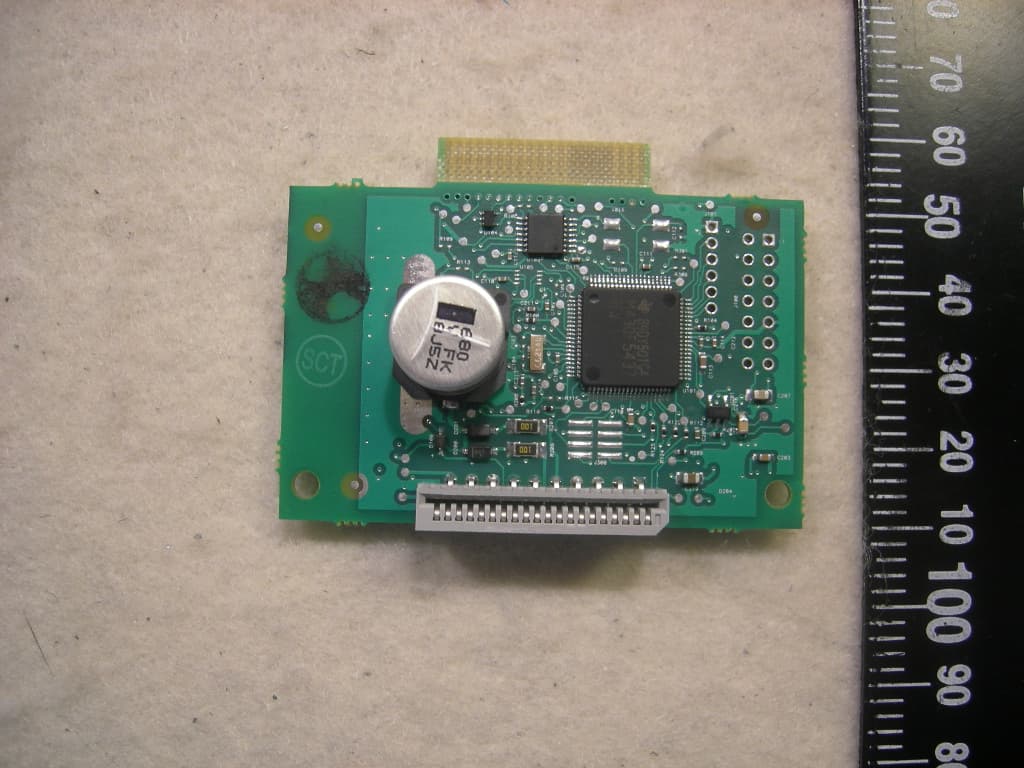
Click to zoom
Application Details
- Equipment Class
- DTS - Digital Transmission System
- Date of Grant
- Sep 22, 2010
- Application Purpose
- Original Equipment
- Date of Application
- Sep 22, 2010
- Equipment Note
- Inline Zigbee Module
- Frequency Range
- 2405.00000000 - 2480.00000000
- Company
- Sensus Metering Systems Inc.
- Country
- United States
Documents & Files
Document Text
Text extracted from the exhibit documents filed with the FCC. Open a document above to read the original.
Users Manual
5015 B.U. Bowman Drive Buford, GA 30518 USA Voice: 770-831-8048 Fax: 770-831-8598 Certification Exhibit FCC ID: SDBZIGMOD10 IC: 2220A-ZIGMOD10 FCC Rule Part: 15.247 IC Radio Standards Specification: RSS-210 ACS Report Number: 10-0020.W06.11.A Manufacturer: Sensus Metering Systems, Inc. Model: ZIGMOD10 Manual Inline Zigbee Module – User Manual [FCC ID: SDBZIGMOD10, IC: 2220A-ZIGMOD10] Revision 2.1, 20 September, 2010 Sensus Sensus Sensus Sensus USA USAUSA USA This document contains proprietary information. It may not be copied, transmitted or distributed, in whole or in part, without the consent of Sensus USA REVISION SUMMARY Date Author Change Description August 14, 2009 BG Baseline September 15, 2009 JAS Corrected Label information and added label Placement September 14, 2010 JAS Corrected antenna gain stipulation from 2 to 0dBi. September 20, 2010 JAS Corrected Label Information and Front Page Sensus In-Line Zigbee Module – User Manual 3 1.0 Introduction This document details the installation and usage of the “Sensus In-Line Zigbee Module”. At present the module is designed to work in the Sensus iConA and iConAS electric meters although in future in may work with other electric meter designs. The module is designed to sit between the sensor board and the display board within the electric meter. When a Zigbee module is not installed a ribbon cable connects the sensor and display. In the case when the module is installed the module is connected between the sensor and display, to give the electric meter Zigbee functionality. Sensus In-Line Zigbee Module – User Manual 4 2.0 Installation of the module within an electric meter First remove the meter outer cover. Carefully remove the meter inner cover. Disconnect the ribbon cable from the sensor pcb. Insert the Zigbee board into the connector that the display ribbon has been disconnected from. Insert the free end of the ribbon cable into the connector on the Zigbee module as shown in Figure 1. Add the jumper (short) to position J202 on the sensor board, as shown in Figure 2. Figure 1 – Zigbee module installed in a meter Sensus In-Line Zigbee Module – User Manual 5 Figure 2 – Jumper must be fitted Sensus In-Line Zigbee Module – User Manual 6 3.0 Module pin-out description Pin Pin Pin Pin Number NumberNumber Number Ribbon Connector Ribbon ConnectorRibbon Connector Ribbon Connector Board Edge Connector Board Edge ConnectorBoard Edge Connector Board Edge Connector De DeDe Description scriptionscription scription 1 11 1 MAINS_SENSE MAINS_SENSE Pass through 2 22 2 RELAY_TRIGGER RELAY_TRIGGER Pass through 3 33 3 RELAY_SWITCH_SENSE RELAY_SWITCH_SENSE Pass through 4 44 4 GROUND EXTRA_CS Ribbon is grounded. Board edge is a 5V active high interrupt line to the Zigbee module. 5 55 5 GROUND GROUND Power (Pass through) 6 66 6 GROUND GROUND Power (Pass through) 7 77 7 GROUND GROUND Power (Pass through) 8 88 8 GROUND GROUND Power (Pass through) 9 99 9 26V_12S 26V_12S 26V from 12S base (pass through) 10 1010 10 26V_2S 26V_2S 26V from 2S base (pass through) 11 1111 11 5V0 5V0 5V supply to the sensor 12 1212 12 GROUND GROUND Power (Pass through) 13 1313 13 7759_CF 7759_CF Sensor board 14 1414 14 ZIGBEE IRQ ZIGBEE IRQ Zigbee module IRQ 15 1515 15 SPI_DATA_OUT SPI_DATA_OUT Sensor SPI Data Bus Sensus In-Line Zigbee Module – User Manual 7 16 1616 16 7759_ZX 7759_ZX Sensory Zero Crossing Indictor 17 1717 17 NOT USED NOT USED 18 1818 18 NOT USED NOT USED 19 1919 19 SPI_CLOCK SPI_CLOCK Sensor SPI Clock 20 2020 20 SPI_DATA_IN SPI_DATA_IN Sensor SPI Data Appendix A General Statements Warning: Changes or modifications to this device not expressly approved by Sensus USA could void the user’s authority to operate the equipment. NOTE: This equipment has been tested and found to comply with the limits for a Class B digital device, pursuant to part 15 of the FCC rules. These limits are designed to provide reasonable protection against harmful interference in a residential installation. This equipment generates, uses, and can radiate radio frequency energy and, if not installed and used in accordance with the instruction, may cause harmful interference to radio or television reception, which can be determined by turning the equipment off and on, the user is encouraged to try to correct the interference by one or more of the following measures: • Reorient or relocate the receiving antenna • Increase the separation between the equipment and receiver • Connect the equipment into an outlet on a circuit different from that to which the receiver is connected. • Consult the dealer or an experienced radio/TV technician for help. Sensus In-Line Zigbee Module – User Manual 8 Appendix B RF Energy Health Hazard B RF Energy Health HazardB RF Energy Health Hazard B RF Energy Health Hazard Please pay attention to the following warnings: When servicing equipment and selecting a location for the In-Line ZigbeeModule, it is important to note that a minimum distance of 20 cm (7.9 inches) is required between personnel and ZigBee Antenna to comply with a radio-frequency exposure limit of 1.0mW/cm 2 . Professional installation required. The radio equipment described in this guide uses radio frequency transmitters. Although the power level is low, the concentrated energy from a directional antenna may pose a health hazard. The ZigBee Module integrated antenna is rated at a maximum of 0dBi. Sensus In-Line Zigbee Module – User Manual 9 Appendix C Industry Canada Specific Statements: The term “IC:” before the radio certification number only signifies that industry Canada technical specifications were met. This Class B apparatus meets all the requirements of the Canadian Interference Causing Equipment Regulations. Operation is subject to the following two conditions: (1) the device may not cause harmful interference, and (2) this device must accept any interference received, including interference that may cause undesired operation. Cet appareil numérique de la classe B répond à toutes les exigences de …
Text truncated - open the document above for the full version.
Cover Letter(s)
400 Perimeter Park Drive T: 919-379-1951 Suite K F: 919-463-7706 Morrisville, NC 27560 USA www.sensus.com LETTER OF AUTHORIZATION Monday March 1, 2010 To whom it may concern: I hereby appoint Sam Wismer of Advanced Compliance Solutions, Inc. to act as our agent in the preparation of an application for equipment authorization of the SDBZIGMOD10 to the FCC Rules and Regulations. I certify that all exhibits contained within this filing properly describe the device or system for which authorization is sought. I further certify that appropriate arrangements have been made to assure that production units of this equipment bearing the name ZigBee Module and FCC IDENTIFIER SDBZIGMOD10 listed in this application will continue to comply with the Commission's requirements. I further certify by signature below that no party (per 47 CFR 1.2002(b)) to the application is subject to a denial of Federal benefits, including FCC benefits, pursuant to Section 5301 of the Anti-Drug Abuse Act of 1988, 21 U.S.C. 853(a). This appointment also includes the authority to complete FCC Form 731 on our behalf and sign the application as an authorized agent. This authorization is valid for ZigBee Module ONLY, and shall not be utilized for any other matters on the behalf of Sensus. Sincerely, Al Servais | EMC Compliance Technical Member 400 Perimeter Park Drive | Suite K | Morrisville, NC 27560 USA T: 919-379-1951 | C: 919-208-8983 | [email protected] | www.sensus.com
Cover Letter(s)
400 Perimeter Park Drive T: 919-379-1951 Suite K F: 919-463-7706 Morrisville, NC 27560 USA www.sensus.com CONFIDENTIALITY FORM 3/3/2010 Federal Communications Commission 7435 Oakland Mills Road Columbia, MD 21046 Gentlemen: This letter is to comply with Sections 0.457 and 0.459 pertaining to confidential material. Sensus would like the following documents regarding this submission for FCC ID: SDBZIGMOD10 to be kept confidential. 1. Schemtaics. 2. Theory of Operation. 3. Block Diagram. The above materials contain trade secrets and proprietary information not customarily released to the public. The public disclosure of these materials may be harmful to the applicant and provide unjustified benefits to its competitors. Most of the exhibits listed are commonly held confidential. The applicant understands that pursuant to Section 0.457 of the Rules, disclosure of this application and all accompanying documentation will not be made before the date of the Grant for this application. Sincerely, Al Servais | EMC Compliance Technical Member 400 Perimeter Park Drive | Suite K | Morrisville, NC 27560 USA T: 919-379-1951 | C: 919-208-8983 | [email protected] | www.sensus.com
Cover Letter(s)
5015 B. U. Bowman Dr. Buford, GA 30518 September 8, 2010 ACS TCB 5015 B.U. Bowman Drive Buford, GA 30518 Re: FCC ID: SDBZIGMOD10 To Whom It May Concern: The following application is submitted on behalf of our client Sensus Metering Systems, Inc. for evaluation of their model ZIGMOD10 for Certification under CFR 47 Part 15.247. The ZIGMOD10 is a stand-alone module consisting of a single printed circuit board which is designed to be integrated into specific host devices which include electric utility meters. When integrated in electric utility meters, the ZIGMOD10 is collocated with modular approved FCC ID: SDBIDTB002. Radiated inter- modulation products were evaluated in the collocated configuration and found to be in compliance. . Sincerely, Sam Wismer Vice President, Technology Advanced Compliance Solutions, Inc.
External Photos
5015 B.U. Bowman Drive Buford, GA 30518 USA Voice: 770-831-8048 Fax: 770-831-8598 Certification Exhibit FCC ID: SDBZIGMOD10 IC: 2220A-ZIGMOD10 FCC Rule Part: 15.247 IC Radio Standards Specification: RSS-210 ACS Report Number: 10-0020.W06.11.A Manufacturer: Sensus Metering Systems, Inc. Model: ZIGMOD10 External Photos Model: ZIGMOD10 FCC ID: SDBZIGMOD10 IC: 2220A-ZIGMOD10 ACS Report: 10-0020.W06.11.A Advanced Compliance Solutions Page 2 Figure 1: Front View Model: ZIGMOD10 FCC ID: SDBZIGMOD10 IC: 2220A-ZIGMOD10 ACS Report: 10-0020.W06.11.A Advanced Compliance Solutions Page 3 Figure 2: Back View
ID Label/Location Info
5015 B.U. Bowman Drive Buford, GA 30518 USA Voice: 770-831-8048 Fax: 770-831-8598 Certification Exhibit FCC ID: SDBZIGMOD10 IC: 2220A-ZIGMOD10 FCC Rule Part: 15.247 IC Radio Standards Specification: RSS-210 ACS Report Number: 10-0020.W06.11.A Manufacturer: Sensus Metering Systems, Inc. Model: ZIGMOD10 Label Information Model: ZIGMOD10 FCC ID: SDBZIGMOD10 IC: 2220A-ZIGMOD10 ACS Report: 10-0020.W06.11.A Advanced Compliance Solutions Page 2 Figure 1: Sample Label and Location Note: The 2 part warning statement per Part 15.19 is located in the manual due to the size of the device.
Internal Photos
5015 B.U. Bowman Drive Buford, GA 30518 USA Voice: 770-831-8048 Fax: 770-831-8598 Certification Exhibit FCC ID: SDBZIGMOD10 IC: 2220A-ZIGMOD10 FCC Rule Part: 15.247 IC Radio Standards Specification: RSS-210 ACS Report Number: 10-0020.W06.11.A Manufacturer: Sensus Metering Systems, Inc. Model: ZIGMOD10 Internal Photos Model: ZIGMOD10 FCC ID: SDBZIGMOD10 IC: 2220A-ZIGMOD10 ACS Report: 10-0020.W06.11.A Advanced Compliance Solutions Page 2 Figure 1: Front View Model: ZIGMOD10 FCC ID: SDBZIGMOD10 IC: 2220A-ZIGMOD10 ACS Report: 10-0020.W06.11.A Advanced Compliance Solutions Page 3 Figure 2: Front View – No Shields Model: ZIGMOD10 FCC ID: SDBZIGMOD10 IC: 2220A-ZIGMOD10 ACS Report: 10-0020.W06.11.A Advanced Compliance Solutions Page 4 Figure 3: Back View Model: ZIGMOD10 FCC ID: SDBZIGMOD10 IC: 2220A-ZIGMOD10 ACS Report: 10-0020.W06.11.A Advanced Compliance Solutions Page 5 Figure 4: Collocated with FCC ID: SDBIDTB002, IC: 2220A-IDTB002 FCC ID: SDBIDTB002, IC: 2220A-IDTB002 (Enclosed under plastic cover) FCC ID: SDBZIGMOD10, IC: 2220A-ZIGMOD10 Model: ZIGMOD10 FCC ID: SDBZIGMOD10 IC: 2220A-ZIGMOD10 ACS Report: 10-0020.W06.11.A Advanced Compliance Solutions Page 6 Figure 5: Collocated with FCC ID: SDBIDTB002, IC: 2220A-IDTB002 FCC ID: SDBIDTB002, IC: 2220A-IDTB002 (Enclosed under plastic cover) FCC ID: SDBZIGMOD10, IC: 2220A-ZIGMOD10
RF Exposure Info
5015 B.U. Bowman Drive Buford, GA 30518 USA Voice: 770-831-8048 Fax: 770-831-8598 Certification Exhibit FCC ID: SDBZIGMOD10 IC: 2220A-ZIGMOD10 FCC Rule Part: 15.247 IC Radio Standards Specification: RSS-210 ACS Report Number: 10-0020.W06.11.A Manufacturer: Sensus Metering Systems, Inc. Model: ZIGMOD10 RF Exposure Model: ZIGMOD10 FCC ID: SDBZIGMOD10 IC: 2220A-ZIGMOD10 ACS Report: 10-0020.W06.11.A Advanced Compliance Solutions Page 2 General Information: Applicant: Sensus Metering Systems, Inc. ACS Project: 10-0020 Device Category: Mobile Environment: Uncontrolled/General Population Technical Information: Antenna Type: PCB Inverted F Antenna Gain: 0dBi Maximum Transmitter Conducted Power: 20.76dBm Maximum System EIRP: 20.76dBm, 0.119W Exposure Conditions: Greater than 20 centimeters MPE Calculation The Power Density (mW/cm 2 ) is calculated as follows: S = 2 4R PG Where: S = power density (in appropriate units, e.g. mW/cm2) P = power input to the antenna (in appropriate units, e.g., mW) G = power gain of the antenna in the direction of interest relative to an isotropic radiator R = distance to the center of radiation of the antenna (appropriate units, e.g., cm) MPE Calculator for Mobile Equipment Limits for General Population/Uncontrolled Exposure 240520.761.00119.1201.000 200.024 244020.371.00108.8901.000 200.022 248020.031.00100.6901.000 200.020 Power Density (mW/cm^2) Distance (cm) Transmit Frequency (MHz) Radio Power (dBm) Power Density Limit (mW/Cm2) Radio Power (mW) Antenna Gain (dBi) Antenna Gain (mW eq.) Installation Guidelines The installation manual should contain text similar to the following advising how to install the equipment to maintain compliance with the FCC RF exposure requirements: RF Exposure In accordance with FCC requirements of human exposure to radio frequency fields, the radiating element shall be installed such that a minimum separation distance of 20 centimeters will be maintained. Conclusion This device complies with the MPE requirements by providing adequate separation between the device, any radiating structure and the general population.
Test Report
5015 B.U. Bowman Drive Buford, GA 30518 USA Voice: 770-831-8048 Fax: 770-831-8598 Certification Test Report FCC ID: SDBZIGMOD10 IC: 2220A-ZIGMOD10 FCC Rule Part: 15.247 IC Radio Standards Specification: RSS-210 ACS Report Number: 10-0020.W06.11.A Manufacturer: Sensus Metering Systems, Inc. Model: ZIGMOD10 Test Begin Date: July 15, 2009 Test End Date: January 24,2010 Report Issue Date: August 26, 2010 FOR THE SCOPE OF ACCREDITATION UNDER LAB Code 200612-0 This report must not be used by the client to claim product certification, approval, or endorsement by NVLAP, NIST, or any agency of the Federal Government. Reviewed by: Kirby Munroe Director, Wireless Certifications ACS, Inc. This test report shall not be reproduced except in full. This report may be reproduced in part with prior written consent of ACS, Inc. The results contained in this report are representative of the sample(s) submitted for evaluation. This report contains 30 pages 5015 B.U. Bowman Drive Buford, GA 30518 USA Voice: 770-831-8048 Fax: 770-831-8598 TABLE OF CONTENTS 1 GENERAL ............................................................................................................................................ 3 1.1 PURPOSE .......................................................................................................................................... 3 1.2 PRODUCT DESCRIPTION ................................................................................................................... 3 1.2.1 General ................................................................................................................................... 3 1.3 TEST METHODOLOGY AND CONSIDERATIONS ................................................................................. 3 2 TEST FACILITIES .............................................................................................................................. 4 2.1 LOCATION ....................................................................................................................................... 4 2.2 LABORATORY ACCREDITATIONS/RECOGNITIONS/CERTIFICATIONS ................................................ 4 2.3 RADIATED EMISSIONS TEST SITE DESCRIPTION .............................................................................. 5 2.3.1 Semi-Anechoic Chamber Test Site .......................................................................................... 5 2.3.2 Open Area Tests Site (OATS) ................................................................................................. 6 2.4 CONDUCTED EMISSIONS TEST SITE DESCRIPTION ........................................................................... 7 3 APPLICABLE STANDARD REFERENCES .................................................................................... 7 4 LIST OF TEST EQUIPMENT ............................................................................................................ 8 5 SUPPORT EQUIPMENT .................................................................................................................... 9 6 EQUIPMENT UNDER TEST SETUP BLOCK DIAGRAM ........................................................... 9 7 SUMMARY OF TESTS ..................................................................................................................... 10 7.1 ANTENNA REQUIREMENT – FCC: SECTION 15.203 ....................................................................... 10 7.2 POWER LINE CONDUCTED EMISSIONS – FCC: SECTION 15.207 IC: RSS-GEN 7.2.2 ...................... 10 7.2.1 Measurement Procedure ....................................................................................................... 10 7.2.2 Measurement Results ............................................................................................................ 10 7.3 RADIATED EMISSIONS – FCC: SECTION 15.109(UNINTENTIONAL RADIATION) IC: RSS-210 2.6 .. 12 7.3.1 Measurement Procedure ....................................................................................................... 12 7.3.2 Measurement Results ............................................................................................................ 12 TABLE 7.3-1: RADIATED EMISSIONS TABULATED DATA .......................................................................... 12 7.4 6DB / 99% BANDWIDTH – FCC: SECTION 15.247(A)(2) IC: RSS-210 A8.2(A) ............................. 13 7.4.1 Measurement Procedure ....................................................................................................... 13 7.4.2 Measurement Results ............................................................................................................ 13 7.5 PEAK OUTPUT POWER REQUIREMENT - FCC SECTION 15.247(B)(3) IC: RSS-210 A8.4(4) .......... 17 7.5.1 Measurement Procedure ....................................................................................................... 17 7.5.2 Measurement Results ............................................................................................................ 17 7.6 BAND-EDGE COMPLIANCE AND SPURIOUS EMISSIONS-FCC 15.247D IC:RSS-210 2.6, A8.5 ....... 19 7.6.1 Band-Edge Compliance of RF Conducted Emissions ........................................................... 19 7.6.1.1 Measurement Procedure ................................................................................................................... 19 7.6.1.2 Measurement Results ....................................................................................................................... 19 7.6.2 RF Conducted Spurious Emissions ....................................................................................... 21 7.6.2.1 Measurement Procedure ................................................................................................................... 21 7.6.2.2 Measurement Results ....................................................................................................................... 21 …
Text truncated - open the document above for the full version.
Test Setup Photos
5015 B.U. Bowman Drive Buford, GA 30518 USA Voice: 770-831-8048 Fax: 770-831-8598 Certification Exhibit FCC ID: SDBZIGMOD10 IC: 2220A-ZIGMOD10 FCC Rule Part: 15.247 IC Radio Standards Specification: RSS-210 ACS Report Number: 10-0020.W06.11.A Manufacturer: Sensus Metering Systems, Inc. Model: ZIGMOD10 Test Setup Photos Model: ZIGMOD10 FCC ID: SDBZIGMOD10 IC: 2220A-ZIGMOD10 ACS Report: 10-0020.W06.11.A Advanced Compliance Solutions Page 2 Figure 1: Radiated Emissions Model: ZIGMOD10 FCC ID: SDBZIGMOD10 IC: 2220A-ZIGMOD10 ACS Report: 10-0020.W06.11.A Advanced Compliance Solutions Page 3 Figure 2: Radiated Emissions Model: ZIGMOD10 FCC ID: SDBZIGMOD10 IC: 2220A-ZIGMOD10 ACS Report: 10-0020.W06.11.A Advanced Compliance Solutions Page 4 Figure 3: Radiated Emissions Model: ZIGMOD10 FCC ID: SDBZIGMOD10 IC: 2220A-ZIGMOD10 ACS Report: 10-0020.W06.11.A Advanced Compliance Solutions Page 5 Figure 4: Radiated Emissions (Collocated with FCC ID: SDBIDTB002, IC: 2220A-IDTB002) Model: ZIGMOD10 FCC ID: SDBZIGMOD10 IC: 2220A-ZIGMOD10 ACS Report: 10-0020.W06.11.A Advanced Compliance Solutions Page 6 Figure 5: Radiated Emissions (Collocated with FCC ID: SDBIDTB002, IC: 2220A-IDTB002) Model: ZIGMOD10 FCC ID: SDBZIGMOD10 IC: 2220A-ZIGMOD10 ACS Report: 10-0020.W06.11.A Advanced Compliance Solutions Page 7 Figure 6: AC Power Line Conducted Emissions Model: ZIGMOD10 FCC ID: SDBZIGMOD10 IC: 2220A-ZIGMOD10 ACS Report: 10-0020.W06.11.A Advanced Compliance Solutions Page 8 Figure 7: AC Power Line Conducted Emissions
Contact Information
Applicant
Ray Britt(Senior Director, Global System Test)
Test Firm
Advanced Compliance Solutions, Inc.Randy Abernathy
Technical Specifications
| # | Rule Parts | Frequency Range | Power Output |
|---|---|---|---|
| 1 | 15C | 2.40 GHz - 2.48 GHz | 199.00 mW |
Other Applications from Sensus Metering Systems Inc.

SDBCL202
Mar 09, 2026Command Link II Wireless Interface
Equipment Class
PCB - PCS Licensed Transmitter
SDBWFL3
Mar 04, 2026Remote Telemetry Module
Equipment Class
DTS - Digital Transmission SystemSDBIDTB007
Sep 28, 2023Stratus IQ+ Radio Module
Equipment Class
PCB - PCS Licensed Transmitter
SDBM420V01
Jan 05, 2023Base Station Transceiver
Equipment Class
PCB - PCS Licensed Transmitter
SDBM420V00
Jan 05, 2023Base Station Transceiver
Equipment Class
PCB - PCS Licensed Transmitter