SE6A001Wiji Wireless sensor/logger
IJINUS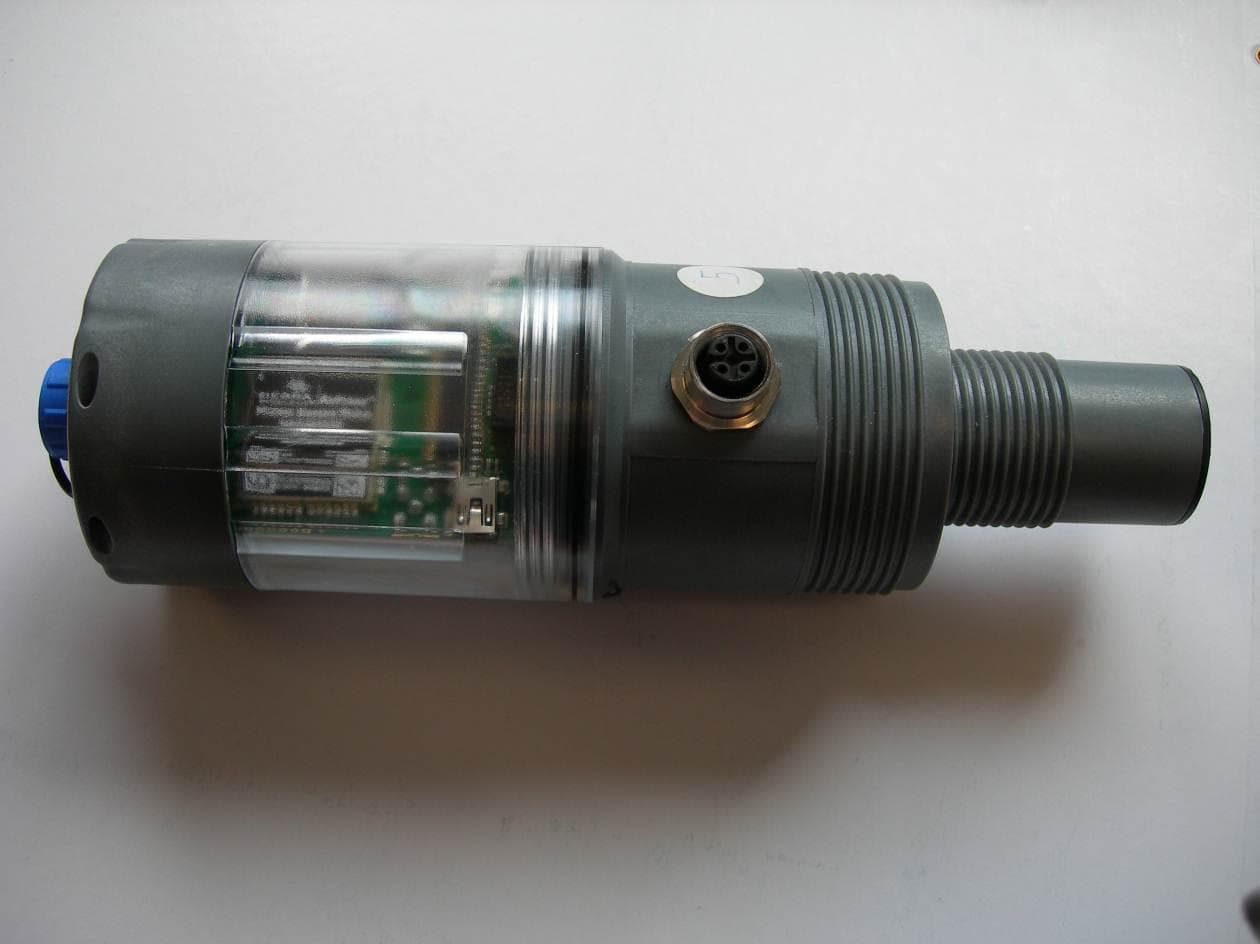
Click to zoom
Application Details
- Equipment Class
- DTS - Digital Transmission System
- Date of Grant
- Apr 29, 2013
- Application Purpose
- Original Equipment
- Date of Application
- Apr 29, 2013
- Equipment Note
- Wiji Wireless sensor/logger
- Frequency Range
- 915.00000000 - 915.00000000
- Company
- IJINUS
- Country
- France
Documents & Files
Document Text
Text extracted from the exhibit documents filed with the FCC. Open a document above to read the original.
Users Manual
UM001 User Manual Introduction This manual includes the most important information concerning the product of the Ijinus's product family called “L”. In this manual, are detailed : - installing information - mechanical characteristics - electrical characteristics - security points - prediagnostic elements 05/04/2013K0J00001-01A041/19 “A0101” products (“L” product familly) ContenuUM001 Contenu 1 Concerned products...............................................................................................................................3 2 Operating and safety instructions...........................................................................................................4 2.1 Operating instructions...................................................................................................................4 2.2 Safety instructions........................................................................................................................4 2.3 Warning to users in the United States..........................................................................................4 2.4 Warning to users in the Canada...................................................................................................5 3 Technical specifications..........................................................................................................................6 3.1 Main specifications.......................................................................................................................6 3.2 Mechanical speciations................................................................................................................9 3.3 Functionalities...............................................................................................................................9 3.4 Connectors and wiring..................................................................................................................9 4 Installation guide...................................................................................................................................10 4.1 Inserting the SIM card................................................................................................................10 4.2 Changing batteries.....................................................................................................................10 4.3 Mounting the sensor with our mounting plates...........................................................................11 5 Quick Troubleshooting .........................................................................................................................12 5.1 Meaning of the LED flashes .......................................................................................................12 5.2 Sensor update............................................................................................................................12 5.3 FAQ............................................................................................................................................13 6 Attached documents.............................................................................................................................14 6.1 Batteries recommended by IJINUS...........................................................................................14 6.2 Technical drawings.....................................................................................................................14 6.2.1 LNU0300/0600 :..........................................................................................................................14 6.2.2 LNU1000 :...................................................................................................................................15 6.2.3 LOG :..........................................................................................................................................16 7 Contact.................................................................................................................................................17 8 Document History.................................................................................................................................18 www.ijinus.com K0J00001-01A042/19 Concerned productsUM001 1 Concerned products The products concerned by this manual are the devices included in the « L » family. All these products are based on the same hardware basis and follows the same software updates. Many functionalities are common to all the products. Especially the radio ISM communication. www.ijinus.com K0J00001-01A043/19 Operating and safety instructionsUM001 2 Operating and safety instructions 2.1 Operating instructions •Check the presence of a desiccant pack after an opening when you close the housing. This pack must be replaced after a contact with ambient air longer than 3 minutes. •To ensure the most precise measurements, the sensor must be placed perpendicularly to the target area to measure. •Only the use of Ijinus' accessories ensures the the best and the more safely installation. •Do not handle the devices using the antenna. •Do not mechanically force the connectors. •Do not use tools to screw the connectors. They are designed to be hand screwed. •Take care of the wise of insertion of the SIM card. •Do not unscrew the transparent raising piece without have removed the gray cover. 2.2 Safety instructions •Do not shortcut, reload, pierce, warm, put into fire, crush the batteries •Do not shake the devices. •Do not physically modify the devices. •Do not clean the devices with aggressive products like acetone. •Do not use batteries not recommended by Ijinus (see battery references in attached documents) •The devices contain elements sensitive to electrostatic discharge. Download your body from electrostatic loads before opening and manipulate the devices by touching a metallic surface linked to the Earth. 2.3 Warning to users…
Text truncated - open the document above for the full version.
External Photos
IJINUS A0101 external photos FCC Id : SE6A001 IC : 10983A-A001
ID Label/Location Info
2013/03/20K0B00004-A01-A011/1 A0101 with GSM module – FCC/IC Label - 43x25mm 2013/03/20K0B00005-A01-A011/1 A0101 without GSM module – FCC/IC Label - 43x29mm IJINUS 25 ZA KERVIDANOU 3 29300 MELLAC France www.ijinus.com
Internal Photos
IJINUS A0101 internal photos FCC Id : SE6A001 IC : 10983A-A001 Motherboard Ultrasonic daughterboard GSM GPRS daughterboard Modbus daughterboard
RF Exposure Info
Product name:A0101 Manufacturer:IJINUS FCC Id:SE6A001 Prediction of MPE limit at a given distance Equation from page 18 of OET Bulletin 65, Edition 97-01 where:S = power density P = power input to the antenna G = power gain of the antenna in the direction of interest relative to an isotropic radiator R = distance to the center of radiation of the antenna Transmitter n°1 Maximum peak output power at the antenna terminal:12.00(dBm) Maximum peak output power at the antenna terminal:15.84893192(mW) Antenna gain(typical):0(dBi) Maximum antenna gain:1(numeric) Prediction distance:20(cm) Prediction frequency:915(MHz) MPE limit for uncontrolled exposure at prediction frequency:0.61(mW/cm^2) Power density at prediction frequency:0.003153(mW/cm^2) Maximum allowable antenna gain:22.8659969(dBi) Transmitter n°2 Maximum peak output power at the antenna terminal:32.31(dBm) Maximum peak output power at the antenna terminal:1702.158508(mW) Antenna gain(typical):1(dBi) Maximum antenna gain:1.258925412(numeric) Prediction distance:20(cm) Prediction frequency:850(MHz) MPE limit for uncontrolled exposure at prediction frequency:0.55(mW/cm^2) Power density at prediction frequency:0.426315(mW/cm^2) Maximum allowable antenna gain:2.106325448(dBi) Transmitter n°3 Maximum peak output power at the antenna terminal:29.35(dBm) Maximum peak output power at the antenna terminal:860.9937522(mW) Antenna gain(typical):1(dBi) Maximum antenna gain:1.258925412(numeric) Prediction distance:20(cm) Prediction frequency:1900(MHz) MPE limit for uncontrolled exposure at prediction frequency:1(mW/cm^2) Power density at prediction frequency:0.215640(mW/cm^2) Maximum allowable antenna gain:7.662698554(dBi) Collocation evaluation for the following cases: Pd(n) = Power density of n th transmitter at 20cm LPd(n)= Power density limit for the n th transmitter Transmitter n°1 + Transmitter n°2 : [Pd(1)/LPd(1)] + [Pd(2)/LPd(2)] =0.78029 <1 Transmitter n°1 + Transmitter n°3 : [Pd(1)/LPd(1)] + [Pd(3)/LPd(3)] =0.22081 <1 Note: Transmitter n°2 & transmitter n°3 can't transmit simultaneously 2 4R PG S p =
Test Report
TEST REPORT N°119778-639212 Page 2/37 SUMMARY 1. TEST PROGRAM ............................................................................................................................... 3 2. EQUIPMENT DESCRIPTION .............................................................................................................. 4 3. OCCUPIED BANDWIDTH ................................................................................................................... 6 4. -6DB BANDWIDTH ............................................................................................................................. 8 5. MAXIMUM PEAK CONDUCTED POWER ........................................................................................ 10 6. POWER SPECTRAL DENSITY ........................................................................................................ 12 7. BAND EDGE ..................................................................................................................................... 14 8. CONDUCTED SPURIOUS EMISSIONS ........................................................................................... 16 9. TRANSMITTER RADIATED EMISSIONS ......................................................................................... 18 10. RECEIVER RADIATED EMISSIONS ................................................................................................ 21 11. TEST EQUIPMENT LIST .................................................................................................................. 24 12. UNCERTAINTIES CHART ................................................................................................................ 25 13. ANNEX (GRAPHS) .......................................................................................................................... 26 TEST REPORT N°119778-639212 Page 3/37 1. TEST PROGRAM References Standards: - 47 CFR Part 15C - RSS-210 - RSS-Gen - RSS-102 - CISPR 16-4-2 - ANSI C63.4 Standard Section Test Description TEST RESULT - Comments RSS-Gen § 4.6.1 Occupied Bandwidth PASS CFR 47 § 15.247 (a) (2) RSS-210 § A8.2(a) -6dB Bandwidth PASS CFR 47 § 15.247 (b) RSS-210 § A8.4(4) Maximum Peak Output Power PASS CFR 47 § 15.247 (e) RSS-210 § A8.2 (b) Power Spectral Density PASS CFR 47 § 15.247 (d) RSS-210 § A8.5 Band Edge PASS CFR 47 § 15.247 (d) RSS-210 § A8.5 Conducted Spurious Emissions PASS CFR 47 § 15.207 RSS-Gen § 7.2.4 AC Power Line Conducted Emissions NA (Powered by internal battery) CFR 47 § 15.209 (a) CFR 47 § 15.247 (d) RSS-210 § A8.5 Transmitter Radiated emissions PASS RSS-Gen § 4.10 Receiver Radiated emissions PASS PASS: EUT complies with standard’s requirement FAIL: EUT does not comply with standard’s requirement NA: Not Applicable NP: Test Not Performed TEST REPORT N°119778-639212 Page 4/37 2. EQUIPMENT DESCRIPTION 2.1. HARDWARE IDENTIFICATION Equipment under test (EUT): Photograph of EUT Auxiliary equipment (AE) used for testing: - No Auxiliary equipment Input/output: - No input/output Equipment information: - External antenna connector: Yes - Frequency band allocated: 900MHz to 930MHz - Frequency band used: 915MHz - Modulation: GFSK - Number of channel: 1 - Antenna type: External - Spreading: No - Stand By mode: Yes (Receiver mode) - Maximum Antenna Gain: 0dBi - Type of power source: Battery (Lithium 2*3,6Vdc) - Power supply: 3,6Vdc - Frequency plan: Channel Frequency (MHz) Fnom 915 Equipment of the same family: (See Technical Description for details) The equipment consists of 1 motherboard(MB) + 2 optional daughterboards(DB). Motherboard MB supports 915MHz RF function. Optional daughterboard may be “Ultrasonic DB”, “GSM DB” or “ModBus DB”. Tests have been performed on the worst case configuration model IJINUS A0101 defined during prescan tests. This worst configuration which test results are described in this report is 1 motherboard MB + 1 GMS DB + 1 US DB. TEST REPORT N°119778-639212 Page 5/37 2.2. RUNNING MODE The EUT is set in the following modes during tests: -Permanent emission with modulation -Communication -Permanent reception 2.3. EQUIPEMENT LABELLING 2.4. EQUIPMENT MODIFICATIONS No equipment modification has been necessary during testing. TEST REPORT N°119778-639212 Page 6/37 3. OCCUPIED BANDWIDTH 3.1. TEST CONDITIONS Test performed by : Stéphane PHOUDIAH Date of test : 2013/03/28 Ambient temperature : 22°C Relative humidity : 41% 3.2. TEST SETUP The Equipment Under Test is installed on a table and set in permanent emission with modulation. Measurement is performed with a spectrum analyzer on the EUT conducted access. The product has been tested according to the RSS- GEN § 4.6.1 reference method. Spectrum Analyzer Setting: Center frequency=Fnom Span= At least twice the emission spectrum Amplitude= Sufficient to observe the signal amplitude RBW= 1% of span VBW= 3*RBW Sweep= Auto Trace= Max Hold Detector= Peak Occupied Bandwidth 99% activated Photograph for Occupied Bandwidth TEST REPORT N°119778-639212 Page 7/37 3.3. RESULTS Temperature Tnom Voltage Vnom Frequency Fnom Occupied Bandwidth (kHz) 598,8 See graphics in annex Result: PASS Limit: None TEST REPORT N°119778-639212 Page 8/37 4. -6DB BANDWIDTH 4.1. TEST CONDITIONS Test performed by : Stéphane PHOUDIAH Date of test : 2013/03/28 Ambient temperature : 22°C Relative humidity : 41% 4.2. TEST SETUP The Equipment Under Test is installed on a table and set in permanent emission with modulation. Measurement is performed with a spectrum analyzer on the EUT conducted access. The product has been tested according to the FCC KDB 558074 D01 DTS Meas Guidance v02 § 7.1. Spectrum Analyzer Setting: Center frequency= Fnom Span= At least twice the emission spectrum Amplitude= Sufficient to observe the signal amplitude RBW= 100kHz VBW= 300kHz Sweep= Auto Trace= Max Hold Detector= Peak Photograph for Bandwidth TEST REPORT N°119778-639212 Page 9/37 4.3. RESULTS Temperature Tnom Voltage Vnom Frequency Fnom -6dB Bandwidth (kHz) 534,4 See graphics in…
Text truncated - open the document above for the full version.
Test Setup Photos
FCC ID: SE6A001 IC: 10983A-A001 TEST SET UP PHOTOS IJINUS A0101 Radiated emissions measurements FCC ID: SE6A001 IC: 10983A-A001 Radiated emissions measurements FCC ID: SE6A001 IC: 10983A-A001 Radio test measurements
Contact Information
Applicant
Olivier LE STRAT(Chief Executive Officer)
Test Firm
LCIEPatrick Pereira Teixeira
Technical Specifications
| # | Rule Parts | Frequency Range | Power Output |
|---|---|---|---|
| 1 | 15C | 915 MHz - 915 MHz | 12.00 mW |
Other Applications from IJINUS
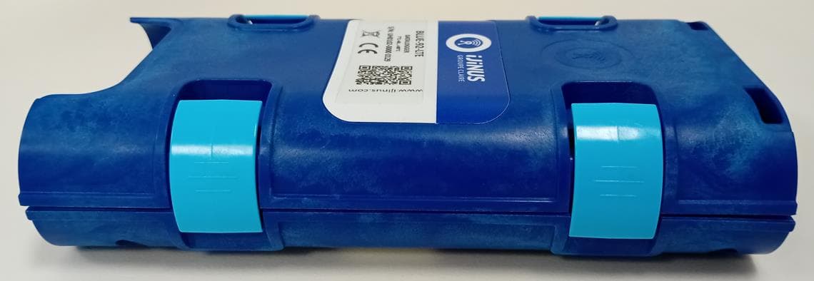
SE6H001
Jul 07, 2024DATALOGGER & PRESSURE RECORDER
Equipment Class
DTS - Digital Transmission System
SE6B001
Aug 30, 2020ACCESS POINT 915MHz (US) / LAN
Equipment Class
DTS - Digital Transmission System
SE6E004
Jan 08, 2020TEMPERATURE DATA LOGGER LT2
Equipment Class
DTS - Digital Transmission System
SE6E003
Jan 08, 2020TEMPERATURE DATA LOGGER LT7
Equipment Class
DTS - Digital Transmission System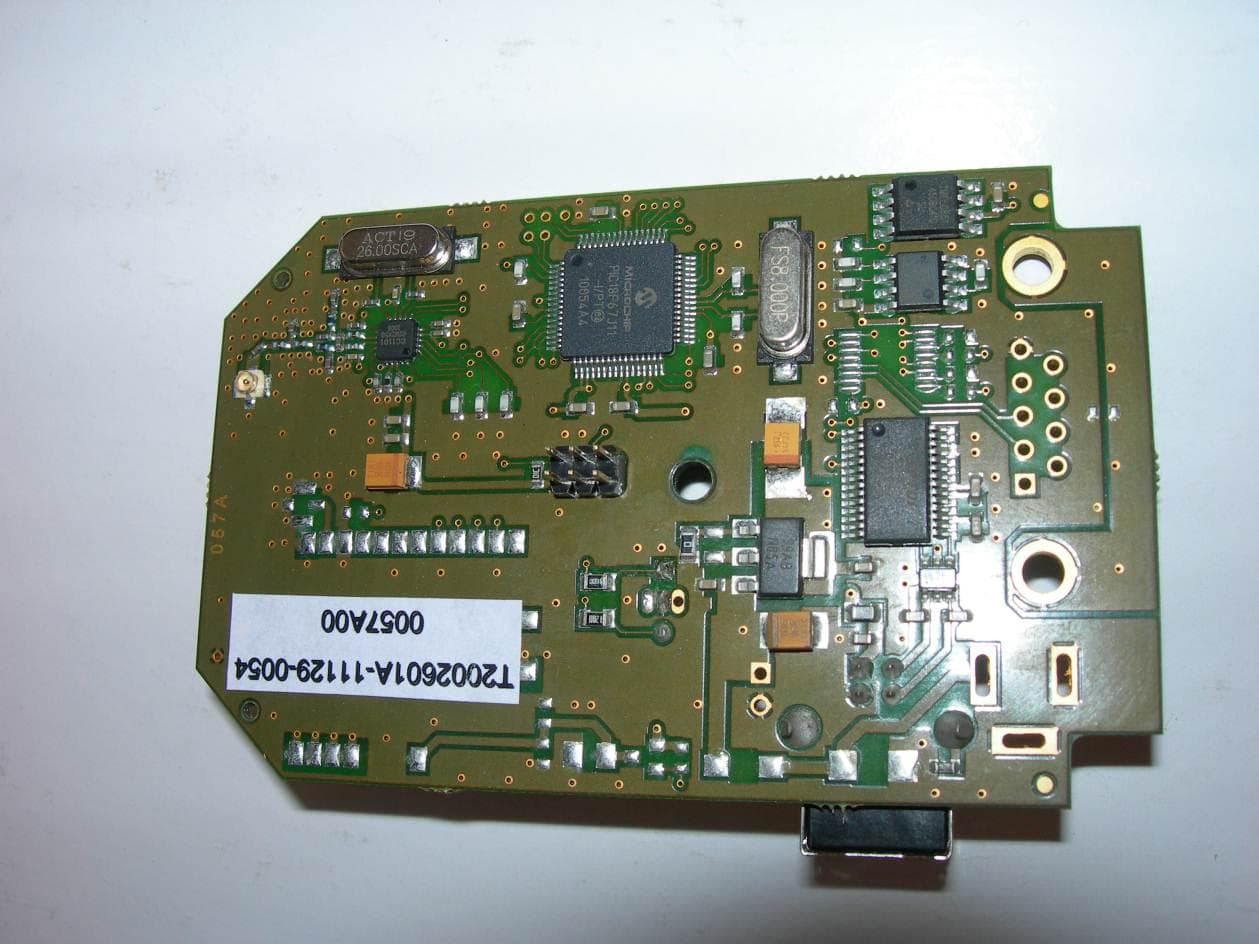
SE6E001
May 13, 2013Access Point
Equipment Class
DTS - Digital Transmission System