SEKMC56Dual-Band GSM Mobile Transmitter Module
Ingenico Belgium SRL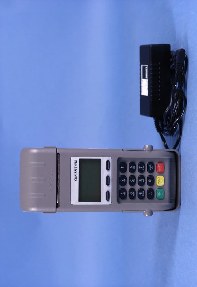
Click to zoom
Application Details
- Equipment Class
- PCB - PCS Licensed Transmitter
- Date of Grant
- Jul 30, 2006
- Application Purpose
- Original Equipment
- Date of Application
- Jul 30, 2006
- Equipment Note
- Dual-Band GSM Mobile Transmitter Module
- Frequency Range
- 1850.20000000 - 1909.80000000
- Company
- Ingenico Belgium SRL
- Country
- Belgium
Documents & Files
Document Text
Text extracted from the exhibit documents filed with the FCC. Open a document above to read the original.
Users Manual
MC55/56 Hardware Interface Description Confidential / Preliminary s MC55/56_hd_v03.00 Page 1 of 104 16.08.2005 Hardware Interface Descri p tion MC55/56 Siemens Cellular Engine Version: 03.00 DocID: MC55/56_hd_v03.00 MC55/56 Hardware Interface Description Confidential / Preliminary s MC55/56_hd_v03.00 Page 2 of 104 16.08.2005 Document Name: MC55/56 Hardware Interface Description Version: 03.00 Date: August 16, 2005 DocId: MC55/56_hd_v03.00 Status: Confidential / Preliminary General Notes Product is deemed accepted by Recipient and is provided without interface to Recipient’s products. The documentation and/or Product are provided for testing, evaluation, integration and information purposes. The documentation and/or Product are provided on an “as is” basis only and may contain deficiencies or inadequacies. The Documentation and/or Product are provided without warranty of any kind, express or implied. To the maximum extent permitted by applicable law, Siemens further disclaims all warranties, including without limitation any implied warranties of merchantability, completeness, fitness for a particular purpose and non-infringement of third-party rights. The entire risk arising out of the use or performance of the Product and documentation remains with Recipient. This Product is not intended for use in life support appliances, devices or systems where a malfunction of the product can reasonably be expected to result in personal injury. Applications incorporating the described product must be designed to be in accordance with the technical specifications provided in these guidelines. Failure to comply with any of the required procedures can result in malfunctions or serious discrepancies in results. Furthermore, all safety instructions regarding the use of mobile technical systems, including GSM products, which also apply to cellular phones must be followed. Siemens or its suppliers shall, regardless of any legal theory upon which the claim is based, not be liable for any consequential, incidental, direct, indirect, punitive or other damages whatsoever (including, without limitation, damages for loss of business profits, business interruption, loss of business information or data, or other pecuniary loss) arising out the use of or inability to use the Documentation and/or Product, even if Siemens has been advised of the possibility of such damages. The foregoing limitations of liability shall not apply in case of mandatory liability, e.g. under the German Product Liability Act, in case of intent, gross negligence, injury of life, body or health, or breach of a condition which goes to the root of the contract. However, Claims for Damages arising from a breach of a condition which goes to the root of the contract shall be limited to the foreseeable damage which is intrinsic to the contract, unless caused by intent or gross negligence or based on liability for injury of life, body or health. The above provision does not imply a change on the burden of proof to the detriment of the Recipient. Subject to change without notice at any time. The interpretation of this general note shall be governed and construed according to German law without reference to any other substantive law. Copyright Copying of this document and giving it to others and the use or communication of the contents thereof, are forbidden without express authority. Offenders are liable to the payment of damages. All rights reserved in the event of grant of a patent or the registration of a utility model or design. Copyright © Siemens AG 2005 MC55/56 Hardware Interface Description Confidential / Preliminary s MC55/56_hd_v03.00 Page 3 of 104 16.08.2005 Contents 0 Document history..........................................................................................................7 1 Introduction ...................................................................................................................9 1.1 Related documents ................................................................................................9 1.2 Terms and abbreviations .....................................................................................10 1.3 Type approval ......................................................................................................13 1.4 Safety precautions ...............................................................................................15 2 Product concept..........................................................................................................17 2.1 MC55/56 key features at a glance .......................................................................18 2.2 Circuit concept .....................................................................................................21 3 Application Interface...................................................................................................22 3.1 Operating modes .................................................................................................23 3.2 Power supply .......................................................................................................25 3.2.1 Power supply pins on the board-to-board connector .............................25 3.2.2 Minimizing power losses ........................................................................26 3.2.3 Monitoring power supply ........................................................................26 3.3 Power up / down scenarios..................................................................................27 3.3.1 Turn on MC55/56 ...................................................................................27 3.3.1.1 Turn on MC55/56 using the ignition line /IGT (Power on)......................28 3.3.1.2 Timing of the ignition process ................................................................29 3.3.1.3 Turn on MC55/56 using the POWER signal ..........................................30 3.3.1.4 Turn on MC55/56 using the RTC (Alarm…
Text truncated - open the document above for the full version.
Users Manual
Legal disclaimer and copyrights The information in this guide is subject to change without notice. BANKSYS SHALL NOT BE LIABLE FOR TECHNICAL OR EDITORIAL ERRORS OR OMISSIONS CONTAINED HEREIN; NOR FOR INCIDENTAL OR CONSEQUENTIAL DAMAGES RESULTING FROM THE DELIVERY, PERFORMANCE, OR USE OF THIS MATERIAL. NOTHING IN THIS GUIDE SHALL BE CONSTRUED OR INTERPRETED AS AN IMPLIED OBLIGATION ON BANKSYS UNLESS CLEARLY STATED OTHERWISE. REPRODUCTION IN ANY MANNER WHATSOEVER WITHOUT THE WRITTEN PERMISSION OF BANKSYS IS STRICTLY FORBIDDEN. TRADEMARKS USED IN THIS TEXT: C-ZAM/XENTA, C-ZAM/SMASH, THE BANKSYS LOGO, AND LATITUDE ARE TRADEMARKS OF BANKSYS. BANKSYS DISCLAIMS ANY PROPRIETARY INTEREST OR RESPONSIBILITY IN TRADEMARKS AND TRADE NAMES OTHER THAN ITS OWN. ALL PRIVATE OR PRIVACY RELATED INFORMATION AND ALL CORPORATE PROTECTED INFORMATION OR COMPETITIVE SENSITIVE INFORMATION IN THIS TEXT SHOULD BE DULY KEPT CONFIDENTIAL. ALL RIGHTS RESERVED. Product Guide C-ZAM/XENTA Released version 1.0 © Banksys, June 2, 2004 C-ZAM/XENTA PRODUCT GUIDE Table of contents INTRODUCTION ...............................................................................................................3 LIST OF ACRONYMS.......................................................................................................4 GENERAL DESCRIPTION..............................................................................................5 TECHNICAL SPECIFICATIONS.................................................................................7 DIMENSIONS (MM) AND WEIGHT (G).......................................................................7 KEYPAD....................................................................................................................................7 DISPLAY...................................................................................................................................9 CARD INTERFACES...............................................................................................................9 .............................................................................................10 CHIP SECURITY MODULES .........................................................................................................11 THE SAMOA ASIC ..........................................................................................................................11 INTERFACES ................................................................................................................................. 12 OTHERS ...............................................................................................................12 POWER ADAPTER ENVIRONMENTAL SPECIFICATIONS...........................................................................13 APPROVALS..........................................................................................................................13 SECURITY..............................................................................................................................14 SAMOA ASIC...................................................................................................................14 SECURE TERMINAL DESIGN...........................................................................................14 SECURITY SOFTWARE.......................................................................................................15 .........................................................................................................................15 STANDARDS .....................................................................................................................16 ACCESSORIES ADDITIONAL INTERFACE BOARDS.............................................................................16 General description................................................................................................16 Technical specifications.......................................................................................16 ISDN interface board.........................................................................................................16 .................................................................................17 GSM / GPRS / SMS interface board USB interface board...........................................................................................................17 ...................................................................................................................................17 Others ................................................................................................................................. 18 PRINTER General description................................................................................................18 Version: 1.0 1 C-ZAM/XENTA PRODUCT GUIDE Technical specifications.......................................................................................18 Dimensions (mm) and weight...........................................................................................18 Printer specifications and approvals................................................................................18 .....................................................................................................................................19 Paper Environmental conditions..................................................................................................19 MERCHANT UNIT..............................................................................................................20 General description................................................................................................20 Technical specifications.......................................................................................21 Dimensions (mm) and weight .............................................................................................................21 ...................................…
Text truncated - open the document above for the full version.
Users Manual
Legal disclaimer and copyrights The information in this document is subject to change without notice and shall not be construed as a commitment by Banksys S.A./N.V. The content of this document, including but not limited to trademarks, designs, logos, text, images, is the property of Banksys S.A/N.V. and is protected by the Belgian Act of 30.06.1994 related to author’s right and by the other applicable Acts. XENTISSIMO, XENTA, the Banksys logo, and latitude are trademarks of Banksys. Linux is a registered trademark of Linus Torvalds, Java is a registered trademark of Sun Microsystems Inc. and ARM is a registered trademark of ARM Limited. The contents of this document can be reproduced by or on behalf of third parties with the prior written consent of Banksys S.A./N.V and following its instructions. Except with respect to the limited license to download and print certain material from this document for non-commercial and personal use only, nothing contained in this document shall grant any license or right to use any of Banksys S.A./N.V.’s proprietary material. While Banksys S.A./N.V. has made every attempt to ensure that the information contained in this document is correct, Banksys S.A./N.V. does not provide any legal of commercial warranty on the document that is described in this specification. The technology is thus provided “as is” without warranties of any kind, expressed or implied, included those of merchantability and fitness for a particular purpose. Banksys S.A./N.V. does not warrant or assume any legal liability or responsibility for the accuracy, completeness, or usefulness of any information, product or processes disclosed. To the fullest extend permitted under applicable law, neither Banksys S.A./N.V. nor its affiliates, directors, employees and agents shall be liable to any party for any damages that might result from the use of the technology as described in this document (including without limitation direct, indirect, incidental, special, consequential and punitive damages, lost profits). These terms shall be governed by and construed in accordance with the laws of Belgium. You irrevocably consent to the jurisdiction of the courts located in Brussels for any action arising from or related to the use of this document. Product Manual XENTISSIMO Version 1.0 © Banksys, May 2006 XENTISSIMO PRODUCT MANUAL Table of contents Introduction.........................................................................9 List of acronyms.................................................................11 General description............................................................13 Technical specifications.....................................................15 Dimensions and weight...................................................15 Keypad............................................................................15 Display............................................................................17 Card interfaces.................................................................18 PIN privacy shield...........................................................19 Printer..............................................................................19 Wireless communication.................................................20 Interfaces.........................................................................24 Chip Security Modules.....................................................25 Banksys’ designed “System-on-Chip”...............................26 Power supply...................................................................26 Appearance.....................................................................28 Environmental conditions................................................29 Approvals........................................................................29 Good to know.................................................................30 Security..............................................................................33 The “System-on-Chip”.....................................................33 Terminal design...............................................................33 Security software.............................................................34 Standards.........................................................................34 Accessories.........................................................................35 Belt clip and fixation points.............................................35 Cradle..............................................................................36 Product identification.........................................................39 XENTISSIMO terminal.....................................................39 5 XENTISSIMO PRODUCT MANUAL XENTISSIMO cradle........................................................40 Terminal package box.....................................................41 Cradle package box........................................................41 Product package................................................................43 XENTISSIMO terminal.....................................................43 XENTISSIMO cradle........................................................44 Bulk packages.................................................................45 Development environment................................................49 6 XENTISSIMO PRODUCT MANUAL Table of figures Figure 1 – Terminal dimensions.........................................................................15 Figure 2 – Keypad..............................................................................................16 Figure 3 – Display..............................................................................................17 Figure 4 – Card interfaces..................................................................................18 Figure 5 – PIN privacy shield.............................................................................19 Figure 6 – Printer..…
Text truncated - open the document above for the full version.
Attestation Statements
July 27, 2006 CONFIDENTIALITY REQUEST Federal Communications Commission Authorization and Evaluation Division 7435 Oakland Mills Road Columbia, MD 21046 Re:Banksys application for GSM module to be used in point of sales terminals. FCC ID: SEKMC56 Gentlemen: Banksys requests, pursuant to 47CFR 0.459, post grant confidentiality for portions of the material contained in this application such that the identified material will be withheld from public inspection following the grant of this authorization. This material, as indicated by request for confidentiality of the item during the electronic submission process and further identified below, includes: 1. Schematic or circuit diagrams. 2. Block diagram 3. Operational description 4. Parts List Specifically, these exhibits contains information relating to circuit function and complexity that could be of benefit to competitors. The material contains trade secrets and confidential information that Banksys does not customarily release to the public and which is otherwise not generally available to the public. Please contact the undersigned by phone at 410-531-3439, by fax at 410-531-0807, by email at [email protected], or by correspondence at the address below if there are any further questions or additional information needed concerning this filing. Regards, (signed) Phillip Inglis, TRP/Cetecom bvba 14085 Howard Rd. Dayton, MD. 21036
Cover Letter(s)
. . . . . . . . . . . . . . . . . . . . . . . . . . . . . . . . . . . . . TRP Inc. July 27, 2006 Federal Communications Commission 7435 Oakland Mills Rd Columbia MD 21045 Gentlemen: Submitted herewith is a request for certification of a GSM module, FCC ID: SEKMC56 that will be used in hand held point of transaction banking terminals, Models Xenta, and Xentissimo. These modules are identical to Siemens AG model MC56, FCC ID: QIPMC56. Banksys purchases the module from Siemens and installs and antenna. Two antennas are provided, a low gain antenna (-2 dBi) and a higher gain antenna nominal gain (0dBi). These units were evaluated at PCTest Laboratory for compliance. Test reports as appropriate are submitted with the filing. According to published FCC policy, this type of device is subject to mobile requirements for RF exposure since it is intended to only be used in a hand held device (Xentissimo) or in a desk top device (Xenta). If you have any questions, please call Phillip Inglis at 410 531 3439 or contact via email at [email protected]. It is also requested that you forward copies of any correspondence and authorization documents to the email address specified above. Sincerely, Phillip Inglis Consultant 14085 Howard Rd Dayton, MD 21936
External Photos
BANKSYS FCC ID: SEKMC56 EUT Photographs © 2006 PCTEST Lab. Dual-Band GSM Mobile Transmitter Module NVLAP Lab Code: 100431-0 BANKSYS FCC ID: SEKMC56 EUT Photographs © 2006 PCTEST Lab. Dual-Band GSM Mobile Transmitter Module NVLAP Lab Code: 100431-0
ID Label/Location Info
This label will be placed on the module: The following label will be placed on the Xenta and Xentissimo units: The above label location will be on the bottom of the units as shown below: Bottom of unit Label Location Banksys Xenta FCC ID: SEKMC56 IC: 5264A-MC56 This unit contains the following Transmitter: FCC ID: SEKMC56 IC: 5264A-MC56
Internal Photos
BANKSYS FCC ID: SEKMC56 EUT Photographs © 2006 PCTEST Lab. Dual-Band GSM Mobile Transmitter Module NVLAP Lab Code: 100431-0 BANKSYS FCC ID: SEKMC56 EUT Photographs © 2006 PCTEST Lab. Dual-Band GSM Mobile Transmitter Module NVLAP Lab Code: 100431-0 BANKSYS FCC ID: SEKMC56 EUT Photographs © 2006 PCTEST Lab. Dual-Band GSM Mobile Transmitter Module NVLAP Lab Code: 100431-0 BANKSYS FCC ID: SEKMC56 EUT Photographs © 2006 PCTEST Lab. Dual-Band GSM Mobile Transmitter Module NVLAP Lab Code: 100431-0
RF Exposure Info
Prediction of MPE limit at given distance Equation from page 18 of OET Bulletin 65, Edition 97-01 where: S = power density P = power input to the antenna G = power gain of the antenna in the direction of interest relative to an isotropic radiator R = distance to the center of radiation of the antenna The table below is excerpted from Table 1B of 47 CFR 1.1310 titled Limits for Maximum Permissible Exposure (MPE), Limits for General Population/Uncontrolled Exposure: Frequency Range (MHz) Power Density (mW/cm 2 ) Averaging Time (minutes) 300 – 1500f/150030 1500 – 100.0001.030 where f = frequency in MHz Prediction GSM 1900 Antenna Type: 0dBi Antenna Maximum peak output power at antenna input terminal:28,70dBm Maximum peak output power at antenna input terminal:741,31mW Antenna gain(typical): 0,00dBi Maximum antenna gain: 1,00numeric Prediction distance: 20,00cm Prediction frequency: 1.880,00MHz MPE limit for uncontrolled exposure at prediction frequency:1.00 Power density at prediction frequency:0.147 with Antenna Gain of 0dBi Power density at prediction frequency:0,294 with Antenna Gain of 3dBi Power density at prediction frequency:0,587 with Antenna Gain of 6dBi Power density at prediction frequency:9 with Antenna Gain of 7dBi Maximum allowable antenna gain for GSM 1900 operations:8,31dBi 2 4R PG S π = 2 cm mW 2 cm mW 2 cm mW 2 cm mW Prediction GSM 850 Antenna Type: 0dBi Antenna / 7 dBi Antenna Maximum peak output power at antenna input terminal:33,00dBm Maximum peak output power at antenna input terminal:1.995,26mW Antenna gain(typical): 0,00dBi Maximum antenna gain: 1,00numeric Prediction distance: 20,00cm Prediction frequency: 836,40MHz MPE limit for uncontrolled exposure at prediction frequency:0,5576 Power density at prediction frequency:0.397 with Antenna Gain of 0dBi Power density at prediction frequency:0,792 with Antenna Gain of 3dBi Power density at prediction frequency:1,580 with Antenna Gain of 6dBi Power density at prediction frequency:1,989 with Antenna Gain of 7dBi Maximum allowable antenna gain for GSM 1900 operations:1,48dBi 2 cm mW 2 cm mW 2 cm mW 2 cm mW 2 cm mW
Test Report
CETECOM ICT Services GmbH Radio Satellite Communication Untertürkheimer Straße 6-10 . D-66117 SaarbrückenTelefon: +49 (0)681 598-9100Telefax: -9075 RSC11Issued test report consists of 97 pagesPage 1 (97) BLUETOOTH TM is a trademark owned by Bluetooth SIG, Inc. and licensed to CETECOM Recognized by the Federal Communications Commission Anechoic chamber registration no.: 90462 (FCC) Anechoic chamber registration no.: 3463 (IC) TCB ID: DE 0001 Accredited by the German Accreditation Council DAR–Registration Number TTI–P–G 166/98 Independent ETSI compliance test house ETSI Accredited Bluetooth™ Test Facility (BQTF) Test report no.: 2_3450-01-01/03 FCC Part 24/22/15 MC56 FCC ID: QIPMC56 IC: 267W-MC56 CETECOM – ICT Services GmbH Untertürkheimerstr. 6-10 66117 Saarbrücken, Germany Telephone: + 49 (0) 681 / 598-0 Fax: + 49 (0) 681 / 598-9075 CETECOM ICT Services GmbH Test report no..: 2_3450-01-01/03Issue Date: 2003-12-12Page 2 (97) Table of Contents 1 General information 1.1 Notes 1.2 Testing laboratory 1.3 Details of applicant 1.4 Application details 1.5 Test item 1.6 Test standards 2 Technical test 2.1 Summary of test results 2.2 Test report 1 General information 1.1 Notes The test results of this test report relate exclusively to the test item specified in 1.5. The CETECOM ICT Services GmbH does not assume responsibility for any conclusions and generalizations drawn from the test results with regard to other specimens or samples of the type of the equipment represented by the test item. The test report may only be reproduced or published in full. Reproduction or publication of extracts from the report requires the prior written approval of the CETECOM ICT Services GmbH. 1.2Testing laboratory CETECOM ICT Services GmbH Untertürkheimer Straße 6 - 10 66117 Saarbrücken Germany Telefone: + 49 681 598 - 9100 Telefax : + 49 681 598 - 9075 E-mail: [email protected] Internet: www.cetecom-ict.de Accredited testing laboratory The test laboratory (area of testing) is accredited according to DIN EN ISO/IEC 17025. DAR registration number: TTI-P-G-166/98 Listed by: Federal Communications Commission (FCC) Identification/Registration No : 90462 Accredited Bluetooth TM Test Facility (BQTF) BLUETOOTH TM is a trademark owned by Bluetooth SIG, Inc. and licensed to CETECOM CETECOM ICT Services GmbH Test report no..: 2_3450-01-01/03Issue Date: 2003-12-12Page 3 (97) 1.3Details of applicant Name : Siemens AG Street : Siemensdamm 50 City : D-13629 Berlin Country : Germany Telephone : +49 (0)30 386-0 Telefax : +49 (0)30 386-366-56 Contact : Mr. Hussein Halawi Telephone : +49 (0)30 386-302-11 e-mail: [email protected] 1.4Application details Date of receipt of application : 2003-12-03 Date of receipt of test item : 2003-12-03 Date of test : 2003-12-03 1.5Test item Type of equipment : Tripple Band GSM/PCS Module (850/1800/1900 MHz) Type designation:MC56 Manufacturer:applicant Street: City: Country: Serial numbers:IMEI :004999.00.273656.01, Ser Nr. 273056 Additional information: : Frequency:1850.2 – 1909.8 MHz and 824.2 – 848.8 MHz Type of modulation:300KGXW / 300KG7W Number of channels :300 (PCS1900) and 125 (PCS850) Antenna:Coax adapter for use with external antennas, here a standard car magnet antenna Power supply:3,8V DC via connector Output power GSM 850:cond.: 33.0 dBm Peak , ERP: 24.8 dBm (Burst); EIRP: 26.9 dBm (Burst) Output power GSM 1900 :cond : 28.7 dBm Peak , ERP: 25.3 dBm (Burst); EIRP: 27.4 dBm (Burst) Type of equipment:Temperature range : -30°C - +60°C FCC – ID:QIPMC56 IC :267W-MC56 Hardware:S30880-S8365-A100(B1) Software:026 1.6Test standards: FCC Part 24, 22 FCC Part 15 CETECOM ICT Services GmbH Test report no..: 2_3450-01-01/03Issue Date: 2003-12-12Page 4 (97) 2 Technical test For Part 24/22 we use the substitution method ( TIA/EIA 603). All measurements in this report are done in GSM mode. Device is able to transmit data in GPRS mode also. But because the current measurements are performed in PEAK mode no other results from GPRS mode are possible. The only different is the modulation average power, which is 3 dB higher (by using 2 timeslots in the Up-link (GPRS mode 10)). Remarks: Test setup :The sample was tested in a special test board to bring power to the card and connect RF over a special coax connector to a standard coax adapter. For radiated measurements we used a standard magnetic dualband mobile antenna mounted on a metal plate to get comparative results. No deviations from the technical specification(s) were ascertained in the course of the tests performed. FINAL VERDICT: PASS Technical responsibility for area of testing : 2003-12-15RSC 8414 Ames H. DateSectionNameSignature Technical responsibility for area of testing : 2003-12-15RSC8412Hausknecht D. DateSectionNameSignature CETECOM ICT Services GmbH Test report no..: 2_3450-01-01/03Issue Date: 2003-12-12Page 5 (97) 2.2Test report TEST REPORT Test report no. : 2_3450-01-01/03 CETECOM ICT Services GmbH Test report no..: 2_3450-01-01/03Issue Date: 2003-12-12Page 6 (97) TEST REPORT REFERENCE LIST OF MEASUREMENTS PARAMETER TO BE MEASURED PAGE Part PCS 1900 POWER OUTPUT SUBCLAUSE § 24.2328 FREQUENCY STABILITY SUBCLAUSE § 24.23510 AFC FREQ ERROR vs. VOLTAGE11 AFC FREQ ERROR vs. TEMPERATURE11 EMISSIONS LIMITS SUBCLAUSE §24.23813 RECEIVER SPURIOUS RADIATION SUBCLAUSE § 15.10922 CONDUCTED SPURIOUS EMISSIONS27 BLOCK EDGE COMPLIANCE FOR BLOCK A AND C36 OCCUPIED BANDWIDTH SUBCLAUSE §2.98938 PART PCS 850 POWER OUTPUT SUBCLAUSE § 22.91345 FREQUENCY STABILITY SUBCLAUSE § 22.35547 AFC FREQ ERROR vs. VOLTAGE48 AFC FREQ ERROR vs. TEMPERATURE48 EMISSIONS LIMITS SUBCLAUSE §22.91750 RECEIVER SPURIOUS RADIATION SUBCLAUSE § 15.10959 CONDUCTED SPURIOUS EMISSIONS63 BLOCK EDGE REQUIREMENTS72 OCCUPIED BANDWIDTH SUBCLAUSE §2.98974 EMISSION LIMITATIONS FOR CELLULAR SUBCLAUSE §22.917(F)81 CETECOM ICT Services GmbH Test report no..: 2_3450-01-01/03Issue Date: 2003-12-12Page 7 (97) TEST EQUIPMENT AND ANCILLARIES USED FOR TESTS90 Test site92 CETECOM ICT Services Gmb…
Text truncated - open the document above for the full version.
Test Report
Reviewed by: PCTEST™ PT. 22/24 GSM TEST REPORT FCC MEASUREMENT REPORT (GSM) Quality Manager Test Report S/N: Test Dates: EUT Type: 0606200530 July 10 - J…
Text truncated - open the document above for the full version.
Contact Information
Applicant
Denis Verheyden(Certification responsible)
Technical Contact
PCTEST Engineering Lab., Inc.Randy Ortanez
[email protected]410-290-6652
6660-B Dobbin Road · Columbia, Maryland · United States
Test Firm
PCTEST Engineering Laboratory, Inc.Randy Ortanez
Technical Specifications
| # | Rule Parts | Frequency Range | Power Output | Emission | Tolerance |
|---|---|---|---|---|---|
| 2 | 24E | 1.85 GHz - 1.91 GHz | 741.00 mW | 300KGXW | 2.5 ppm |
Other Applications from Ingenico Belgium SRL
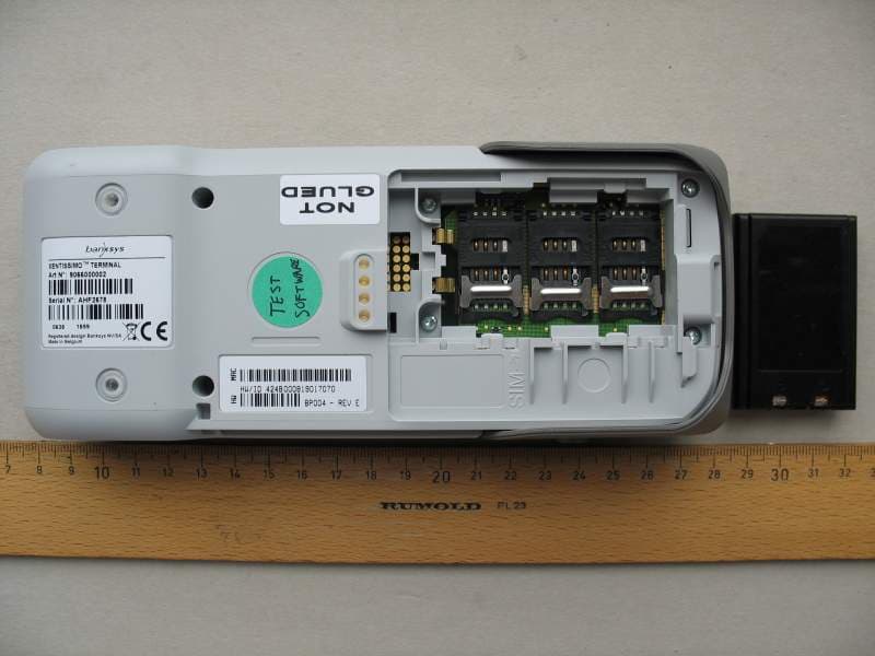
SEKXIBGW200
Dec 20, 2007Handheld POS Terminal
Equipment Class
DTS - Digital Transmission System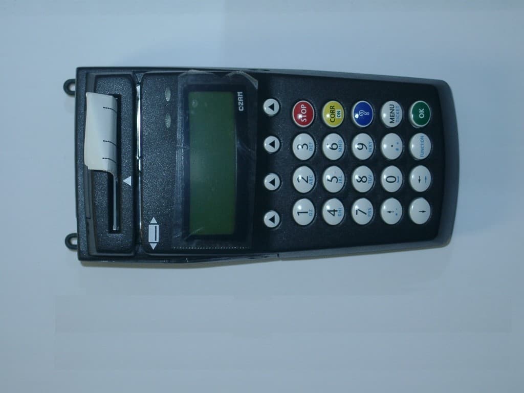
SEK41377S1
Dec 04, 2005Point of sale payment terminal
Equipment Class
DSS - Part 15 Spread Spectrum Transmitter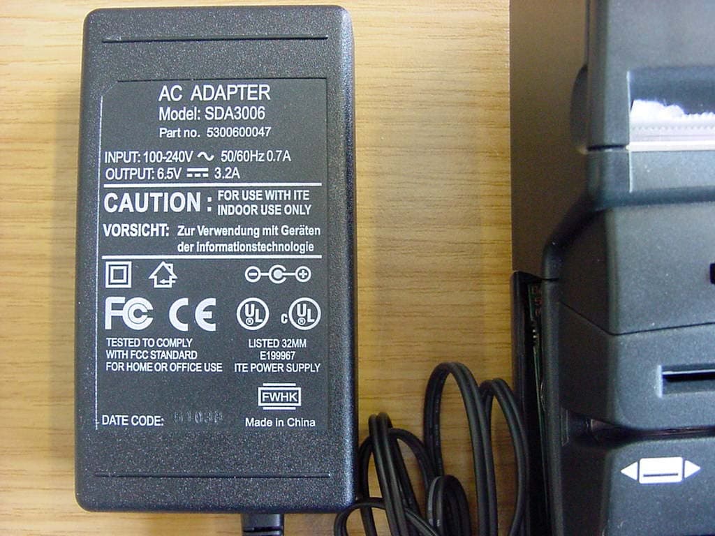
SEKGR48
Aug 07, 2004Hand held portable terminal
Equipment Class
PCB - PCS Licensed Transmitter