SEKXIBGW200Handheld POS Terminal
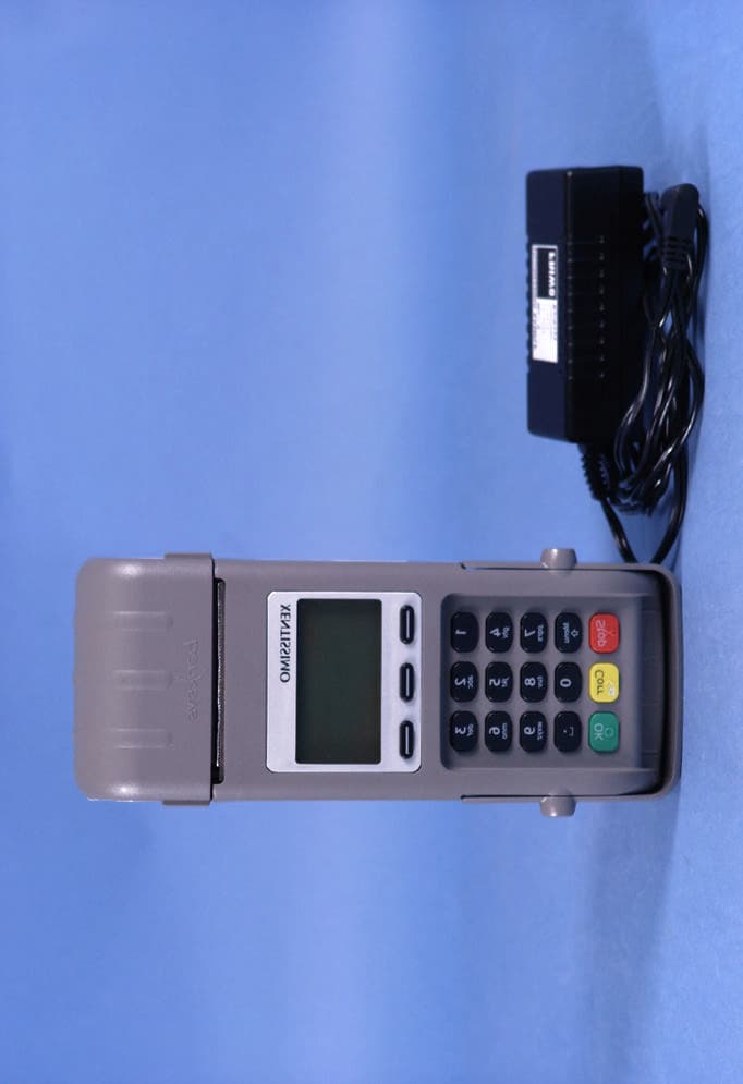
Ingenico Belgium SRL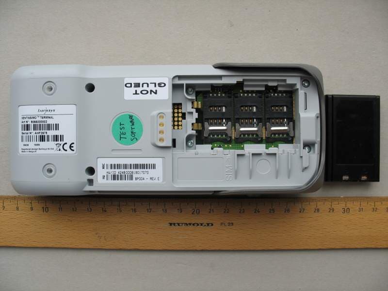
Click to zoom
Application Details
- Equipment Class
- DTS - Digital Transmission System
- Date of Grant
- Dec 20, 2007
- Application Purpose
- Original Equipment
- Date of Application
- Dec 20, 2007
- Equipment Note
- Handheld POS Terminal
- Frequency Range
- 2412.00000000 - 2462.00000000
- Company
- Ingenico Belgium SRL
- Country
- Belgium
Documents & Files
Document Text
Text extracted from the exhibit documents filed with the FCC. Open a document above to read the original.
Users Manual
Author Verheyden Dept. T&P/PRD Created 20/11/2007 10:22 FCC notices for XENTISSIMO User’s Manual y Rev. Saved: FCC notice1.doc 1.1 28/11/2007 14:47 Page 1 of 1 FCC rules: 15.105 NOTE: This equipment has been tested and found to comply with the limits for a Class B digital device, pursuant to Part 15 of the FCC Rules. These limits are designed to provide reasonable protection against harmful interference in a residential installation. This equipment generates, uses and can radiate radio frequency energy and, if not installed and used in accordance with the instructions, may cause harmful interference to radio communications. However, there is no guarantee that interference will not occur in a particular installation. If this equipment does cause harmful interference to radio or television reception, which can be determined by turning the equipment off and on, the user is encouraged to try to correct the interference by one or more of the following measures: • Reorient or relocate the receiving antenna. • Increase the separation between the equipment and receiver. • Connect the equipment into an outlet on a circuit different from that to which the receiver is connected. • Consult the dealer or an experienced radio/TV technician for help. FCC rules: 15.19 NOTICE: This device complies with Part 15 of the FCC Rules and with RSS-210 and ICES-003 of Industry Canada. Operation is subject to the following two conditions: (1) this device may not cause harmful interference, and (2) this device must accept any interference received, including interference that may cause undesired operation. FCC rules: 15.21 NOTICE: Changes or modifications made to this equipment not expressly approved by Atos Worldline s.a./n.v. may void the FCC authorization to operate this equipment. Radio frequency radiation exposure Information: This equipment complies with FCC radiation exposure limits set forth for an uncontrolled environment. This equipment should be installed and operated with minimum distance of 20 cm between the radiator and your body. This transmitter must not be co-located or operating in conjunction with any other antenna or transmitter.
Users Manual
1 Welcome Thank you for choosing BNA. This booklet contains important information regarding your new POS terminal. This information will assist you in setting up and using your BNA terminal and also contains a trouble shooting guide. Please take some time to read the information, if at anytime you have a question please call the BNA helpdesk at 1 866 921 6753; we will be pleased to assist you. If you did not purchase this product directly from BNA you can also call your sales provider for assistance. Owners Manual For the Xenta/Xentissimo Terminal For Training please call: 905 726 9753 x 3 1 866 324 7585 x 3 2 INDEX Service Info.... .................. 3 Warning ........................... 4 PIN PAD............................ 5-6 Ethernet Set Up ................... 7 WiFi Set Up........... ............ 8 GPRS Terminals .................. 9 Terminal Set up................... 9-10 Change Paper Roll.... ............ 11-12 Epson Printer....................... 13 Warranty........................... 14 Trouble Shooting ................. 15-17 Training Notes..................... 18 Important Phone Numbers ...... 19 HELPDESK PHONE 1 866 921 6753 3 SERVICE INFORMATION CAUTION: T erminal contains no user serviceable components. DO NOT attempt to open the device! If you need assistance please call the HELPDESK 1-866 921-6753. The HELPDESK will assist with diagnosing the problem and guide you through the re commended steps including: 1) Determining which component is faulty. 2) Arranging for expedited shipment of a replacement component. 3) Providing detailed information for the return of faulty component. The terminal and its components come with a 5 year WARRANTY from date of purchase against manufacturer defects. 4 • ATTENTION!!! Please follow these instructions for set-up. If you need assistance please call the HELPDESK 1-866 921-6753. You must unpack all comp onents and inspect them. Read the Owners Manual for assembly instructions. Before calling for training the terminal must be powered up. Call: 905 726 9753 x 3 1 866 324 7585 x 3 to schedule training. CAUTION: Terminal contains no user serviceable components. DO NOT attempt to open the device! 5 SYS PMT BNA Smart Payments Idle Screen PIN PAD buttons descripti on and their basic uses. 1. Red CANC button can be used to exit screens that do not display the word EXIT. 2. Yellow CORR button is used to correct data that is entered manually on screen. 3. The Blue ? question mark button (Xenta only) is used to access informati on screens about functions and extra charge types. Battery and GPRS signal strength. 4. Green OK button is used to confirm data that is displayed on screen or to activate the menu item that is highlighted. 5. Screen prompt buttons are used to select a screen prompt such as payment type or to enable/disable functions or move the on screen cursor. (Continued........ 6 The numeric buttons IE. 2 abc or 3 def when pushed will enter the number on them for alpha character push button twice for sec ond character and three times for third character or more often for upper case. 7 There are several things that the customer needs to be made aware of when they buy the Ethernet or Wi -Fi Ether net solution; 1. They will need to provide a Cat 5 Ethernet cable to the location of the install . 2. They will need to make power available for both the router and the terminal . 3. When they purchase a Space Pole it requires the drilling of a ¾ inch hole under the Space Pole . 4. You must ask if they have a; secur e Gateway , Firewall or Intranet , if they do, this will require them to open ports # 7775, 7778, 5214 and 69. • (T his would usually be done by their tech suppor t or ser vice pr ovider) . 5. Both the terminal ,it’s peripherals and the Space Pole come with complete installation instructions , should they require BNA to install the device , there will be a charge for this service . Ethernet set up 8 Instructions for setting up Wi-Fi on the Terminal We recommend that when you pur chase a wireless router and that you enable the security feat ures on it using either ASCII or HEX passwords. 1. At BOOT UP 2. Push and hold the Menu button until Boot Menu is displayed 3. Select # 2 Telecom 4. Select #1 Wlan 5. Select Wlan-Network (if first time set up) 6. Next screen push OK 7. At Priority enter 1 and push OK (Green button) 8. Push Ok on screen 9. At SSID push OK – Enter the SSID of your router 10. Select if you want SSID on or off – Choose “ON” if your router broadcasts the SSID. 11. Next select Security ty pe (Supported Encryptions are none, wep , tkip and aes) 12. Select format for security 1 or 2 (this will not appear if “none” is selected in previous screen). Available formats are ASCII and HEX 13. If Security is on then enter required encryption password – Note password format depends on the format selected in step 12. 14. Exit by pressing down CANCEL button Wi-Fi set up 9 15. If unit does not reboot hold down the Corr. (yellow key) for 5 sec until “REBOOT” displays on screen 10 1 Belt Clip 1 Battery 1 Terminal 1 Power Supply BATTERY Lithium Ion batteries do not suffer from the “memory effect”. It poses no problem to have them charging at all times when the device is not in use. The battery should be charged for 4 hours before first use. GPRS/Wi-Fi Portable Terminals; Should be plugged into the charger for at least 4 hours before first time use; this will ensure a full battery charge is present. Terminal Set up Xentissimo Check all components. Charger plugs into terminal here. 11 Terminal Set up Xenta ECR port for external printer Power supply Ethernet Cable Telephone Cable Communications is automati cally set. If Ethernet fails Dial will take over and vice versa. 12 Change Paper Roll 1. Lift printer cover as shown 2. Remove the spindle from spent roll, install new roll of paper as shown with about 2 inches of paper exposed. 3. Close cover and perform transaction. Change Paper Roll Xentissimo 13 Change Paper Roll 4. Open cover by pushing …
Text truncated - open the document above for the full version.
Cover Letter(s)
Inquiry Tracking Number: 186135
External Photos
CETECOM ICT Services GmbH Untertürkheimer Str. 6-10, 66117 Saarbruecken Phone: +49 (0) 681 598-0 Fax: -9075 RSC-Laboratory Phone: +49 (0) 681 598-8412 Fax: -8484 Test report no.: 4-2268-02-02/06 Date: 2007-11-06 Page 53 of 58 Photo 1: Photo 2:
Internal Photos
CETECOM ICT Services GmbH Untertürkheimer Str. 6-10, 66117 Saarbruecken Phone: +49 (0) 681 598-0 Fax: -9075 RSC-Laboratory Phone: +49 (0) 681 598-8412 Fax: -8484 Test report no.: 4-2268-02-02/06 Date: 2007-11-06 Page 54 of 58 Photo 3: Photo 4: CETECOM ICT Services GmbH Untertürkheimer Str. 6-10, 66117 Saarbruecken Phone: +49 (0) 681 598-0 Fax: -9075 RSC-Laboratory Phone: +49 (0) 681 598-8412 Fax: -8484 Test report no.: 4-2268-02-02/06 Date: 2007-11-06 Page 55 of 58 Photo 5: Photo 6: CETECOM ICT Services GmbH Untertürkheimer Str. 6-10, 66117 Saarbruecken Phone: +49 (0) 681 598-0 Fax: -9075 RSC-Laboratory Phone: +49 (0) 681 598-8412 Fax: -8484 Test report no.: 4-2268-02-02/06 Date: 2007-11-06 Page 56 of 58 Photo 7: Photo 8: CETECOM ICT Services GmbH Untertürkheimer Str. 6-10, 66117 Saarbruecken Phone: +49 (0) 681 598-0 Fax: -9075 RSC-Laboratory Phone: +49 (0) 681 598-8412 Fax: -8484 Test report no.: 4-2268-02-02/06 Date: 2007-11-06 Page 57 of 58 Photo 9: Photo 10: CETECOM ICT Services GmbH Untertürkheimer Str. 6-10, 66117 Saarbruecken Phone: +49 (0) 681 598-0 Fax: -9075 RSC-Laboratory Phone: +49 (0) 681 598-8412 Fax: -8484 Test report no.: 4-2268-02-02/06 Date: 2007-11-06 Page 58 of 58 Photo 11: Photo 12:
RF Exposure Info
CETECOM ICT Services GmbH Untertürkheimer Str. 6-10, 66117 Saarbruecken Phone: +49 (0) 681 598-0 Fax: -9075 RSC-Laboratory Phone: +49 (0) 681 598-8412 Fax: -8484 Test report no.: 4-2268-02-02/06 Date: 2007-11-06 Page 19 of 58 MPE calculation These equations are generally accurate in the far field of an antenna but will over predict power density in the near field, where they could be used for making a “worst case” prediction. S = PG/4πR 2 where S = power density ( in appropriate units, e.g. mW/cm 2 ) P = power input to the antenna (in appropriate units e.g. mW) G = power gain of the antenna in the direction of interest relative to the isotropic radiator R = distance to the center of radiation of the antenna (appropriate units e.g. cm) Or S = EIRP/4πR 2 where EIRP = equivalent isotropically radiated power Calculation: (Calculated for max. EIRP) EIRP: 15.1 dBm (32.4 mW) calculated at distance of 20 cm: power density = 32.4 /4π20 2 = 0.026 mW/ cm 2 Limit: 1mW/ cm 2 is the reference level for general public exposure according to the OET Bulletin 65, Edition 97-01 Table 1.
Test Report
CETECOM ICT Services GmbH Untertürkheimer Str. 6-10, 66117 Saarbruecken Phone: +49 (0) 681 598-0 Fax: -9075 RSC-Laboratory Phone: +49 (0) 681 598-8412 Fax: -8484 Test report no.: 4-2268-02-02/06 Date: 2007-11-06 Page 1 of 58 Recognized by the Federal Communications Commission Anechoic chamber registration no.: 90462 (FCC) Anechoic chamber registration no.: IC 3463A-1 TCB ID: DE 0001 Accredited by the German Accreditation Council DAR–Registration Number DAT-P-176/94-D1 Accredited Bluetooth ® Test Facility (BQTF) Test report no. : 4-2268-02-02/06 Applicant : Atos Wordline SA/NV Type : XENTISSIMO Test Standard : FCC Part 15.247 RSS210 Issue 7 FCC ID : SEKXIBGW200 Certification No. IC : 5264A-XIBGW200 The Bluetooth word mark and logos are owned by the Bluetooth SIG, Inc. and any use of such marks by Cetecom ICT is under license CETECOM ICT Services GmbH Untertürkheimer Str. 6-10, 66117 Saarbruecken Phone: +49 (0) 681 598-0 Fax: -9075 RSC-Laboratory Phone: +49 (0) 681 598-8412 Fax: -8484 Test report no.: 4-2268-02-02/06 Date: 2007-11-06 Page 2 of 58 Table of contents 1. ADMINISTRATIVE DATA ...................................................................................................................................... 3 1.1. ADMINISTRATIVE DATA OF THE TEST FACILITY..................................................................................................... 3 1.1.1 Identification of the testing laboratory ......................................................................................................... 3 1.1.2 Organizational items..................................................................................................................................... 3 1.1.3 Applicant ́s details ........................................................................................................................................ 4 1.2 ADMINISTRATIVE DATA OF MANUFACTURER / MEMBER........................................................................................ 4 1.3 DESCRIPTION OF THE EQUIPMENT UNDER TEST (EUT) .......................................................................................... 5 1.3.1 EUT: Type, S/N etc. ...................................................................................................................................... 5 1.3.2 If RF component testing only, describtion of additional used HW/SW ......................................................... 5 1.3.3 Additional EUT information For IC Canada (appendix 2)...........................................................................6 1.3.4 EUT operating modes ................................................................................................................................... 7 1.3.5 Extreme conditions testing values................................................................................................................. 7 2 TESTSTANDARD & SUMMARY LIST OF ALL PERFORMED TEST CASES .............................................. 8 3 RF MEASUREMENT TESTING ............................................................................................................................. 9 3.1 DESCRIPTION OF TEST SET-UP................................................................................................................................9 3.1.1 Radiated measurements ................................................................................................................................ 9 3.1.2 Conducted measurements ............................................................................................................................. 9 3.2 REFERENCED DOCUMENTS.................................................................................................................................. 10 3.3 ADDITIONAL COMMENTS..................................................................................................................................... 10 3.4 ANTENNA GAIN................................................................................................................................................... 10 3.5 PEAK POWER SPECTRAL DENSITY (DIGITALLY MODULATED SYSTEMS) §15.247(E)............................................. 11 3.6 SPECTRUM BANDWIDTH OF A DSSS SYSTEM / 6 DB BANDWITH §15.247(A)(2).................................................. 14 3.7 MAXIMUM OUTPUT POWER (CONDUCTED) §15.247 (B)(3) ................................................................................... 17 3.8 MAX. PEAK OUTPUT POWER (RADIATED) §15.247 (B)(3) ..................................................................................... 20 3.9 BAND-EDGE COMPLIANCE OF CONDUCTED EMISSIONS §15.247 (D) ..................................................................... 21 3.10 BAND-EDGE COMPLIANCE OF RADIATED EMISSIONS §15.205 .............................................................................. 23 3.11 SPURIOUS EMISSIONS - CONDUCTED (TRANSMITTER) §15.247 (C) ...................................................................... 27 3.12 SPURIOUS EMISSIONS - RADIATED (TRANSMITTER) §15.209 ............................................................................... 31 3.13 SPURIOUS EMISSIONS - RADIATED (RECEIVER) §15.109 / 209 ............................................................................. 39 3.14 SPURIOUS EMISSIONS - RADIATED <30 MHZ §15.209 ......................................................................................... 43 3.15 CONDUCTED EMISSIONS <30 MHZ §15.107/207 ................................................................................................. 44 4 PHOTOGRAPHS ..................................................................................................................................................... 50 ANNEX 1: TECHNICAL PRODUCT DESCRIPTION CETECOM ICT Services GmbH Untertürkheimer Str. 6-10, 66117 Saarbruecken Phone: +49 (0) 681 598-0 Fax: -9075 RSC-Laboratory Phone: +49 (0) 681 598-8412 Fax: -8484 Test rep…
Text truncated - open the document above for the full version.
Test Setup Photos
CETECOM ICT Services GmbH Untertürkheimer Str. 6-10, 66117 Saarbruecken Phone: +49 (0) 681 598-0 Fax: -9075 RSC-Laboratory Phone: +49 (0) 681 598-8412 Fax: -8484 Test report no.: 4-2268-02-02/06 Date: 2007-11-06 Page 50 of 58 4 Photographs Test site: CETECOM ICT Services GmbH Untertürkheimer Str. 6-10, 66117 Saarbruecken Phone: +49 (0) 681 598-0 Fax: -9075 RSC-Laboratory Phone: +49 (0) 681 598-8412 Fax: -8484 Test report no.: 4-2268-02-02/06 Date: 2007-11-06 Page 51 of 58 Test site: CETECOM ICT Services GmbH Untertürkheimer Str. 6-10, 66117 Saarbruecken Phone: +49 (0) 681 598-0 Fax: -9075 RSC-Laboratory Phone: +49 (0) 681 598-8412 Fax: -8484 Test report no.: 4-2268-02-02/06 Date: 2007-11-06 Page 52 of 58 AC-conducted:
Contact Information
Applicant
Denis Verheyden(Certification responsible)
Test Firm
cetecom advanced GmbHGerald Schmidt
Technical Specifications
| # | Rule Parts | Frequency Range | Power Output |
|---|---|---|---|
| 1 | 15C | 2.41 GHz - 2.46 GHz | 37.00 mW |
Other Applications from Ingenico Belgium SRL
SEKMC56
Jul 30, 2006Dual-Band GSM Mobile Transmitter Module
Equipment Class
PCB - PCS Licensed Transmitter
SEK41377S1
Dec 04, 2005Point of sale payment terminal
Equipment Class
DSS - Part 15 Spread Spectrum Transmitter
SEKGR48
Aug 07, 2004Hand held portable terminal
Equipment Class
PCB - PCS Licensed Transmitter