SHD-A7YWFSModel 02
OQO, Inc.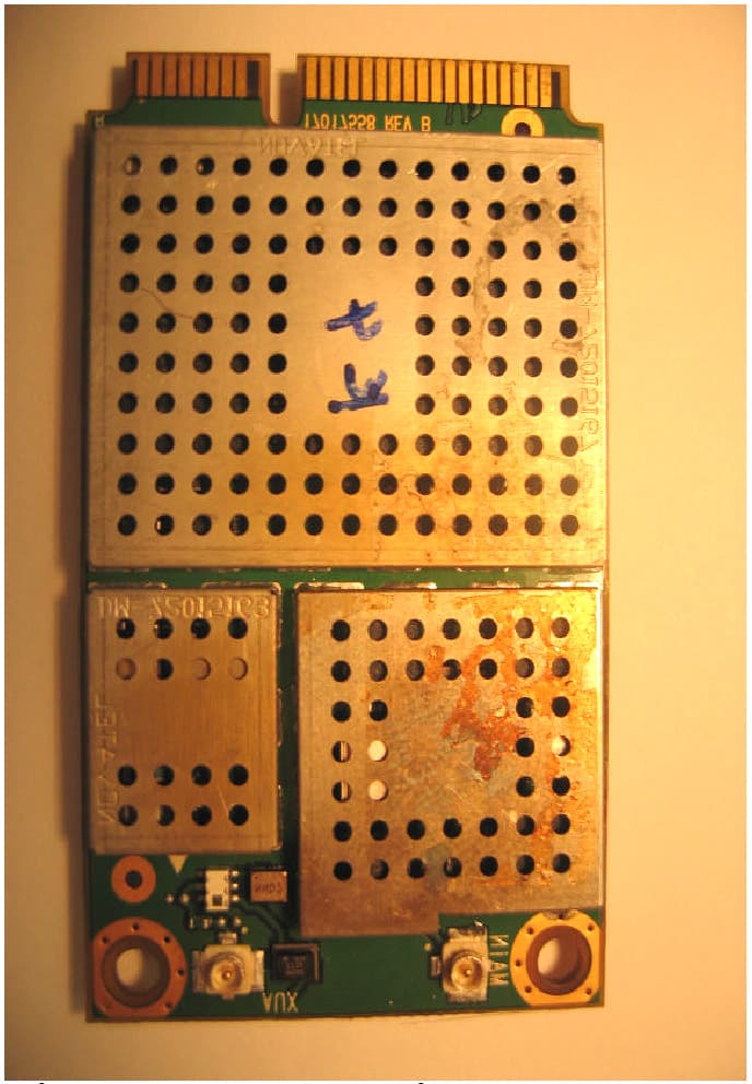
Click to zoom
Application Details
- Equipment Class
- PCB - PCS Licensed Transmitter
- Date of Grant
- Apr 11, 2007
- Application Purpose
- Original Equipment
- Date of Application
- Jan 29, 2007
- Equipment Note
- Model 02
- Frequency Range
- 824.70000000 - 848.33000000
- Company
- OQO, Inc.
- Country
- United States
Documents & Files
Document Text
Text extracted from the exhibit documents filed with the FCC. Open a document above to read the original.
Users Manual
OQO OQO OQO OQO model 02 model 02 model 02 model 02 Start Guide Copyright © 2006 OQO, Inc. All rights reserved. OQO, Inc. 583 Shotwell Street San Francisco, CA 94110 (415) 430 – 6200 http://www.oqo.com The information in this guide is subject to change without notice. OQO makes no warranty of any kind with regard to this manual, including, but not limited to, the implied warranties of merchantability and fitness for a particular purpose. OQO shall not be held liable for errors contained herein or direct, indirect, special, incidental, or consequential damages in connection with the furnishing, performance, or use of this material. Trademarks Bluetooth is a registered trademark of Bluetooth SIG, Inc. Kensington is a registered trademark of ACCO Brands. Microsoft and Windows are registered trademarks of Microsoft Corporation. OQO is a registered trademark of OQO, Inc. Stowaway is a registered trademark of Think Outside Inc. Targus is a registered trademark of Targus Group International. Timbuk2 is a registered trademark of Timbuk2 Designs, Inc. or its subsidiaries. TrackStik is a registered trademark of CTS Corporation. Tumi is a registered trademark of Tumi, Inc. Wi-Fi is a registered trademark of Wireless Ethernet Compatibility Alliance. Patents FCC Statement This equipment has been tested and found to comply with the limits for a Class B digital device, pursuant to Part 15 of the FCC Rules. These limits are designed to provide reasonable protection against harmful interference in a residential installation. This equipment generates, uses, and can radiate radio frequency energy and, if not installed and used in accordance with the instructions, may cause harmful interference to radio communications. However, there is no guarantee that interference will not occur in a particular installation. If this equipment does cause harmful interference to radio or television reception, which can be determined by turning the equipment off and on, the user is encouraged to try to correct the interference by one or more of the following measures: (1) Reorient or relocate the receiving antenna. (2) Increase the separation between the equipment and the receiver (3) Connect the equipment into an outlet on a circuit different from that to which the receiver is connected. (4) Consult the dealer or an experienced radio/TV technician for help. The highest SAR value for the personal computer system when next to the body, as described in this user guide, is 1.170 W/kg. No separation from the body is required when the wireless personal computer system is in operation, as the SAR measurements were taken with the unit "touching" the surface of the body. This device was tested for SAR compliance in the lap held configuration. If the device is purchased with the WWAN option, a whip antenna is utilized for WWAN coverage. When operating in WWAN mode, the whip antenna should be pulled out and up to the vertical position. In order to comply with FCC RF exposure requirements, and to align with the SAR test configuration, users must use the antenna in the vertical position during WW AN operation. This Class [B] digital apparatus complies with Canadian ICES-003. Cet appareil numérique de la classe [B] est conforme à la norme NMB-003 du Canada. The IEEE 802.11a device for the band 5150-5250 MHz is only for indoor usage, to reduce the potential for harmful interference to co-channel mobile satellite systems. Caution: Any changes or modifications not expressly approved by OQO for compliance will void the user's authority to operate the equipment. Declaration of Conformity We, OQO, Inc. 583 Shotwell Street, San Francisco, California, USA, 415.430.6200, declare under our sole responsibility that the product, OQO model 02 , complies with Part 15 of FCC Rules. Operation is subject to the following two conditions: (1) This device may not cause harmful interference, and (2) This device must accept any interference received, including interference that may cause undesired operation.
Users Manual
table of contents 1. what’s in the box 2. introducing the model 02 3. powering up and down 4. removing and attaching the battery 5. using the thumb keyboard and track stick 6. using the TouchScrollers, digital pen, and other screen features 7. connecting to a network 8. connecting the docking station and peripherals 9. installing software and copying files 10. using the model 02 security features 11. model 02 accessories 12. product support 3 4 6 8 10 12 14 16 18 20 22 24 what’s in the box Begin by comparing the list below to what’s in the box. You should find: OQO model 02 computer with standard battery pre-installed screen protector universal power supply and AC power cord VGA/Ethernet adapter spare track stick cap Microsoft ® Start Here guide OQO start guide with Windows ® XP reinstallation CD If you ordered Windows XP Tablet PC Edition 2005 with your model 02, you will also find a digital pen and carrying case in the box. If you ordered your model 02 with integrated Wireless Wide Area Network (WWAN) technology, your box will also include an instruction card for service activation. • • • • • • • Any accessories you ordered will be packed separately. If anything is missing, contact us by phone at 1-877-676-6688 or email [email protected]. Please register your OQO model 02 by visiting http://www.oqo.com/support. 3 introduction Welcome to the OQO model 02 computer. The model 02 is a full-featured Windows XP computer that gives you the total productivity you need to fulfill your personal and professional requirements. mobility The model 02 is the world’s smallest Windows Vista™ Capable computer. Its mobile form factor allows you to take it anywhere and its ergonomic design facilitates usability on the go. Because the model 02 uses the Windows XP operating system, you have uncompromised access to software applications and seamless connectivity – anytime, anywhere – via WiFi, Ethernet, Bluetooth ® , or Wireless Wide Area Network (WWAN) technology. flexibility While you’re on the go, the model 02 is your standalone, handheld computer with its own integrated keyboard, track stick, and capacitive TouchScrollers. The rugged, magnesium alloy chassis with shock mounted hard drive and active drop detect technology helps protect your data in the event your model 02 is dropped. At the office, the model 02 functions as your desktop computer connected to an external monitor, keyboard, and mouse. Also available is an array of accessories and a docking station that provides additional usage modes. power The model 02 was designed to deliver the total computing performance necessary to achieve personal and professional productivity, anytime and anywhere. The model 02 – with its robust processing power, Windows XP operating system, application compatibility, memory and storage capacity, and unparalleled connectivity options – is everything you need to meet your total productivity requirements. 4 5 powering up and down Your model 02 ships with a screen protector and battery attached. To turn on your model 02, press the power button located on the left side of the computer. When idle, conserve battery power by putting your computer in Standby or Hibernate mode. To charge the battery, connect the power supply to the model 02 as shown at right, and then plug into an outlet. The battery will charge whenever the computer is connected to an outlet. standby mode Standby mode reduces the power consumption of your computer by cutting power to non-critical hardware components. The system maintains power to your computer’s random access memory (RAM), which allows the system to quickly restore your active applications and files. To put your computer into Standby mode, press the power button. hibernate mode Hibernate mode saves your current system state to the hard disk drive and then powers down your computer. When you power up again, your open files and applications are re - stored just as you left them. Hibernate mode draws no power and is best for conserving battery life and changing batteries. To put your computer into Hibernate mode, select ‘Shut Down’ from the Start menu and choose the ‘Hibernate’ option or press the ‘H’ key on your keyboard. conserving battery power Additional ways to conserve battery power include: Turn off wireless radios when not in use. Turn off the keyboard backlight. Lower the internal display brightness. Adjust power settings in the Power Options control panel. • • • • 6 docking connector power button power supply 7 power removing and attaching the battery On the model 02, a fully charged battery typically provides 2 to 3 hours of operating time depending on usage. Double capacity batteries that provide up to 6 hours of charge are also available at http://www.oqo.com/store. charging the battery A battery fuel gauge is located on the right side of the battery. When pressed and released, the fuel gauge will illuminate to indicate remaining battery power. While the battery is charging, the fuel gauge lights flash in sequence. A standalone battery detached from the model 02 can be charged using a battery charging adapter (optional accessory) with your power supply. removing the battery Before replacing the battery, the computer should be plugged into an outlet, shut down, or placed in Hibernate mode. Removal of the battery while in Standby mode may result in loss of user and system data. To remove the battery, press the battery release button located next to the power button and lift the battery away from the computer. attaching the battery To attach the battery, rest the battery hooks in the slots alongside the back edge of the computer before lowering the battery onto the computer. Press the battery against the computer until the latch clicks. 8 battery battery release battery fuel gauge insert both battery hooks to attach battery 9 using the thumb keyboard and track stick When using your model 02 as a handheld computer, use the thumb keyboard and track stick for input and navigation. using t…
Text truncated - open the document above for the full version.
External Photos
OQO Model 02 – Figures SHD-A 7 YWFS Top Bottom Left Front, Display Closed Front, Display Open, Keyboard Exposed 802.11a/b/g Embedded Module Bluetooth Embedded Module Front View, Display Closed, Keyboard Exposed Front View, Display Closed, Covering Keyboard Inside Rear Cover Internal Photo Indicating WWAN and WLAN Transceivers WWAN module (PKRNVWEV620) 802.11a/b/g Embedded Module OQO Model 02 - Embedded Antennas Left-hand side 11 mm 31 mm Area inside cover for embedded antennas. Embedded antennas – seen without external black antenna covers. OQO Model 02 - Embedded Antennas Right-hand side 11 mm 31 mm Area inside cover for embedded antennas. Embedded antennas – seen without external black antenna covers. OQO Model 02 –Whip and Embedded Antennas 110 mm Whip antenna – WWAN. 88 mm 147 mm Embedded antennas on side of unit. Embedded antennas on side of unit.
ID Label/Location Info
FCC ID: SHD-A7YWFS IC: 6026A-A7YWFS
ID Label/Location Info
David Waitt From: Juan Martinez [[email protected]] Sent: Thursday, November 02, 2006 11:31 AM To: [email protected] Cc: David Bare; Mark Briggs; [email protected]; [email protected] Subject: Fwd: Response to Inquiry to FCC (Tracking Number 509537) Importance: High 11/11/2006 David, Here is the reply from the FCC regarding OQO's FCC ID Label being under the battery as being acceptable as long as the label is visible at time of purchase. Thanks, Juan M. Delivered-To: [email protected] Date: Thu, 2 Nov 2006 10:41:00 -0500 (EST) From: Generic Office of Engineering Technology <[email protected]> Subject: Response to Inquiry to FCC (Tracking Number 509537) To: [email protected] Inquiry: A letter signed by a manufacture would like to receive an interpreation regarding Section 2.925. This is in regards to labeling of an handheld computer with unlicense radio products. The product itself is 3.5H x 5.5W. Please let us know of your decision as the manufacture needs a reply as soon as possible. --- Reply from Customer on 11/02/2006 --- Yes the manufacture will sell the device without the battery installed. Being this the case I am assuming FCC will be ok with the unit having the label under the battery as long as the battery its not installed at time of purchase. Is my assumtion correct? Thanks. Response: At this time, these are granted on a case by case basis. For this device, the label proposal is acceptable. Do not reply to this message. Please select the Reply to an Inquiry Response link f! rom the OET In quiry System to add any additional information pertaining to this inquiry. Sr. EMC Engineer Elliott Laboratories 11/11/2006
Internal Photos
OQO Model 02 – Figures SHD-A 7 YWFS Top Bottom Left Front, Display Closed Front, Display Open, Keyboard Exposed 802.11a/b/g Embedded Module Bluetooth Embedded Module Front View, Display Closed, Keyboard Exposed Front View, Display Closed, Covering Keyboard Inside Rear Cover Internal Photo Indicating WWAN and WLAN Transceivers WWAN module (PKRNVWEV620) 802.11a/b/g Embedded Module OQO Model 02 - Embedded Antennas Left-hand side 11 mm 31 mm Area inside cover for embedded antennas. Embedded antennas – seen without external black antenna covers. OQO Model 02 - Embedded Antennas Right-hand side 11 mm 31 mm Area inside cover for embedded antennas. Embedded antennas – seen without external black antenna covers. OQO Model 02 –Whip and Embedded Antennas 110 mm Whip antenna – WWAN. 88 mm 147 mm Embedded antennas on side of unit. Embedded antennas on side of unit.
Internal Photos
Top Side With Shields – Mini Express Card Bottom Side With Shield Mini Express Card Top Side Without Shields Mini Express Card Bottom Side Without Shields Mini Express Card
RF Exposure Info
Dosimetric Assessment Test Report for the OQO Mini Computer FCC ID: SHD-A7YWFS Tested and Evaluated In Accordance With FCC OET 65 Supplement C: 01-01 Prepared for OQO 583 Shotwell Street San Francisco, CA 94110-2011 Engineering Statement: The measurements shown in this report were made in accordance with the procedures specified in Supplement C to OET Bulletin 65 of the Federal Communications Commission (FCC) Guidelines [FCC 2001], IEEE Std. 1528- 2003 and Industry Canada RSS-102 for uncontrolled exposure. I assume full responsibility for the accuracy and completeness of these measurements, and for the qualifications of all persons taking them. It is further stated that upon the basis of the measurements made, the equipment evaluated is capable of compliance for localized specific absorption rate (SAR) for uncontrolled environment/general population exposure limits specified in ANSI/IEEE Std. C95.1-2005. SAR Evaluation Certificate of Compliance FCC ID: SHD-A7YWFS APPLICANT: OQO Applicant Name and Address: OQO 583 Shotwell Street San Francisco, CA 94110-2011 Test Location: MET Laboratories, Inc. 4855 Patrick Henry Dr. Bldg #6 Santa Clara, CA 95054 USA EUT: Model 02 Mini Computer Date of Receipt: December 26, 2006 Device Category: FCC Parts 22, 24, 15.247, and 15.407 RF exposure environment: Uncontrolled Exposure/General Population RF exposure category: Portable Power supply: 3.7VDC 4500 and 9000mAh batteries and AC Antennas: Internal and Whip Production/prototype: Production Modulation: CDMA, DSSS and OFDM Duty Cycle: 100% TX Range: 824-848MHz 1851-1910MHz 2412-2462MHz 5150-5250MHz 5745-5805MHz Maximum RF Power Output 24.5dBm 24.5dBm 20.1dBm 17.0dBm 13.8dBm Shawn McMillen Senior Engineer INTRODUCTION ................................................................................................................................................ 4 SAR DEFINITION ............................................................................................................................................... 4 DESCRIPTION OF DEVICE UNDER TEST (EUT) ..........................................................................................5 SAR MEASUREMENT SYSTEM....................................................................................................................... 6 MEASUREMENT SUMMARY........................................................................................................................... 7 DATA EVALUATION PROCEDURES ............................................................................................................. 16 SYSTEM PERFORMANCE CHECK................................................................................................................ 18 SIMULATED EQUIVALENT TISSUES ........................................................................................................... 19 SAR SAFETY LIMITS ...................................................................................................................................... 20 ROBOT SYSTEM SPECIFICATIONS .............................................................................................................. 21 1.1. Specifications ................................................................................................................ 21 1.2. Data Acquisition Electronic (Dae) System: .................................................................. 21 1.3. Phantom(s): ................................................................................................................... 21 PROBE SPECIFICATIONS EX3DV3 ............................................................................................................... 22 SAR Measurement System ................................................................................................................................. 23 1.4. RX90BL Robot ............................................................................................................. 23 1.5. Robot Controller ........................................................................................................... 23 1.6. Light Beam Switch ....................................................................................................... 23 1.7. Data Acquisition Electronics ........................................................................................ 23 1.8. Electo-Optical Converter (EOC)................................................................................... 24 1.9. Measurement Server ..................................................................................................... 24 1.10. Dosimetric Probe ...................................................................................................... 24 1.11. SAM Phantom........................................................................................................... 24 1.12. Planar Phantom ......................................................................................................... 24 1.13. Validation Planar Phantom ....................................................................................... 24 1.14. Device Holder ........................................................................................................... 25 1.15. System Validation Kits ............................................................................................. 25 TEST EQUIPMENT LIST.................................................................................................................................. 26 MEASUREMENT UNCERTANTIES................................................................................................................ 27 REFERENCES ................................................................................................................................................... 29 EUT PHOTOS .....................................................................................................................................…
Text truncated - open the document above for the full version.
RF Exposure Info
APPENDIX B - SYSTEM PERFORMANCE CHECK 835MHz body Validation Date/Time: 1/03/2007 7:16:51 AM DUT: Dipole 835 MHz; Type: D835V2; Serial: D835V2 Medium Notes: Ambient Temp: 23.0 deg C; Fluid Temp: 21.0 deg C Communication System: CW; ; Frequency: 835 MHz;Duty Cycle: 1:1 Medium: M835 Medium parameters used: f = 835 MHz; σ = 0.97 mho/m; ε r = 55.2; ρ = 1000 kg/m 3 Phantom section: Flat Section - Probe: EX3DV3 - SN3511; ConvF(9.55, 9.55, 9.55); Calibrated: 1/23/2006 - Sensor-Surface: 4mm (Mechanical Surface Detection) - Electronics: DAE3 Sn584; Calibrated: 9/22/2005 - Phantom: SAM with CRP; Type: SAM; Serial: TP 1310 - Measurement SW: DASY4, V4.7 Build 53; Postprocessing SW: SEMCAD, V1.8 Build 172 Validation/Area Scan (61x81x1): Measurement grid: dx=15mm, dy=15mm Maximum value of SAR (interpolated) = 2.83 mW/g Validation/Zoom Scan (7x7x7) (7x7x7)/Cube 0: Measurement grid: dx=5mm, dy=5mm, dz=5mm Reference Value = 54.4 V/m; Power Drift = -0.003 dB Peak SAR (extrapolated) = 3.95 W/kg SAR(1 g) = 2.66 mW/g; SAR(10 g) = 1.76 mW/g Maximum value of SAR (measured) = 2.87 mW/g 1900MHz body validation Date/Time: 01/02/2007 7:07:04 AM DUT: 1900 MHz validation dipole; Type: Dipole; Serial: 001 Communication System: CW; ; Frequency: 1900 MHz;Duty Cycle: 1:1 Medium: M1900 Medium parameters used: f = 1900 MHz; σ = 1.57 mho/m; ε r = 55.6; ρ = 1000 kg/m 3 Phantom section: Flat Section - Probe: EX3DV3 - SN3511; ConvF(8.14, 8.14, 8.14); Calibrated: 1/23/2006 - Sensor-Surface: 4mm (Mechanical Surface Detection) - Electronics: DAE3 Sn584; Calibrated: 9/22/2005 - Phantom: SAM with CRP; Type: SAM; Serial: TP 1310 - Measurement SW: DASY4, V4.7 Build 44; Postprocessing SW: SEMCAD, V1.8 Build 171 Area Scan (61x101x1): Measurement grid: dx=10mm, dy=10mm Maximum value of SAR (interpolated) = 12.3 mW/g Zoom Scan (7x7x7)/Cube 0: Measurement grid: dx=5mm, dy=5mm, dz=5mm Reference Value = 87.6 V/m; Power Drift = -0.02 dB Peak SAR (extrapolated) = 19.9 W/kg SAR(1 g) = 10.9 mW/g; SAR(10 g) = 5.62 mW/g Maximum value of SAR (measured) = 12.3 mW/g Validation 2450MHz Body Date/Time: 12/28/2006 12:36:57 PM DUT: Dipole 2450 MHz; Type: D2450V2; Serial: 1S2452 Communication System: CW; ; Frequency: 2450 MHz;Duty Cycle: 1:1 Medium: M2450 Medium parameters used: f = 2450 MHz; σ = 2.04 mho/m; ε r = 54.5; ρ = 1000 kg/m 3 Phantom section: Flat Section Probe: EX3DV3 - SN3511; ConvF(7.8, 7.8, 7.8); Calibrated: 1/23/2006 Sensor-Surface: 4mm (Mechanical Surface Detection) Electronics: DAE3 Sn584; Calibrated: 9/22/2005 Phantom: SAM with CRP; Type: SAM; Serial: TP 1310 Measurement SW: DASY4, V4.7 Build 44; Postprocessing SW: SEMCAD, V1.8 Build 171 Area Scan (61x81x1): Measurement grid: dx=10mm, dy=10mm Maximum value of SAR (interpolated) = 16.2 mW/g Zoom Scan (7x7x7)/Cube 0: Measurement grid: dx=5mm, dy=5mm, dz=5mm Reference Value = 88.7 V/m; Power Drift = -0.010 dB Peak SAR (extrapolated) = 28.6 W/kg SAR(1 g) = 13.9 mW/g; SAR(10 g) = 6.36 mW/g Maximum value of SAR (measured) = 15.8 mW/g 5200MHz Validation Date/Time: 12/28/2006 7:57:49 AM DUT: Dipole 5500 MHz; Type: D5500V2; Serial: D5500V2 - SN:001 Communication System: CW; ; Frequency: 5200 MHz;Duty Cycle: 1:1 Medium: 5500 MHz Body Medium parameters used: f = 5200 MHz; σ = 5.37 mho/m; ε r = 48.2; ρ = 1000 kg/m 3 Phantom section: Flat Section - Probe: EX3DV3 - SN3511; ConvF(4.68, 4.68, 4.68); Calibrated: 1/23/2006 - Sensor-Surface: 4mm (Mechanical Surface Detection)Sensor-Surface: 2mm (Mechanical Surface Detection) - Electronics: DAE3 Sn584; Calibrated: 9/22/2005 - Phantom: SAM with CRP; Type: SAM; Serial: TP 1310 - Measurement SW: DASY4, V4.7 Build 44; Postprocessing SW: SEMCAD, V1.8 Build 172 Area Scan (81x81x1): Measurement grid: dx=10mm, dy=10mm Maximum value of SAR (interpolated) = 16.8 mW/g Zoom Scan (9x9x9)/Cube 0: Measurement grid: dx=4.3mm, dy=4.3mm, dz=3mm Reference Value = 54.9 V/m; Power Drift = 0.07 dB Peak SAR (extrapolated) = 77.0 W/kg SAR(1 g) = 17 mW/g; SAR(10 g) = 5.13 mW/g Maximum value of SAR (measured) = 32.1 mW/g 5800MHz Validation Date/Time: 12/27/2006 7:23:39 AM DUT: Dipole 5500 MHz; Type: D5500V2; Serial: D5500V2 - SN:001 Communication System: CW; ; Frequency: 5800 MHz;Duty Cycle: 1:1 Medium: 5500 MHz Body Medium parameters used: f = 5800 MHz; σ = 6.39 mho/m; ε r = 48.4; ρ = 1000 kg/m 3 Phantom section: Flat Section - Probe: EX3DV3 - SN3511; ConvF(4.1, 4.1, 4.1); Calibrated: 1/23/2006 - Sensor-Surface: 4mm (Mechanical Surface Detection)Sensor-Surface: 2mm (Mechanical Surface Detection) - Electronics: DAE3 Sn584; Calibrated: 9/22/2005 - Phantom: SAM with CRP; Type: SAM; Serial: TP 1310 - Measurement SW: DASY4, V4.7 Build 53; Postprocessing SW: SEMCAD, V1.8 Build 172 Area Scan (81x81x1): Measurement grid: dx=10mm, dy=10mm Maximum value of SAR (interpolated) = 17.5 mW/g Zoom Scan (9x9x9)/Cube 0: Measurement grid: dx=4.3mm, dy=4.3mm, dz=3mm Reference Value = 53.4 V/m; Power Drift = 0.14 dB Peak SAR (extrapolated) = 73.0 W/kg SAR(1 g) = 16.8 mW/g; SAR(10 g) = 5.18 mW/g Maximum value of SAR (measured) = 32.8 mW/g APPENDIX C – PROBE CALIBRATION CERTIFICATE APPENDIX D – DIPOLE CALIBRATION CERTIFICATE CALIBRATION CERTIFICATE Object: 835MHz Validation Dipole; serial # 493 Calibration Procedure: Calibration procedure for a validation dipole Calibration Date: October 4, 2005 Condition of the Calibrated Item: In Tolerance This calibration certificate documents the traceability to national standards, which realize the physical units of measurements (SI). The measurements and the uncertainties with confidence probability are given on the following pages and are part of the certificate. All calibrations have been conducted in a closed laboratory facility: environment temperature (21 ± 3) o C and humidity < 70% Calibration equipment used Model Type Serial Number MET Asset # Cal Date Anritsu Power Meter ML2488A 6K00001832 1S2430 June 2005 Anritsu Power Sensor 030864 1S2432 Jan 2005 HP E4418B Power Meter GB40205140 1S2276 June 2005 HP 8482A Power Sensor 2607A11286 1S2140 June 2005 83650B …
Text truncated - open the document above for the full version.
RF Exposure Info
From: MET Laboratories, Inc. 33439 Western Ave. Union City, CA 94587 Re: OQO application for FCC ID SHD-A7YWFS The EUT was initially evaluated for RF exposure with the WLAN swivel antenna in various positions relative to the phantom surface. Please see photos and SAR plots below. With the antenna in an “extreme position”, parallel to the surface of the phantom as shown in Fig. 2, the RF exposure was 0.567 mW/g @ 835MHz and 1.38 mW/g @ 1880MHz. This position, however, was inconsistent with the intended end use as well as the user’s manual instructions for intended antenna positions. As a result, the antenna was tested in a position consistent with the user manual, as shown in Figure 1, which gave SAR results of 0.094 mW/g @ 835MHz and 0.249 mW/g @ 1880MHz. Based on the findings above it was concluded that this particular swivel antenna design is indeed sensitive to angles relative to the phantom surface but that small deviations, ± 30 0 from the intended user position, would give relatively small deviations from the observed RF exposure, excluding any measurement uncertainty. Fig. 1: Intended operation position of WLAN swivel antenna with whip oriented vertically. Fig. 2: Extreme position of swivel antenna Extreme Position, Parallel to Phantom Surface Mid CH 835MHz/Back side/std batt/ant parallel Date/Time: 12/21/2006 8:13:36 AM DUT: OQO Bottom Side; Type: WLAN Bottom; Serial: EVT3F065 Medium Notes: Ambient Temp: 23.1 deg C; Fluid Temp: 22.1 deg C Communication System: CDMA; ; Frequency: 835 MHz;Duty Cycle: 1:1 Medium: M900 Medium parameters used: f = 835 MHz; σ = 0.96 mho/m; ε r = 55.9; ρ = 1000 kg/m 3 Phantom section: Flat Section - Probe: ET3DV6 - SN1793; ConvF(6.3, 6.3, 6.3); Calibrated: 9/20/2005 - Sensor-Surface: 4mm (Mechanical And Optical Surface Detection) - Electronics: DAE3 Sn584; Calibrated: 9/22/2005 - Phantom: SAM with CRP; Type: SAM; Serial: TP 1310 - Measurement SW: DASY4, V4.7 Build 53; Postprocessing SW: SEMCAD, V1.8 Build 172 Area Scan (61x141x1): Measurement grid: dx=10mm, dy=10mm Maximum value of SAR (interpolated) = 0.610 mW/g Zoom Scan (7x7x7)/Cube 0: Measurement grid: dx=5mm, dy=5mm, dz=5mm Reference Value = 23.3 V/m; Power Drift = 0.085 dB Peak SAR (extrapolated) = 1.18 W/kg SAR(1 g) = 0.567 mW/g; SAR(10 g) = 0.343 mW/g Maximum value of SAR (measured) = 0.619 mW/g Extreme Position, Parallel to Phantom Surface Mid Ch 1880MHz/back side/std batt/ant parallel Date/Time: 12/21/2006 9:34:52 AM DUT: OQO Bottom Side; Type: WLAN Bottom; Serial: EVT3F065 Medium Notes: Ambient Temp: 24.0 deg C, Fluid Temp: 22.3 deg C Communication System: CDMA; ; Frequency: 1800 MHz;Duty Cycle: 1:1 Medium: M1800 Medium parameters used: f = 1800 MHz; σ = 1.58 mho/m; ε r = 55.7; ρ = 1000 kg/m 3 Phantom section: Flat Section - Probe: ET3DV6 - SN1793; ConvF(4.8, 4.8, 4.8); Calibrated: 9/20/2005 - Sensor-Surface: 4mm (Mechanical And Optical Surface Detection) - Electronics: DAE3 Sn584; Calibrated: 9/22/2005 - Phantom: SAM with CRP; Type: SAM; Serial: TP 1310 - Measurement SW: DASY4, V4.7 Build 53; Postprocessing SW: SEMCAD, V1.8 Build 172 Area Scan (61x141x1): Measurement grid: dx=10mm, dy=10mm Maximum value of SAR (interpolated) = 1.53 mW/g Zoom Scan (7x7x7)/Cube 0: Measurement grid: dx=5mm, dy=5mm, dz=5mm Reference Value = 19.0 V/m; Power Drift = -0.009 dB Peak SAR (extrapolated) = 3.65 W/kg SAR(1 g) = 1.38 mW/g; SAR(10 g) = 0.646 mW/g Maximum value of SAR (measured) = 1.56 mW/g
Test Report
File: R65381 Rev 1 Page 1 of 23 2016-01 Electromagnetic Emissions Test Report and Application for Grant of Equipment Authorization pursuant to Industry Canada RSS-Gen Issue 1 / RSS 210 Issue 6 FCC Part 15 Subpart C on the OQO Transmitter Model: Model 02 IC: 6026A-A7YWFS FCC ID: SHD-A 7YWFS GRANTEE: OQO 583 Shotwell Street San Francisco, CA. 941 11 TEST SITE: Elliott Laboratories, Inc. 684 W. Maude Ave Sunnyvale, CA 94086 REPORT DATE: September 15, 2006 FINAL TEST DATE: August 9, August 11, August 15, August 25 and September 1, 2006 AUTHORIZED SIGNATORY: ______________________________ Juan Martinez Senior EMC Engineer Elliott Laboratories, Inc. is accredited by the A2LA, certificate number 2016-01, to perform the test(s) listed in this report. This report shall not be reproduced, except in its entirety, without the written approval of Elliott Laboratories, Inc. Elliott Laboratories, Inc. -- EMC Department Test Report Report Date: Se…
Text truncated - open the document above for the full version.
Contact Information
Applicant
Bob Hymes(Engineering Program Manager)
Technical Contact
Elliott Laboratories, Inc.Juan Martinez
[email protected]408-245-7800
684 West Maude Ave · Sunnyvale, California · United States
Non-Technical Contact
Elliott LaboratoriesDavid Michael Guidotti
[email protected]408-245-7800
Test Firm
Elliott Laboratories Inc.David Bare
Technical Specifications
| # | Rule Parts | Frequency Range | Power Output | Emission | Tolerance |
|---|---|---|---|---|---|
| 2 | 22H | 824.7 MHz - 848.33 MHz | 282.00 mW | 1M25F9W | 2.5 ppm |
Other Applications from OQO, Inc.
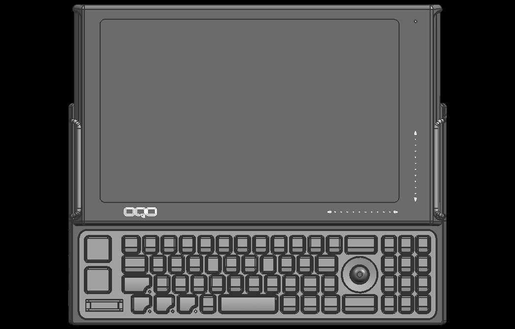
SHD-A8YWFS
Sep 29, 2007Handheld Computer
Equipment Class
DSS - Part 15 Spread Spectrum Transmitter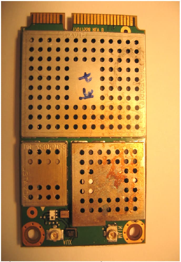
SHD-A6YWFS
Jan 16, 2007Model 02
Equipment Class
DTS - Digital Transmission System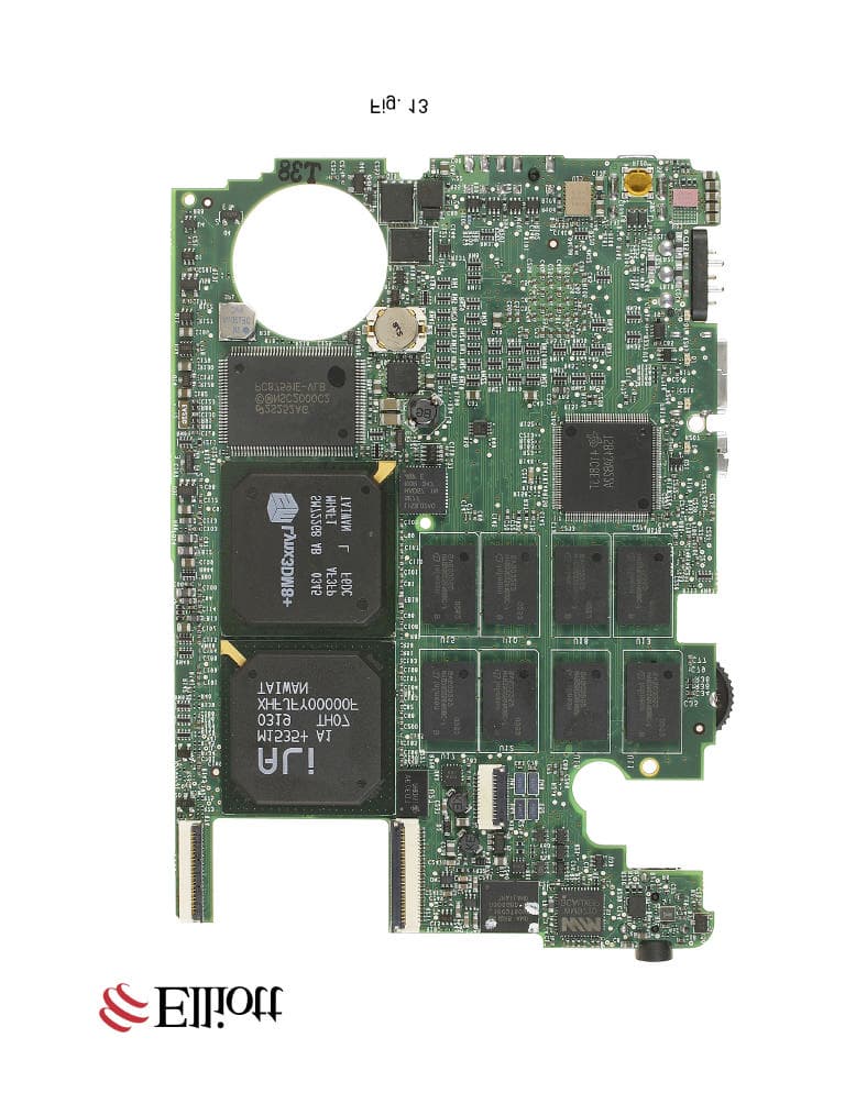
SHD-A4YWFS
Dec 16, 2004Handheld Computer
Equipment Class
DTS - Digital Transmission System