SHD-A8YWFSHandheld Computer
OQO, Inc.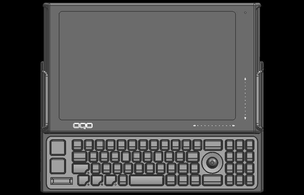
Click to zoom
Application Details
- Equipment Class
- DSS - Part 15 Spread Spectrum Transmitter
- Date of Grant
- Sep 29, 2007
- Application Purpose
- Original Equipment
- Date of Application
- Sep 26, 2007
- Equipment Note
- Handheld Computer
- Frequency Range
- 2402.00000000 - 2480.00000000
- Company
- OQO, Inc.
- Country
- United States
Documents & Files
Document Text
Text extracted from the exhibit documents filed with the FCC. Open a document above to read the original.
Users Manual
OQO OQO OQO OQO model 02 model 02 model 02 model 02 Start Guide Copyright © 2006 , 2007 OQO, Inc. All rights reserved. OQO, Inc. 583 Shotwell Street San Francisco, CA 94110 (415) 430 – 6200 http://www.oqo.com The information in this guide is subject to change without notice. OQO makes no warranty of any kind with regard to this manual, including, but not limited to, the implied warranties of merchantability and fitness for a particular purpose. OQO shall not be held liable for errors contained herein or direct, indirect, special, incidental, or consequential damages in connection with the furnishing, performance, or use of this material. Trademarks Bluetooth is a registered trademark of Bluetooth SIG, Inc. Kensington is a registered trademark of ACCO Brands. Microsoft and Windows are registered trademarks of Microsoft Corporation. OQO is a registered trademark of OQO, Inc. Stowaway is a registered trademark of Think Outside Inc. Targus is a registered trademark of Targus Group International. Timbuk2 is a registered trademark of Timbuk2 Designs, Inc. or its subsidiaries. TrackStik is a registered trademark of CTS Corporation. Tumi is a registered trademark of Tumi, Inc. Wi-Fi is a registered trademark of Wireless Ethernet Compatibility Alliance. Patents FCC Statement This equipment has been tested and found to be comply with the limits for a Class B digital device, pursuant to Part 15 of the FCC Rules. These limits are designed to provide reasonable protection against harmful interference in a residential installation. This equipment generates, uses, and can radiate radio frequency energy and, if not installed and used in accordance with the instructions, may cause harmful interference to radio communications. However, there is no guarantee that interference will not occur. If this equipment does cause harmful interference to radio or television reception, which can be determined by turning the equipment off and on, the user is encouraged to try to correct the interference by one or more of the following measures: 1) Reorient the receiving antenna. 2) Increase the separation between the equipment and receiver. 3) Connect the equipment into an outlet on a circuit different from that to which the receiver is connected. 4) Consult the dealer or an experienced technician for help. The highest SAR value for the computer when next to the body, as described in this user guide, is as follows: for the Regulatory Model Number (RMN) 2042: 0.679 W/kg; for the RMN 2050: 0.625 W/kg; for the RMN 2060: 0.625 W/kg. No separation from the body is required when the wireless computers is in operation, as the SAR measurements were taken with the unit “touching” the surface of the body. This device was tested for SAR compliance in the lap held configuration. If the device is purchased with the WWAN option, a whip antenna is utilized for WWAN coverage. When operating in WWAN mode, the whip antenna should be pulled out and up to the vertical position. In order to comply with FCC RF exposure requi4rements, and to align with the SAR test configuration, users must maintain a separation distance of 1.5 cm between the antenna and all persons, and maintain the antenna in the vertical position during WWAN operation. This Class [B] digital apparatus complies with Canadian ICES-003. Cet appareil numérique de la class [B] est conformé à la norme NMB-003 du Canada. The IEEE 802.11a device for the band 5150-5250 MHz is only for indoor usage, to reduce the potential for harmful interference to co-channel mobile satellite systems. In addition, users should also be cautioned to take note that high-power radars are allocated as primary users (meaning they have priority) of the bands 5250-5350 MHz and 5650-5850 MHz and these radars could cause interference and/or damage to LE-LAN devices. Caution: Any changes or modifications not expressly approved by OQO for compliance will void the user’s authority to operate the equipment. FCC Radio Frequency Exposure and SAR The available scientific evidence does not show that any health problems are associated with using low power wireless devices. There is no proof, however, that low power wireless devices are absolutely safe. The exposure standard for low power wireless devices em - ploys a unit of measurement known as the Specific Absorption Rate, or SAR. Tests for SAR are conducted using standard op - erating positions accepted by the FCC and by Industry Canada with the device transmitting at its highest certified power level in all tested frequency bands. Although the SAR is determined at the highest certified power level, the actual SAR level of the device while operating can be well below the maximum value. This is because the device is designed to operate at the mini - mum power level required to reach the network. Before a low power wireless device is available for sale to the public in the US and Canada it must be tested and certified to the FCC and the Industry Canada that it does not exceed the limit established by each government for safe exposure. The personal computer (OQO model 02) has been tested and found to comply with the Federal Communications Committee guidelines on radio frequency (RF) energy exposure. Industry Canada This Class [B] digital apparatus complies with Canadian ICES- 003. Cet appareil numérique de la classe [B] est conformé à la norme NMB-003 du Canada. The term IC before the radio certification number only signifies that Industry Canada techni- cal specifications were met. FCC Declaration of Conformity We, OQO, Inc. 583 Shotwell Street, San Francisco, California, USA, 1-415-430-6200, declare under our sole responsibility that the product, OQO model 02, complies with Part 15 of FCC Rules. Operation is subject to the following two conditions: (1) This device may not cause harmful interference, and (2) This device must accept any interference received, including interference that may cause undesired operation. CE Declaration of Conformity We, OQO, Inc. 583 S…
Text truncated - open the document above for the full version.
Cover Letter(s)
Page 1 of 7 American TCB September 21, 2007 RE: FCC ID: SHD-A9YWFS Attention: Timothy Johnson Please find our responses to your comments on this application below: 1) Due to various concerns recently seen about proper authority being given to others for FCC and/or IC matters, the agency letter and/or confidentiality letter should be signed by someone traceable to have the proper authority. For instance, the FCC site shows Bob Hymes as the correct contact of authority for FCC matters. Therefore the agency letters should be signed by this contact or alternatively a letter showing who he has “deputized” (i.e. Roy Harlin/Hans Hartmann) to sign on his behalf may be provided as well. Please correct. See provided letter. 2) Please note that the 731 states the operating frequency for the DTS is 2412 to 2467MHz. Please note that for this type device the FCC limits the range of operation to 12 channels between 2412 to 2462MHz. Please correct the 731 and any other documentation to reflect the appropriate frequency range for this type device. See revised ATCB 731 and IC forms. 3 Some cover letters have information removed by using boxes to cover which can be moved or adjusted. Please correct the letters by deleting the information as appropriate. See the revised letters. 4) If the setup and external photos are to be part of the STC please note that the device can still be seen in the SAR report. If the setup photos are to be part of the STC, please remove them from the SAR report and provide them as a separate exhibit. The revised STC does not request that setup photos to be held confidential. 5) Short Term confidentiality in the main letter is referencing additional documents not shown in the short term confidentiality letters. This information should be consistent. It may be advisable to simply reduce the phrasing in the main letter to remove all mention of certain exhibits and simply cite that short term confidentiality is requested separately. See the revised STC letter. Page 2 of 7 6) For unlicensed devices approved as an entire device, the FCC desires pictures of the top and bottom of all boards in the device. It appears that many photographs are missing. Please review. See additional photographs. 7) For IC the model number must match as listed. Currently the label provided cites 2000, while the model on the IC form cites 2042. Please review and correct documentation as necessary. See the revised label diagram. The IC form was correct. 8) The information suggests that the label is located underneath the battery. However the exhibit which shows location appears to be on the outside of the device. Please provide a better exhibit to clearly show label placement. See the revised label diagram. The label is located underneath the battery, as surmised. Included in the application was a request to have the label under the battery. This was approved by the FCC in the previous version of the OQO device. Correspondence to this affect was included in the original submittal documentation. 9) The FCC label letter provided mentions that this device is identical except for changes to the EVDO revision number. This device does not appear to contain EVDO. Please review. See revised letter. 10) Bluetooth Operational description (page 9) cites +6dBm while the measured output is about 1 mW (6 dB lower). FCC expects the device to be tested at maximum output power. Please explain/review/correct as necessary. The output of the Bluetooth radio is limited to the level measured during testing, approx 1 mW. While the chip is capable of higher power, the OQO device limits the BT operation to Class 3 operation, as noted in the OQO Theory of Operation. 802.11 b/g items 11) Should the last note on page 35 of the test report be note 3? Otherwise table isn’t clear. Corrected. Page 3 of 7 12) Although 10 Hz is allowed as a average detector for average measurements falling in restricted bands under 15.247, for average plots on pages 47, 48, 52, 53, 67, 69, 72-73 typically a peak detector (not sample) are used for spurious restricted bands measurements. This fact may affect results as reported. Please review/correct. The plots presented in the test data are there to identify the location of the highest emissions, near or outside the band. No final readings are taken from the plot. The final measurements are taken using a peak and average detector, as noted in the tabular data. 13) Average power techniques were applied to 802.11b/g – therefore pages 44-45, 64- 65, and 85-86 should use –30dBc. The 802.11b power measurements were taken peak, therefore -20dBc was correct. The power for 802.11g and the 802.11a (5725-5850MHz) was taken average. The test data and report have been revised appropriately. 14) Average power techniques were applied to 802.11b/g – therefore page 47, 52, and following data tables should use –30dBc (i.e. limit of 62.4 dBuV/m/ -65.5 dBuV/m). The 802.11b power measurements were taken peak, therefore -20dBc was correct. 15) FYI...In the future, kindly reference the appropriate power and PSD methods applied from FCC KDB 558074. Noted. 16) FYI...It appears that power techniques for 802.11 are average, while the PSD was done using peak. Note that FCC KDB 558074 specifies specific PSD measurements depending on the power methods applied. Please take care in the future to observe this. Since current PSD method is considered worse case, further action on this item is not requested at this time. Noted. 17) Page 12 clearly states that no modifications were made. However other pages in the report (i.e. page 32) shows specific modifications necessary. Please review/correct as necessary. The report has been modified to note the modification. Page 4 of 7 18) Sections where power levels were reduced to meet requirements should also be considered as modifications (i.e. manufacturer must set maximum level to ___). Elliott does not consider these to be modifications, since we are typically working with a prototype and unique soft…
Text truncated - open the document above for the full version.
Cover Letter(s)
Page 1 of 3 American TCB September 26, 2007 RE: FCC ID: SHD-A8YWFS Attention: Timothy Johnson Please find our responses to your comments on this application below: 1) The current FCC agent letter is signed by Roy Harlin and also still contains a box which can be moved or adjusted. Please adjust this letter for these 2 issues as appropriate per our previous comments. See updated FCC agent letter. 2) The Standard Confidentiality Letter still mentions in the next to last paragraph that test photos, external photos, internal photos, and users manual require short term confidentiality (which is being requested separately) – which was previously mentioned in comment 5 but was likely not clear which letter was referenced. Additionally, this letter is also signed by Roy Harlin and not Harns Hartmann as well. Kindly adjust this letter for two issues. See updated Standard Confidentiality letter. 3) FYI......Regarding short term confidentiality, you are responsible for the following: a) Note that any documents held under the short-term confidentiality will automatically become public after 45 days. A manufacturer may extend this period up to an additional 45 days. This requires an additional cover letter requesting this extension must be submitted to ATCB a minimum of 7 days prior to the expiration of the original 45 day temporary grant of confidentiality. b) If the manufacturer engages in public marketing activities or otherwise publicizes the device prior to the expiration of the short-term confidentiality period, the applicant must immediately notify ATCB so the exhibits can be made publicly available. Noted. Comments passed on to the applicant. 4) Your response to previous comment 13 & 14 cites power was measured as peak. However peak data clearly cites the following Note 1 which equates to an average technique: Page 2 of 3 Previous comments provided cited: Average power techniques were applied to 802.11b/g – therefore pages 44-45, 64-65, and 85-86 should use –30dBc. and Average power techniques were applied to 802.11b/g – therefore page 47, 52, and following data tables shoudl use –30dBc (i.e. limit of 62.4 dBuV/m/ -65.5 dBuV/m). The Note 1 in the table for the 802.11b was incorrect. The plots show that power integration was performed over a max held, peak detector trace. The note in the table has been corrected. The -20dBc references are correct. The 802.11g power measurements were done using an average technique. Therefore, I have verified that all references for 802.11g measurements are for - 30dBc. 5) It appears that 15.207 is still used and mislabeled as restricted band references in the front of the report (see pages 7-11). Corrected. 6) Regarding the concern about the DFS question, please see Andy L. presentation, page 28 from February 2007. Original comment cited for clarity: 35) For DFS applications, the FCC has asked that the application include how DFS software security is – February 2007 TCBC training. See the revised Theory of operations. Note, the user has no ability to turn off any of the DFS functions since they are hardcoded into the Atheros chip. Page 3 of 3 Regards, Mark E Hill Staff Engineer
Cover Letter(s)
Page 1 of 1 American TCB September 27, 2007 RE: FCC ID: SHD-A8YWFS Attention: Timothy Johnson Please find our responses to your comments on this application below: 1) FYI.....802.11g limits in non-restricted band still appear at -20 dBc. However they are compliant to -30 dBc requirements and further corrections are not being requested. Noted. 2) Since operation of the 5475 – 5725 MHz band has been removed, please update the SAR report to remove this information as well. See Revised SAR Report. 3) Power measurements shown in the SAR report for 5150 – 5250 MHz exceed FCC output power limits. Please review. See Revised SAR Report. Cable loss was incorrectly calculated. 4) It still appears that the scanning volumes required by > 3 GHz SAR policies are not met. Please review. See Revised SAR Report. Clarification on the scan volume used included. Regards, Mark E Hill Staff Engineer
Cover Letter(s)
Federal Communications Commission, Authorization & Evaluation Division, 7435 Oakland Mills Road, Columbia, MD 21046 Gentlemen: This is your letter of authorization to accept our appointment of Elliott Laboratories, Inc. as Agent for OQO, 583 Shotwell St., San Francisco, CA, 94111, to sign applications before the Commission and to make representations to you on our behalf. Elliott Laboratories is to receive and exchange data between our company and the Commission. This authorization is made pursuant to Section 2.911(c) of the FCC Rules and expires on August 31, 2008. I hereby certify on behalf of OQO ("Applicant") that neither Applicant nor any party to the application (officers, directors, and 5% shareholders) is subject to a denial of Federal benefits that includes FCC benefits pursuant to section 5301 of the Anti-Drug Abuse Act of 1988. 21 U.S.C. 853a. Sincerely, Hans Hartmann Vice President of Engineering, OQO
Cover Letter(s)
Federal Communications Commission Authorization and Evaluation Div. Equipment Authorization Branch 7435 Oakland Mills Road Columbia, MD 21046 In re: OQO, Inc. Request for Short-Term Confidentiality To Whom It May Concern: In accordance with 0.457 and 0.459 of CFR 47, OQO requests short-term confidentiality for the internal photos and user’s manual of the attached test report. These documents contain detailed system and equipment descriptions and related information about the product, which OQO considers to be proprietary, confidential, and a custom design and otherwise, would not release to the general public. Since this design is a basis from which future technological products will evolve, OQO feels that this information would be of benefit to its competitors, and that the disclosure of the information in these documents would give our competitors an unfair advantage in the market. OQO understands that regardless of any future requests, Short Term Confidentiality for the items mentioned in the short term confidentiality request for this FCC ID, once granted, will end no later than 180 days from the grant date. Sincerely, Hans Hartmann Vice President of Engineering, OQO
Cover Letter(s)
Federal Communications Commission, Authorization & Evaluation Division, 7435 Oakland Mills Road, Columbia, MD 21046 Dear Examiner: I am writing to avoid the possibility of an inadvertent disclosure of proprietary information. The accompanying Form 731 is being filed with the commission on our behalf by Elliott Laboratories, Inc., a consulting and testing laboratory. Included as exhibits with the enclosed application are block diagrams, schematics, and a detailed description of the theory of operation of the device. It is our intention to provide the commission with a full disclosure of our product so that its merits can be evaluated. Indeed, we are pleased to provide any further information that the commission might wish to see. It is not our intention, however, to make our proprietary process a matter of public record. In view of the fact that the these documents disclose the mechanism of our process, we ask that these portions (block diagrams, schematics, and theory of operation) of our application be withheld from public inspection as provided under FCC section 0.459. These documents contain details of the proprietary operation of product. These details are not readily discernible - even to technically sophisticated individuals - from our hardware and constitute trade secrets. We request therefore that these documents be segregated from the body of our evaluation report and withheld from public inspection. Short-term confidentiality is being requested separately. Thank you for your attention. Please let the undersigned know if the Commission disagrees with our position or requires further justification. Sincerely, Hans Hartmann Vice President of Engineering, OQO
External Photos
Top Bottom Left Front, Display Closed Front, Display Open, Keyboard Exposed
External Photos
Front View, Display Closed, Keyboard Exposed Front View, Display Closed, Covering Keyboard
ID Label/Location Info
Federal Communications Commission, Authorization & Evaluation Division, 7435 Oakland Mills Road, Columbia, MD 21046 Gentlemen, OQO, Inc. is requesting an interpretation regarding Section 2.925 (d), which states that the FCC ID label shall be readily visible to the purchaser at the time of purchase. The design of the OQO product is such that the unit’s FCC ID will be readily visible to the user before installing the battery. Also, per Section 2.925 (d)(2), it further states that it will be "preferred that the label be visible at all times", but that it is not a prerequisite for approval. Although cellular handsets (licensed radios) are allowed to have the FCC ID underneath the battery, Section 2.925 does not reference such authorization being unique to cellular handsets. We request that the FCC allow section 2.925(d)(2) to be applicable to our device, since the product is too small to have the label anywhere else. Such a decision to allow certain radios, but not all, to have the FCC ID label underneath the battery is placing undue burden on the manufacture. OQO’s most recently certified product, the “Model 02”, with FCC ID SHD-A7YWFS, had its grant application in January of 2007. The FCC ID label was placed inside the battery compartment on that device. Authorization for this label location was given by the Commission in November 2006. That device is still manufactured and sold, and still adheres to the above FCC sections. The battery is not connected to the device when shipped to the customer. An explicit packaging label directs the customer to the FCC label on the inside of the battery compartment. OQO’s updated product, the subject of this request, is virtually identical to the original “Model 02” (increasing the CPU clock frequency from 1.5 GHz to 1.6 GHz), with the FCC ID inside the battery compartment. This updated model is now ready for mass production. Again, the battery is not connected to the device when shipped to the customer. Again, an explicit packaging label directs the customer to the FCC label on the inside of the battery compartment. OQO appreciates the Commission’s consideration of allowing OQO to continue to place the FCC ID in the existing location in its products - inside the battery compartment, in accordance with the current FCC regulations. Sincerely, Hans Hartmann Vice President of Engineering OQO, Inc.
ID Label/Location Info
Top Bottom Left Front, Display Closed OQO Model 02 Ultra Mobile PC OQO Model 02 Ultra Mobile PC Front, Display Open, Keyboard Exposed Top View of OQO Model 02 Ultra Mobile PC Top View of OQO Battery Top View of OQO UMPC without Battery Inside back panel of UMPC with FCC ID label FCC and IC Label Location - on inside back panel of computer – SHD-A8YWF FCC and IC Label Details 2042
Internal Photos
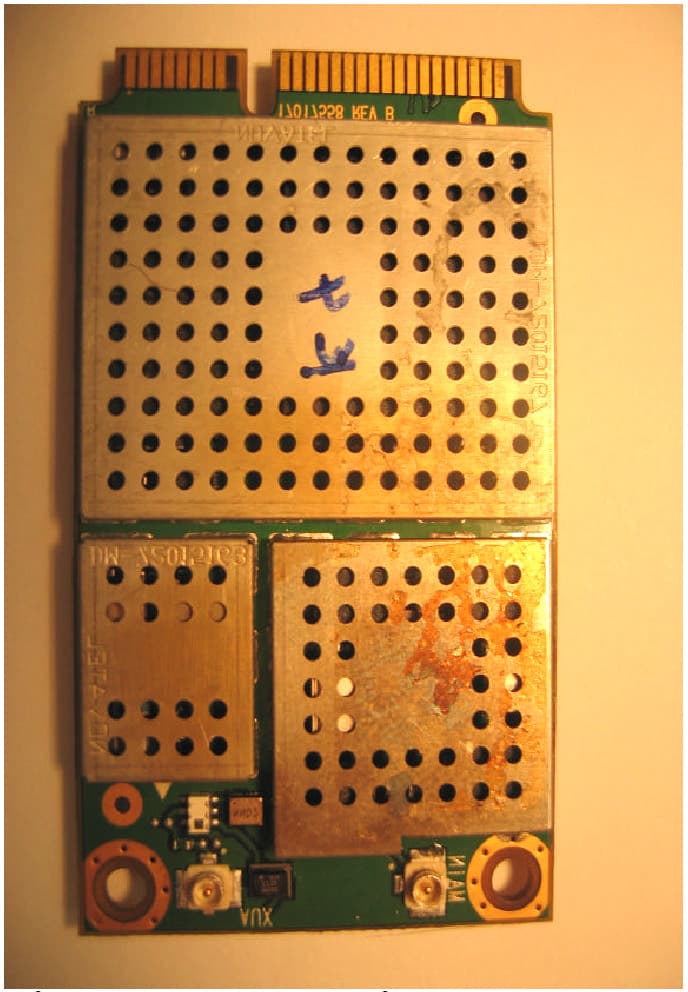
Inside Display Cover Removed Bluetooth Embedded Module location Bluetooth Module Embedded in Display Front Display Cover Right Hand Side Bluetooth Antenna Bluetooth Embedded ModuleFolding AxisDisplay Bluetooth Embedded Module Top-side Bluetooth Modul e (Upper RHS of Display) Bottom-side Bluetooth Module Bluetooth Antenna 802.11a/b/g Embedded Module
Internal Photos
Internal Photo Indicating WLAN Transceiver 802.11a/b/g Embedded Module OQO Model 02 - Embedded Antennas Left-hand side 11 mm 31 mm Area inside cover for embedded antennas. Embedded antennas – seen without external black antenna covers. OQO Model 02 - Embedded Antennas Right-hand side 11 mm 31 mm Area inside cover for embedded antennas. Embedded antennas – seen without external black antenna covers. Embedded Antenna Connector boards Top Side Bottom Side LHS connector board location LHS embedded antenna backside Left-hand side (LHS) Embedded Antenna Connector boards Top Side Bottom Side RHS connector board location RHS embedded antenna backside Right-hand side (RHS) OQO Model 02 – Digital PCB Assemblies Main Logic Board OQO Model 02 – Digital PCB Assemblies Memory Board OQO Model 02 – Digital PCB Assemblies Video / Graphics Board OQO Model 02 – Digital PCB Assemblies Audio / Power Board
RF Exposure Info
© 2007 RF Exposure Lab, LLC This report shall not be reproduced except in full without the written approval of RF Exposure Lab, LLC. 2867 Progress Place, Suite 4D • Escondido, CA 92029 • U.S.A. TEL (760) 737-3131 • FAX (760) 737-9131 http://www.rfexposurelab.com CERTIFICATE OF COMPLIANCE SAR EVALUATION OQO Dates of Test: September 22-23, 2007 583 Shotwell Street Test Report Number: SAR.20070910 San Francisco, CA 94110 Revision A This wireless mobile and/or portable device has been shown to be compliant for localized specific absorption rate (SAR) for uncontrolled environment/general exposure limits specified in ANSI/IEEE Std. C95.1-1999 and had been tested in accordance with the measurement procedures specified in IEEE 1528-2003, OET Bulletin 65 Supp. C, RSS-102 and Safety Code 6 (See test report). I attest to the accuracy of the data. All measurements were performed by myself or were made under my supervision and are correct to the best of my knowledge and belief. I assume full responsibility for the completeness of these measurements and vouch for the qualifications of all persons taking them. RF Exposure Lab, LLC certifies that no party to this application has been denied FCC benefits pursuant to Section 5301 of the Anti-Drug Abuse Act of 1988, 21 U.S.C. 853(a). Jay M. Moulton Vice President Certificate # 2387.01 FCC ID: SHD-A8YWFS IC Certificate: 6026A-A8YWFS Model(s): 02 Test Sample: Pre-Production Unit same as Production Serial No.: 02827370025 Equipment Type: Wireless Computer Classification: Portable Transmitter Next to Body TX Frequency Range: 2412 – 2462 MHz, 5180 – 5320 MHz, 5745 – 5825 MHz Frequency Tolerance: ± 25 ppm Maximum RF Output: 2450 Mhz (b) – 20.3 dBm, 2450 MHz (g) – 15.7 dBm, 5250 MHz – 1 6.8 dBm, 5800 MHz – 17.6 dBm Conducted Signal Modulation: DSSS, OFDM Antenna Type (Length): Internal(OQO P/N FPC-0065) Battery: Standard (OQO P/N FAS-FAS-0081), Extended (OQO P/N FAS-FAS-0082) Battery Pack Accessories Tested: Extended Battery, Steel Case, Holster with Belt Clip, Leather Case with Magnetic Latch, DeskDock Application Type: Certification FCC Rule Parts: Part 15E Industry Canada: RSS-102 FCC ID: SHD-A8YWFS © 2007 RF Exposure Lab, LLC Page 2 of 165 This report shall not be reproduced except in full without the written approval of RF Exposure Lab, LLC. Table of Contents 1. Introduction ...........................................................................................................................3 SAR Definition [5]......................................................................................................................3 2. SAR Measurement Setup .....................................................................................................4 Robotic System .........................................................................................................................4 System Hardware .....................................................................................................................4 System Description ...................................................................................................................4 E-Field Probe ............................................................................................................................5 3. Robot Specifications .............................................................................................................7 4. Probe and Dipole Calibration ................................................................................................8 5. Phantom & Simulating Tissue Specifications........................................................................9 SAM Phantom ...........................................................................................................................9 Brain & Muscle Simulating Mixture Characterization ................................................................9 Device Holder ...........................................................................................................................9 6. Definition of Reference Points.............................................................................................10 Ear Reference Point................................................................................................................10 Device Reference Points ........................................................................................................10 7. Test Configuration Positions ...............................................................................................11 Body Worn Configurations ......................................................................................................11 8. ANSI/IEEE C95.1 – 1999 RF Exposure Limits [2]...............................................................12 Uncontrolled Environment.......................................................................................................12 Controlled Environment .......................................................................................................... 12 9. Measurement Uncertainty ...................................................................................................13 10. System Validation ........................................................................................................... 14 Tissue Verification...................................................................................................................14 Test System Verification ......................................................................................................... 14 11. SAR Test Data Summary................................................................................................15 Procedures Used To Establish Test Signal.............................................................................15 Device Test Condition .....................................................................................…
Text truncated - open the document above for the full version.
Contact Information
Applicant
Bob Hymes(Engineering Program Manager)
Technical Contact
Test Firm
Elliott Laboratories LLCDavid Bare
Technical Specifications
| # | Rule Parts | Frequency Range | Power Output |
|---|---|---|---|
| 1 | 15C | 2.40 GHz - 2.48 GHz | 1.00 mW |
Other Applications from OQO, Inc.
SHD-A7YWFS
Apr 11, 2007Model 02
Equipment Class
PCB - PCS Licensed Transmitter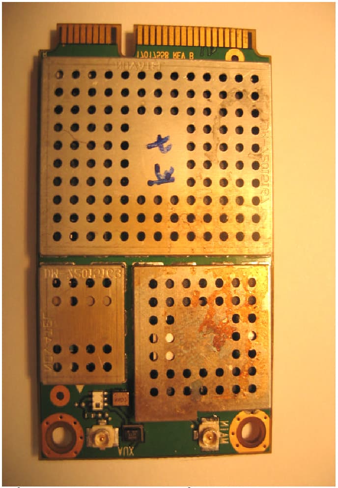
SHD-A6YWFS
Jan 16, 2007Model 02
Equipment Class
DTS - Digital Transmission System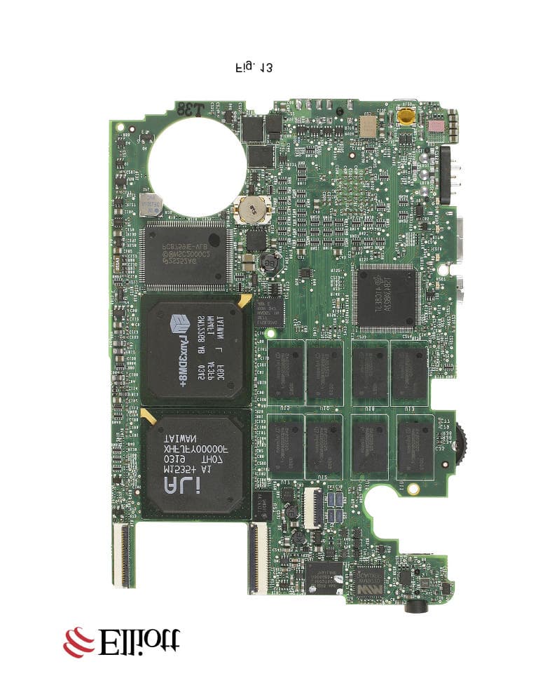
SHD-A4YWFS
Dec 16, 2004Handheld Computer
Equipment Class
DTS - Digital Transmission System