SJ20608137Car equipment unit
Clarion Co., Ltd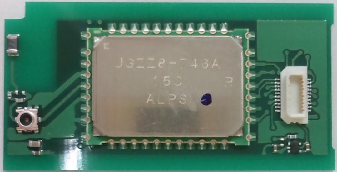
Click to zoom
Application Details
- Equipment Class
- DSS - Part 15 Spread Spectrum Transmitter
- Date of Grant
- Feb 09, 2012
- Application Purpose
- Original Equipment
- Date of Application
- Feb 06, 2012
- Equipment Note
- Car equipment unit
- Frequency Range
- 2402.00000000 - 2480.00000000
- Company
- Clarion Co., Ltd
- Country
- Japan
Documents & Files
Document Text
Text extracted from the exhibit documents filed with the FCC. Open a document above to read the original.
Users Manual
Clarion Co., Ltd. Confidential INSTRUCTION MANUAL OF UGZZ8-X02 1. BLUETOOTH MODULE SPECIFICATION 1-1. PRODUCT NAME UGZZ8-X02 1-2. MANUFACTURER ALPS ELECTRIC 1-3. FEATURES Bluetooth™ Specification V2.0+EDR support Complete type of Bluetooth module, built-in various profile Built-in Link controller, Link Manager Protocol Output Power class2 compliant Type with a chip antenna Full custom package with pwb can be fit to only navigation products made by Clarion Built-in Flash memory(16Mbit), system clock 26MHz(OSC) B to B connector interface 1-4. SPECIFICATION 1-4-1. MECHANICAL SPECIFICATION 1-4-1-1. EXTERNAL DIMENSIONS Refer to the following page. 1-4-1-2. MASS 4.86 [g] 1-4-2. ELECTRIC SPECIFICATION 1-4-2-1. POWER-SUPPLY-VOLTAGE DC +3.1 to +3.6 [V] 1-4-2-2. TEMPERATURE RANGE -40 to +85 [degree C] 1-4-3. RF SPECIFICATION 1-4-3-1. NORMAL TRANSMIT POWER(AVERAGED POWER) -6 to +4 [dBm] 1-4-3-2. REFERENCE SENSITIVITY LEVEL(BER=0.001%) MAX. -70 [dBm] Chip Antenna TAIYO YUDEN AF216M245001 Coaxial Connectors with Switch Murata Manufacturing MM8430-2610 BtoB Connector Matsushita Electric AXK620347Y BLUETOOTH MODULE ALPS ELECTRIC UGZZ8-752A INSTRUCTION MANUAL OF UGZZ8-X02 - 1 / 5 - Clarion Co., Ltd. Confidential 1-5. LABEL INFORMATION 1-5-1. LABEL LAYOUT 1-5-2. CONTENTS OF LABEL 1-6. CONNECTOR PIN ASSIGNMENT NO.PIN NAMENO. 2GND- 1VCCI 4PIO[1] (PTE0)O 3PIO[0] (PTB1)O 6PCM_SYNCO 5PDNO 8GND- 7PCM_OUTO 10UART_CTSI 9UART_RTSO 12UART_TXO 11UART_RXI 14PCM_INI 13PCM_CLKO 16NCI 15NCI 18PIO[2] (PTE5)O 17NCI 20VCCI 19RST#I DESCRIPTION Power Supply 3.3V Ground AV Master Clock Select(44.1kHz=Low, 48kHz=High) PCM_Reset(Active Low), DAC PwrDown(PwrDown Enable=Low) HF/AV Status signal Audio Frame signal AV/HF Output Ground UART_RTS UART_CTS UART_RX UART_TX Audio Clock AV/HF Input NC Power Supply 3.3V NC NC PCM_Mute Reset(Active Low) UGZZ5-X02(Back View) BtoB Connector terminal NO. Label Model: UGZZ8-X02 IC: 419C-0608137 UGZZ8-X02A (Back View) Model NumberRev. Number Clarion Parts Number Lot Number TELEC Mark & ID Company Name FCC ID & IC ID A SJ20608137 001WWDA1606 060-8137-01 Model: UGZZ8-X02 : 419C-0608137 INSTRUCTION MANUAL OF UGZZ8-X02 - 2 / 5 - Clarion Co., Ltd. Confidential 1-7. BLOCK DIAGRAM 2. PROCEDURE TO BUILD IN 2-1. PROCEDURE FOR UGZZ5-XO2 (1)Install UGZZ8-X02 to BT-CAP After install UGZZ5-X02 to BT-CAP (BT-MODULE-AS) Slide to 4 points of Board-guide, and sandwich the module. (2)Connect BT-MODULE-AS to FRONT PCB by BtoB connection Tighten up a screw in order of one to two.After Connect BT-MODULE-AS to FRONT PCB by BtoB connection (FRONT-PCB-AS) SLIDE UGZZ8-X02 BT-CAP FRONT PCB B to B connection BOARD-GUIDE INSTRUCTION MANUAL OF UGZZ8-X02 - 3 / 5 - Clarion Co., Ltd. Confidential (3)Install FRONT-PCB-AS to Navigation-unit Connect FRONT-PCB-AS to Navi-board by FCC cable connection. Tighten up a screw in order of one to four. (4)Install DVD-AS to Navigation-unit (5)Install UPPER-COVER to Navigation-unit (6)Install FRONT-COVER to Navigation-unit (7)Install REAR-COVER to Navigation-unit B to B connection CONDUCTIVE SHEET Chip Antenna position UGZZ8-X02 installation position INSTRUCTION MANUAL OF UGZZ8-X02 - 4 / 5 - Clarion Co., Ltd. Confidential 3. NOITCE -Operation is subject to the following two conditions: (1) this device may not cause interference, and (2) this device must accept any interference, including interference that may cause undesired operation of the device. -Any changes or modifications not expressly approved by the party responsible for compliance could void the user's authority to operate the equipment. -Please note that this users manual should not be provided to end-users. -The following sentence has to be displayed on the outside of the device in which the module is installed: "Contains Transmitter Module FCC ID: SJ20608137", or "Contains FCC ID: SJ20608137" -This equipment complies with FCC RF radiation exposure limits set for an controlled enviornment. -The antenna used for this transmitter must not be co-located or operating in conjunction with any other antenna or transmitter. INSTRUCTION MANUAL OF UGZZ8-X02 - 5 / 5 -
Cover Letter(s)
RF_734_00, Issue 1 Modular Approval Request FCC (per DA 00-1407) FCC ID: SJ20608137 Items to be covered Answer from applicant 1. The modular transmitter must have its own RF shielding. This module has RF shielding with metal case. Refer to external photo. 2. The modular transmitter must have buffered modulation/data inputs (if such inputs are provided) to ensure that the module will comply with Part 15 requirements under conditions of excessive data rates or over-modulation. Using IC, model No. UGZZ8- 752A, has buffered circuit. 3. The modular transmitter must have its own power supply regulation. This Module has its own regulator, part No. IC201 (TK63115HCL-G). Refer to Block diagram. 4. The modular transmitter must comply with the antenna requirements of Section 15.203 and 15.204(c). The antenna must either be permanently attached or employ a “unique” antenna coupler (at all connections between the module and the antenna, including the cable).. A chip antenna is permanently attached to this module. 5. The modular transmitter must be tested in a stand-alone configuration, i.e., the module must not be inside another device during testing. This is intended to demonstrate that the module is capable of complying with Part 15 emission limits regardless of the device into which it is eventually installed. Yes, this testing is performed by stand-alone configuration. 6. The modular transmitter must be labeled with its own FCC ID number, and, if the FCC ID is not visible when the module is installed inside another device, then the outside of the device into which the module is installed must also display a label referring to the enclosed module. This exterior label can use wording such as the following: “Contains Transmitter Module FCC ID: XYZMODEL1” or “Contains FCC ID: XYZMODEL1.” Any similar wording that expresses the same meaning may be used. The Grantee may either provide such a label, an example of which must be included in the application for equipment authorization, or, must provide adequate instructions along with the module which explain this requirement. In the latter case, a copy of these instructions must be included in the application for equipment authorization. The label of this module with its own FCC ID is put on PCB. Exterior label instruction to installer of this module is provided in user manual. 7. The modular transmitter must comply with any specific rule or operating requirements applicable to the transmitter and the manufacturer must provide adequate instructions along with the module to explain any such requirements. A copy of these instructions must be included in the application for equipment authorization. For example, there are very strict operational and timing requirements that must be met before a transmitter is authorized for operation under Section 15.231. For instance, data transmission is prohibited, except for operation under Section 15.231(e), in which case there are separate field strength level and timing requirements. Compliance with these requirements must be assured. Instruction for operational requirements is provided in user manual. 8. The modular transmitter must comply with any applicable RF exposure requirements. For example, FCC Rules in Sections 2.1091, 2.1093 and specific Sections of Part 15, including 15.319(i), 15.407(f), 15.253(f) and 15.255(g), require that Unlicensed PCS, UNII and millimeter wave devices perform routine environmental evaluation for RF Exposure to demonstrate compliance. In addition, spread spectrum transmitters operating under Section 15.247 are required to address RF Exposure compliance in accordance with Section 15.247(b)(4). Modular transmitters approved under other Sections of Part 15, when necessary, may also need to address certain RF Exposure concerns, typically by providing specific installation and operating instructions for users, installers and other interested parties to ensure compliance. This module complies with RF exposure requirements and instruction for users is provided in the user manual. Note: If compliance with one or more of the numbered requirements, listed above, cannot be demonstrated, it may be possible to obtain a “Limited Modular Approval” (LMA). Name and surname of applicant (or authorized representative): Manabu Satomi Date: Feb-2-2012 Signature:
External Photos
Clarion Co., Ltd. Confidential UGZZ8-X02A External Photo 1.Photo 1-1. TOP VIEW 1-2. BOTTOM VIEW UGZZ8-X02 External Photo - 1 / 1 -
ID Label/Location Info
Clarion Co., Ltd. Confidential UGZZ8-X02 Label Information 1. Label layout 2. Contents of Label Model NumberRev. Number Clarion Parts Number Lot Number TELEC Mark & ID Company Name FCC ID & IC ID A SJ20608137 001WWDA1606 060-8137-01 Model: UGZZ8-X02 : 419C-0608137 Model Number Clarion Parts Number Label Lot Number Model: UGZZ8-X02 IC: 419C-0608137 UGZZ8-X02 Label Information - 1 / 1 -
Internal Photos
Clarion Co., Ltd. Confidential UGZZ8-X02 Internal Photo 1.Internal photo Removed shield case Close-up of inside shield case UGZZ8-X02 Internal Photo - 1 / 1 -
RF Exposure Info
RF Exposure Evaluation No.: 11021FCE Page: 2 / 2 5607-2, Nakamuroda-machi, Takasaki-shi, Gunma, 370-3347, Japan Radiofrequency Radiation Exposure Evaluation 15.247(i): Systems operating under the provisions of this section shall be operated in a manner that ensures that the public is not exposed to radio frequency energy levels in excess of the Commission’s guidelines. See § 1.1307(b)(1) of this chapter. 1.1307(b)(1): The appropriate exposure limits in § 1.1310 and 2.1093 of this chapter are generally applicable to all facilities, operations and transmitters regulated by the Commission. 1.1310: The criteria listed in table 1 shall be used to evaluate the environmental impact of human exposure to radiofrequency (RF) radiation as specified in § 1.1307(b). Limit = 1.0 [mW/cm 2 ] at 2.5GHz MPE Calculation: A * B C ** D Limit [mW/cm 2 ] Specified Antenna Gain * Max. RF Output Power at Antenna Terminal [mW] Distance [cm] ** Power Density. [mW/cm 2 ] 1.585 2.951 20 0.000930 1.0 *: Numeric value of antenna gain (2.0dBi). **: The shortest distance between transmitter’s radiating structure and the body of the user or nearby person. This device should be used in separation distance of at least 20 centimeters maintained between transmitter’s radiating structure and the body of the user or nearby persons. Refer to K30306 user manual. Calculation: D = (A * B) / (4 * π * C^2) (1) For a truly worst-case prediction of power density at or near a surface, such as at groundlevel or on a rooftop, 100% reflection of incoming radiation can be assumed, resulting in a potential doubling of predicted field strength and a four-fold increase in power density. In that case Equations (1) can be modified to: D = (2^2)*(A * B) / (4 * π * C^2) (worst-case) Power Density = 0.003722mW/cm 2 MPE Limit = 1.0mW/cm 2 > Power Density in worst-case This means that according to OET Bulletin 65 (Edition 97-01), Supplement C (Edition 01-01), the equipment fulfills the requirements on power density for general population/uncontrolled exposure and therefore fulfills the requirements of 47 CFR Part 15.247(i).
Test Report
Test Report Report No.: 11021FC Page: 2 / 52 Table of Contents Revised Record .....................................................................................................................................................................4 1 Notice..............................................................................................................................................................................5 1.1 General Information .............................................................................................................................................5 1.2 Test Report ...........................................................................................................................................................5 1.3 Test Condition ......................................................................................................................................................5 2 Applicant Information ..................................................................................................................................................6 2.1 Customer Information...........................................................................................................................................6 2.2 Product Description ..............................................................................................................................................6 2.3 Summary of Test and Inspection Result ...............................................................................................................7 3 System Test Configuration ...........................................................................................................................................8 3.1 Justification ..........................................................................................................................................................8 3.2 Operating Modes ..................................................................................................................................................9 3.3 Configuration of Tested System .........................................................................................................................10 3.4 Test Instruments .................................................................................................................................................11 4 Antenna Requirement.................................................................................................................................................12 5 AC Powerline Conducted Emission ...........................................................................................................................13 6 20dB Bandwidth ..........................................................................................................................................................14 6.1 Test Setup ...........................................................................................................................................................14 6.2 Test Results ........................................................................................................................................................14 7 Carrier Frequency Separation ...................................................................................................................................15 7.1 Test Setup ...........................................................................................................................................................15 7.2 Test Results ........................................................................................................................................................15 8 Number of Hopping Frequency .................................................................................................................................17 8.1 Test Setup ...........................................................................................................................................................17 8.2 Test Results ........................................................................................................................................................17 9 Dwell Time ...................................................................................................................................................................18 9.1 Test Setup ...........................................................................................................................................................18 9.2 Test Results ........................................................................................................................................................18 10 Maximum Peak Output Power ..................................................................................................................................21 10.1 Test Setup ...........................................................................................................................................................21 10.2 Test Results ........................................................................................................................................................21 11 Band Edge Compliance...............................................................................................................................................23 11.1 Test Setup ...........................................................................................................................................................23 11.2 Test Results ........................................................................................................................................................23 12 Spurious RF Conducted Emission .................................................................................................................…
Text truncated - open the document above for the full version.
Test Setup Photos
Test Setup Photos (11021FC) Page: 1 / 4 TEST SETUP PHOTOS Applicant : Clarion Co., Ltd. Model No. : UGZZ8-X02 FCC ID : SJ20608137 Test Setup Photos (11021FC) Page: 2 / 4 Photos of Tested EUT Test Setup Photos (11021FC) Page: 3 / 4 Photos of Test Setup Photos of Radiated Measurement Test Setup Photos (11021FC) Page: 4 / 4
Contact Information
Applicant
Noriyuki Komatsu
Technical Contact
Test Firm
TAIYO YUDEN CO., LTD.Katsuaki Nakajima
Technical Specifications
| # | Rule Parts | Frequency Range | Power Output |
|---|---|---|---|
| 1 | 15C | 2.40 GHz - 2.48 GHz | 3.00 mW |
Other Applications from Clarion Co., Ltd

SJ2-CZ305
Dec 28, 2014Car CD/MP3/BT PLAYER
Equipment Class
DSS - Part 15 Spread Spectrum Transmitter
SJ2-CZ505
Dec 22, 2014Car CD/MP3/BT PLAYER
Equipment Class
DSS - Part 15 Spread Spectrum Transmitter
SJ20608136
Mar 27, 2012Car equipment unit
Equipment Class
DSS - Part 15 Spread Spectrum Transmitter
SJ2QY7200
Jun 13, 2010Bluetooth module
Equipment Class
DSS - Part 15 Spread Spectrum Transmitter
SJ2HJZ0095
Jun 19, 2006Bluetooth module
Equipment Class
DSS - Part 15 Spread Spectrum Transmitter