SJC-M1310900 MHz Mote Frequency Hopping System Module
Analog Devices LLC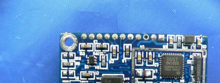
Click to zoom
Application Details
- Equipment Class
- DSS - Part 15 Spread Spectrum Transmitter
- Date of Grant
- Apr 12, 2007
- Application Purpose
- Original Equipment
- Date of Application
- Apr 12, 2007
- Equipment Note
- 900 MHz Mote Frequency Hopping System Module
- Frequency Range
- 903.00500000 - 926.73000000
- Company
- Analog Devices LLC
- Country
- Ireland
Documents & Files
Document Text
Text extracted from the exhibit documents filed with the FCC. Open a document above to read the original.
Users Manual
M1310-1 MOTE DATASHEETDUST NETWORKS™ CONFIDENTIAL Product Description The SmartMesh-XD™ M1310-1 embedded wireless mote uses Time Synchronized Mesh Protocol (TSMP) to enable low- power wireless sensors and actuators with highly reliable wireless mesh networking. The M1310-1 is tailored for use in battery- and line-powered wireless devices for applications that demand proven performance, scalability, and reliability. The M1310-1 uses a 900 MHz radio to achieve more than 200-meter communication distance outdoors, while consuming down to 9 μA in a typical network deployment. The combination of extremely high reliability and low power consumption enables applications that require very low installation cost and low-maintenance, long-term deployments. The standard serial interface of the M1310-1 gives it flexibility to be used in a wide variety of different applications, from industrial process control to security, to lighting. When integrated into a product, the M1310-1 acts like a network interface card (NIC)—it takes a data packet and makes sure that it successfully traverses the network. By isolating the wireless mesh networking protocols from the user, the M1310-1 simplifies the development process and reduces development risk. Key Features Reliable Networking •Uses a Time Synchronized Mesh Protocol (TSMP) for high reliability (>99.9% typical network reliability) •Frequency hopping for interference rejection •Mesh networking for built-in redundancy •Every M1310-1 acts as both an endpoint and a router, increasing network reliability, “mesh-to-the-edge” •Automatic self-organizing mesh is built in Low Power Consumption •Ultra-low power components for long battery life •Network-wide coordination for efficient power usage •Down to 9 μA typical power consumption Efficient Radio •0.4 mW (–3.5 dBm) RF output power •–95 dBm typical receiver sensitivity •Outdoor range >200 m typical Predictable Integration •High-level Data Link Control (HDLC) serial interface with bidirectional flow control •FCC and IC modular intentional radiation certification •Industrial temperature range –40 °C to +85 °C •Supports socket or solder assembly •Rugged design for Class I Division I environments M1310-1 900 MHz Wireless Serial Mote ADVANCED INFORMATION 2DUST NETWORKS™M1310-1 MOTE DATASHEET Contents 1.0Absolute Maximum Ratings .................................................................................... 3 2.0Normal Operating Conditions ................................................................................. 3 3.0Electrical Specifications.......................................................................................... 4 3.1 Application Circuit.............................................................................................4 4.0Radio ...................................................................................................................... 5 4.1 Detailed Radio Specifications...............................................................................5 4.2 Antenna Specifications.......................................................................................5 5.0Pinout..................................................................................................................... 6 6.0Mote Boot Up.......................................................................................................... 6 6.1 Power-on Sequence...........................................................................................6 6.2 Inrush Current..................................................................................................7 6.3 Serial Interface Boot Up.....................................................................................7 7.0Interfaces............................................................................................................... 8 7.1 Timestamps......................................................................................................8 7.2 Status LED Signal..............................................................................................9 7.3 Serial Interface.................................................................................................9 7.3.1 Serial Handshake .................................................................................... 9 7.3.1.1 Serial Port.................................................................................. 9 7.3.1.2 Serial Interface Timing Requirements .......................................... 11 7.3.2 Mote Command Data Types .................................................................... 12 7.3.3 Mote Commands ................................................................................... 13 7.3.3.1 Command 0x80 Serial Payload Sent to Mote Serial ........................ 14 7.3.3.2 Command 0x81 Unacknowledged Serial Payload Received from Mote Serial .......................................................... 14 7.3.3.3 Command 0x82 Acknowledged Serial Payload Received from Mote Serial .......................................................... 14 7.3.3.4 Command 0x84 Time/State Packet.............................................. 15 7.3.3.5 Commands 0x87 and 0x88 Set Parameter Request/Response.......... 15 7.3.3.6 Commands 0x89 and 0x8A Get Parameter Request/Response ......... 16 7.3.3.7 Command 0x8C Mote Information ............................................... 16 7.3.3.8 Command 0x8D Reset Mote ....................................................... 17 7.3.4 Mote Get/Set Command Parameters ........................................................ 17 7.3.4.1 Error Codes.............................................................................. 17 7.3.4.2 Parameter Type 0x01 Network ID................................................ 18 7.3.4.3 Parameter Type 0x02 Mote State ................................................ 18 7.3.4.4 Parameter Type 0x03 Frame Length ............................................ 19 7.3.4.5 Parameter Typ…
Text truncated - open the document above for the full version.
Cover Letter(s)
30695 Huntwood Ave. Hayward, California 94544 www.dustnetworks.com Modular Approval Letter Date: February 22, 2007 The Device, FCC ID: SJC-M1310, is seeking FCC authorization as a modular transmitter. The EUT meets the requirement for modular approval as detailed in FCC Public Notice DA 00-1407. Compliance to each of the requirements is described below: 1. The modular transmitter must have its own RF shielding. => The M1310 has an RF shield on all radio components. 2. The modular transmitter must have buffered modulation/data inputs => All data inputs are buffered. No direct access to the radio is available. 3. The modular transmitter must have its own power supply regulator => The M1310 regulates incoming power. Only 3 volt DC power is required. 4. The modular transmitter must comply with the antenna requirement of section 15.203 and 15.204(c) => The M1310 has an MMCX connector as the only antenna connecter. 5. The modular transmitter must be tested in a stand-alone configuration => Power will be supplied via a test fixture with the device fully exposed. The control for the device is available via a 9-pin serial connector on the test fixture. 6. The modular transmitter must be labeled with its own FCC ID number => The M1310 will have a label on the exposed RF shield. 7. The modular transmitter must comply with any specific rule or operating requirements and the manufacturer must provide adequate instruction along with the module to explain any such requirements => Operation is explained via the datasheet. 8. The modular transmitter must comply with any applicable RF exposure requirements => The M1310 device complies with all applicable RF exposure requirements, including those in DA 00-1407. Sincerely Gordon Charles [email protected]
Cover Letter(s)
30695 Huntwood Ave. Hayward, California 94544 www.dustnetworks.com February 22, 2007 Bay Area Compliance Laboratory Corp. 1274 Anvilwood Ave. Sunnyvale, CA 94089 Phone: 408.732.9162 Fax: 408.732.9164 Re: Confidentiality of FCC Filings Dear Sir/Madam, We, Dust Networks, Inc. request that you file the appropriate paperwork requesting for confidentiality of the data contained in the applications for the following project(s): M1310 Bare Mote – M1310 Specifically, we would like any documents that contain schematics, block diagrams, circuit descriptions, technical specifications, or any other data that can be maintained confidential under FCC rules. Sincerely, Gordon Charles Director of VLSI / Hardware Dust Networks, Inc.
External Photos
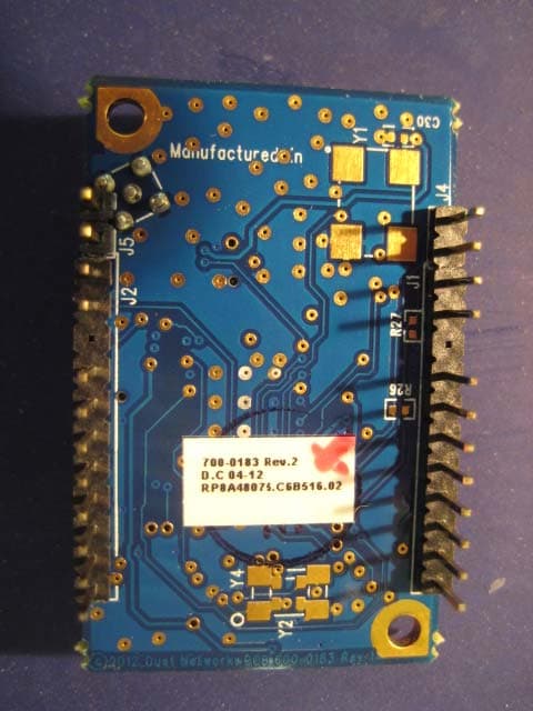
EXHIBIT C - EUT PHOTOGRAPHS EUT – Component View with shielding EUT – Component View without shielding EUT – Solder View EUT – Antenna used for Testing Host – Exterior: Top View Host – Exterior: Bottom View Host – Exterior: Side View 1 EUT Built in Host View
ID Label/Location Info
EXHIBIT A – FCC PRODUCT LABELING AND WARNING STATEMENT FCC ID Label The FCC labels should contain FCC statement in FCC 15.19 paragraph (3). A sample of the statement is presented hereinafter as reference. Also, as per FCC §15.19 a(4) Where a device is constructed in two or more sections connected by wires and marketed together, the statement specified above is required to be affixed only to the main control unit. If the EUT is integrated within another device then a label affixed to the host shall also state, “Contains FCC ID: SJC-M1310” Proposed Label Location on EUT As per FCC §15.19 (b) (4), the label shall not be a stick-on, paper label. The label on these products shall be permanently affixed to the product and shall be readily visible to the purchaser at the time of purchase, as described in Section 2.925(d) of this chapter. "Permanently affixed" means that the label is etched, engraved, stamped, silk-screened, indelibly printed, or otherwise permanently marked on a permanently attached part of the equipment or on a nameplate of metal, plastic, or other material fastened to the equipment by welding, riveting, or a permanent adhesive. The label must be designed to last the expected lifetime of the equipment in the environment in which the equipment may be operated and must not be readily detachable. FCC ID: SJC-M1310 This device complies with Part 15 of the FCC Rules. Operation is subject to the following two conditions: (1) this device may not cause harmful interference, and (2) this device must accept any interference received, including interference that may cause undesired operation. 2.1875" 1.0" FCC ID: SJC-M1310
Internal Photos
EXHIBIT C - EUT PHOTOGRAPHS EUT – Component View with shielding EUT – Component View without shielding EUT – Solder View EUT – Antenna used for Testing Host – Exterior: Top View Host – Exterior: Bottom View Host – Exterior: Side View 1 EUT Built in Host View
Test Report
Note: This test report is for the customer shown above and their specific product only. It may not be duplicated or used in part without prior written consent from Bay Area Compliance Laboratories Corp. This report must not be used by the customer to claim product certification, approval, or endorsement by NVLAP or any agency of the U.S. Governmen t. FCC PART 15.247 MEASUREMENT AND TEST REPORT For Dust Networks, Inc. 30695 Huntwood Ave. Hayward, CA 94544 FCC ID: SJC-M1310 Model: M1310 This Report Concerns: Original Report Equipment Type: 900 MHz Mote Frequency Hopping System Module Test Engineer: Choon Sian Ooi Report Number: R0702152-247 Report Date: 2007-03-29 Reviewed By: VP of Engineering: Hans Mellberg Prepared By: (12) Bay Area Compliance Laboratories Corp. (BACL) 1274 Anvilwood Ave. Sunnyvale, CA 94089 Tel: (408) 732-9162 Fax: (408) 732-9164 Dust Networks Inc. FCC ID: SJC-M1310 Report #: R0702152-247 Page 2 of 47 FCC Part 15.247 Test Report TABLE OF CONTENTS GENERAL INFORMATION.......................................................................................................................................4 PRODUCT DESCRIPTION FOR EQUIPMENT UNDER TEST (EUT) .....................................................................................4 EUT PHOTO.................................................................................................................................................................4 EUT MECHANICAL DESCRIPTION................................................................................................................................4 OBJECTIVE...................................................................................................................................................................5 RELATED SUBMITTAL(S)/GRANT(S).............................................................................................................................5 TEST METHODOLOGY..................................................................................................................................................5 MEASUREMENT UNCERTAINTY....................................................................................................................................5 TEST FACILITY.............................................................................................................................................................5 SYSTEM TEST CONFIGURATION ..........................................................................................................................6 JUSTIFICATION.............................................................................................................................................................6 SPECIAL ACCESSORIES.................................................................................................................................................6 EQUIPMENT MODIFICATIONS.......................................................................................................................................6 POWER SUPPLY............................................................................................................................................................6 INTERFACE PORTS AND CABLING.................................................................................................................................6 LOCAL SUPPORT EQUIPMENT.......................................................................................................................................6 SUMMARY OF TEST RESULTS FOR FCC PART 15............................................................................................7 §15.203 - ANTENNA REQUIREMENT......................................................................................................................8 APPLICABLE STANDARD..............................................................................................................................................8 ANTENNA CONNECTED CONSTRUCTION......................................................................................................................8 §15.205 §15.209 & §15.247 - RADIATED EMISSIONS ...........................................................................................9 APPLICABLE STANDARD: FCC §15.205 RESTRICTED BANDS OF OPERATION...............................................................9 APPLICABLE STANDARD: FCC §15.209 RADIATED EMISSION LIMITS, GENERAL REQUIREMENTS.................................9 APPLICABLE STANDARD: FCC §15.247 RADIATED EMISSION LIMITS.........................................................................10 TEST SETUP................................................................................................................................................................10 TEST EQUIPMENT LIST AND DETAILS.........................................................................................................................10 TEST SETUP DIAGRAM...............................................................................................................................................11 ENVIRONMENTAL CONDITIONS..................................................................................................................................11 TEST PROCEDURE......................................................................................................................................................11 CORRECTED AMPLITUDE & MARGIN CALCULATION.................................................................................................11 SUMMARY OF TEST RESULTS.....................................................................................................................................12 RADIATED EMISSIONS TEST RESULT DATA: MEASURED AT 3 METER........................................................................13 §15.247 (A) (1) - HOPPING CHANNEL SEPARATION .......................................…
Text truncated - open the document above for the full version.
Test Setup Photos
EXHIBIT B – TEST SET UP PHOTOGRAPHS Radiated Spurious Emissions – Front View Radiated Spurious Emissions – Rear View
Contact Information
Applicant
David Bourke(Director of Hardware Engineering)
Test Firm
Bay Area Compliance LaboratoryJohn Chan
Technical Specifications
| # | Rule Parts | Frequency Range | Power Output |
|---|---|---|---|
| 1 | 15C | 903.005 MHz - 926.73 MHz | 800.00 µW |
Other Applications from Analog Devices LLC
SJC-ETERNA1
Jan 17, 2013802.15.4 Wireless Mesh Mote
Equipment Class
DTS - Digital Transmission System
SJC-ETERNA2
Jan 17, 2013802.15.4 Wireless Mesh Mote
Equipment Class
DTS - Digital Transmission System
SJC-M2140
Dec 20, 2007Smart Mesh Wireless Mote
Equipment Class
DTS - Digital Transmission System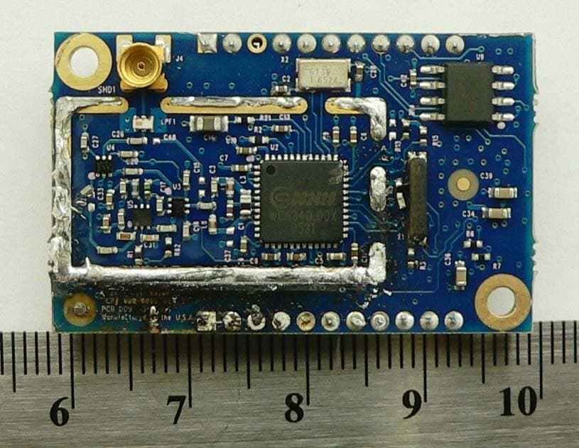
SJC-M2030
Dec 15, 2006SmartMesh M2030 2.4GHz Mote
Equipment Class
DSS - Part 15 Spread Spectrum Transmitter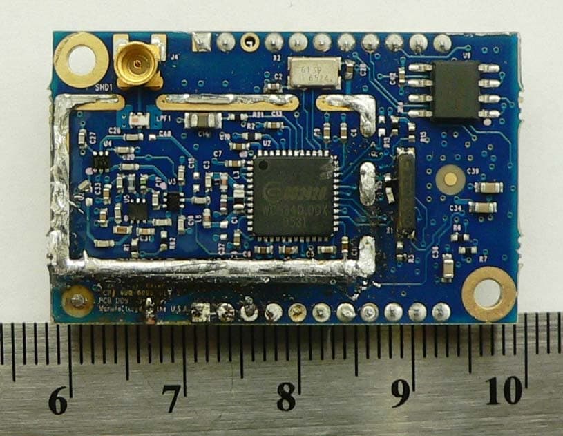
SJC-M2135
Dec 15, 2006SmartMesh M2135 2.4GHz Mote
Equipment Class
DSS - Part 15 Spread Spectrum Transmitter