SLE-AWK-3121BWireless AP/bridge/client
Moxa Inc.
Click to zoom
Application Details
- Equipment Class
- DTS - Digital Transmission System
- Date of Grant
- Oct 05, 2022
- Application Purpose
- Original Equipment
- Date of Application
- Oct 04, 2022
- Equipment Note
- Wireless AP/bridge/client
- Frequency Range
- 2412.00000000 - 2462.00000000
- Company
- Moxa Inc.
- Country
- Taiwan
Documents & Files
Document Text
Text extracted from the exhibit documents filed with the FCC. Open a document above to read the original.
Users Manual
AWK-3121B Se ries QuickInstallation Guide Version 1.4, SEP 2022 Technical Support Contact Information www.moxa.com/support 2022 Moxa Inc. All rights reserved. - 2 - Over view The AWK-3121B wir eless AP/client is the ideal rugged wireless solution for railway onboard/wayside and train-to-ground applications such as CCTV and CBTC communications. It can provide speeds of up to 300 Mbps with IEEE 802.11n technology. The AWK-3121B's can operate at temperatures ranging from -40 to 75°C and meet the requirements of the EN 50155/50121 regulations. Package Checklist The AWK-3121B i s shipped with the following items: •1 AWK-3121B • Quick installation guide (printed) • Product warranty statement If any of these items is missing or damaged, contact your customer service representative for assistance. I nstallation and Configuration B efore installing the AWK-3121B, make sure that all items in the package checklist are included in the box. In addition, you will need access to a notebook computer or PC equipped with an Ethernet port. The AWK-3121Bhas a default IP address that you must use when connecting to the device for the first time. S tep 1: Select the power source The AWK-3121Bca n bepowered by a DC power input. S tep 2: Connect the AWK-3121Bto a notebook or PC S ince the AWK-3121 is provided with the MDI/MDI-X auto-sensing capability of Ethernet connection,you can use either a straight-through cable or crossover cable to connect it to a computer. When the connection between the AWK-3121B and the computer is established, the LED indicator on the AWK-3121B's LAN port lights up. - 3 - Step 3: Set up the computer’s IP address Set an IP address for the computer so that it is on the same subnet as that of the AWK-3121B. Since the AWK-3121B’s default IP address is 192.168.127.253, and the subnet mask is 255.255.255.0, set the IP address of the computer in the 192.168.127.xxx IP range and subnet mask to 255.255.255.0. Step 4: Use the web-based manager to configure the AWK-3121 B Open your computer’s web browser and type http://192.168.127.253 in the address field to access the homepage of the web-b ased manager. Enter the Username and Password to open the AWK-3121B homepage. If you are configuring the AWK-3121 B for the first time, enter the following default Username and Password and click on the Login but ton: Username: admin Password: moxa A TTENTION F or security reasons, we strongly recommend changing the password after first access. To change the password, select Maintenance Password and follow the on -screen instructions. S tep 5: Select the operation mode for the AWK-3121B B y default, the operation mode of the AWK-3121B is set to AP. You can change this setting to Client mode on the Wireless Settings Basic Wireless Settings page. NOTE You must either click the Save Configuration or the Restart button for the configuration changes to be effective. - 4 - Pan el Layout of the AWK-3121B 1. 1A N-typ e antenna port 2. 1B N-type antenna port 3. Model name 4. LEDs 5. 4- pin male M12 A-coded connector for PWR-1 and PWR-2 6. 10/100/1000BaseT(X) 8-pin M12 X-coded female connector for LAN1 7.Grounding screw 8.RJ45 RS-232 console Res et button 9. Wal l Mounting (optional) In mo st applications, wall mounting the AWK-3121Bis the most commonly used method, which makes installation easier as illustrated below: STEP 1: Attach the wall-mountingplates withtheM4 screwsin the accessory package. -5 - STEP 2: Mounting the AWK-3121Bto a wall requires 4 screws. Use the AWK-3121Bdevice, with wall-mountingplates attached, as a guide to mark the correct locations of the 4 screws. The heads of the screws should be 6.0 mm in diameter, and theshafts should be less than3.5 mm in diameter, as shown in the figure at the right. Do not drivethe screws in all the way—leave a space of about 2 mm to allow room for sliding the wall-mount panel between the wall and the screws. NOTETest the screw head and shank size by inserting the screw into one of the keyhole shaped apertures of the wall-mounting plates before driving the screws into the wall. STEP 3: Once the screws are driven into the wall, i nsert the four screw heads through the large opening of the keyhole-shaped aperturesin the wall- mount plates, and then slide the AWK-3121B downwards, as indicated to the right. Tighten the four screws for added stability. DIN-Rail Mounting (Optional) The DIN-rail mounting method is used in industrial or railway application. You will require a DIN-rail attachment plate, which is an optional accessory, to mount the AWK-3121B to a DIN rail. When you attach the DIN- rail attachment plate to the AWK-3121B, make su re that the stiff metal spring is situated towards the top as shown in the following instructions: STEP 1: Attached the DIN-rail mounting plates to the AWK-3121B with the M4 screws in the accessory package. M4 screws specification for Wall Mounting Kit: -6 - WARNING •This equipment is intended to be used in a Restricted Access Location, such as a dedicated computer roomwhere access can only be gained by SERVICE PERSONS or by USERS who have been instructed about the fact that the metal chassis of the equipment is extremely hot and may cause burns. •Access to the equipment should be controlled through the use of a lock and key or a security identification system, controlled by the authority responsible for the location. Only authorized, well-trained professionals should be allowed to access the restricted access location. •Service persons or users mustpay special attention and take special precautions before handling thisequipment. External Metal Parts are Hot! •Useadequate protection before handlingthis device. STEP 2: Insert the top of the DIN rail into the slot justbelow the stiff metal spring. STEP 3: The DIN-rail attachment unit will snap into place as shown in the figure below: To remove the AWK-3121B from the DIN rail, simply reverse Steps 2 and 3. M4 screws specification for DIN-Rail Mounting Kit: -7 - ATTENTION The equipm…
Text truncated - open the document above for the full version.
Cover Letter(s)
Date : September 1, 2022 Federal Communications Commission Authorization and Evaluation Division ATTESTATION FCC ID: SLE‐AWK‐3121B Product: Wireless AP/bridge/client Model: AWK‐3121B We don’t provide any controls or software to allow operation outside the USA frequency band when we sell a product bearing the FCC ID: SLE‐AWK‐3121B. anywhere in the world. Sincerely, ‐‐‐‐‐‐‐‐‐‐‐‐‐‐‐‐‐‐‐‐‐‐‐‐‐‐‐‐‐‐‐‐‐‐‐‐‐‐‐‐‐‐‐‐‐‐‐‐‐‐‐‐‐‐‐‐‐‐‐‐ Penny Weng / Supervisor Moxa Inc.
Cover Letter(s)
FCC, Request for non‐disclosure Date: 21‐Nov‐2018 RF_501, Issue 8 Page 1 of 1 Company Name: Moxa Inc. Address : No. 1111, Heping Rd., Bade Dist. City: Taoyuan City 334004 Country: Taiwan To: Telefication B.V., Dept. FCC TCB Edisonstraat 12A 6902 PK ZEVENAAR The Netherlands Subject: Request for confidentiality FCC ID: SLE‐AWK‐3121B Reference number: ###### Dear FCC TCB, 1. Long‐Term Confidentiality Pursuant to 47 CFR Section 0.459(a) & (b), we hereby requests non‐disclosure and confidential treatment of the following materials submitted in support of FCC certification application: Bill(s) of Material Block Diagrams Operational Description Schematic Diagrams Tune‐up Procedure Above materials contain secrets, proprietary and technical information, which would customarily be guarded from competitors under 47 CFR, section 0.457(d)(2). Disclosure or publication or any portion of this company confidential material to other parties could cause substantial competitive harm and provide unjustified benefits for competitors. 2. Short‐Term Confidentiality (STC) Pursuant to Public Notice DA 04‐1705 of the Commission’s policy, in order to comply with the marketing regulations in 47 CFR §2.803 and the importation rules in 47 CFR §2.1204, a pplicant hereby requests Short‐Term Confidential treatment of the following materials (See notes below): Internal Photos User’s Manual Test Set‐up Photos External Photos Justification: Date: September 1, 2022 Name and signature of applicant: Penny Weng Notes: 1) A document or type of document can only have ONE type of confidentiality! 2) Short‐Term confidentiality is in principle for 45 days from date of grant; it can be extended max 3 times (total time 180 days max.)! The planned date should stated in the RF731 application form. 3) FCC must be informed when marketing begins earlier. 4) Release takes place automatically thus extension must be requested in time. Telefication does not remind you of this! 5) Request for extension or for release must be received by Telefication at least 7 days before date of actual marketing or before expiration of the STC period
Cover Letter(s)
Declaration of Authorization We Name: Moxa Inc. Address: No. 1111, Heping Rd., Bade Dist. City: Taoyuan City 334004 Country: Taiwan Declare that: Name Representative of agent: Stanley Wu (1) Agent Company name: DEKRA Testing and Certification Co., Ltd. Address: No. 26, Huaya 1 st Rd., Guishan Dist. City: Taoyuan City 33341 Country Taiwan is authorized to apply for Certification of the following product(s): Product description: Wireless AP/bridge/client FCC ID: SLE‐AWK‐3121B Model: AWK‐3121B Trademark: MOXA Validity/expiry date: Aug. 16, 2023 on our behalf. Date: September 1, 2022 City: Taoyuan City Name: Penny Weng (2) Function: Supervisor Signature: Notes: (1): Required for FCC application (2): For FCC it must be the Grantee Code “owner” or the authorized agent.
Cover Letter(s)
PROFESSIONAL INSTALLATION ATTESTATION Date: September 1, 2022 FCC ID: SLE‐AWK‐3121B Product: Wireless AP/bridge/client Brand: MOXA Model: AWK‐3121B We, hereby declare that requirements of KDB 353028 D01 Antennas Part 15 Transmitters v01 have been met and shown on the following questions. Further we declare that the info listed below are correct and represent the product in consideration under this filing. Professional installation must be justified. Description: Device is Wireless Router and must need special trained professional in configuring and installing the product, more details please refer to user manual exhibit. Professional installation does not permit use of any antenna with the transmitter; the permitted types of antenna specified as below. Description: Below listed of Antennas has been compliance FCC Rule Part 15 requirement, more details please refer to test reports. No . Manufacturer Part No. Antenna Type Connector Type Max Gain 1 Moxa Inc. ANT‐WDB‐ANM‐0306 Dipole N‐type 3.80 dBi For 2.4GHz 2 Moxa Inc. ANT‐WDB‐ANM‐0502 Dipole N‐type 4.62 dBi For 2.4GHz 3 Moxa Inc. MAT‐WDB‐PA‐NF‐2‐0708 Panel N‐type 7.63 dBi For 2.4GHz 4 Moxa Inc. ANT‐WDB‐PNF‐1011 Panel N‐type 11.0 dBi For 2.4GHz 5 Moxa Inc. ANT‐WDB‐ONM‐0707 Dipole N‐type 7.10 dBi For 2.4GHz 6 Moxa Inc. ANT‐WDB‐ONF‐0709 Dipole N‐type 7.40 dBi For 2.4GHz 7 Moxa Inc. ANT‐WSB‐PNF‐12‐02 Panel N‐type 12.34 dBi For 2.4GHz The applicant should address the following items when justifying professional installation. To qualify for professional installation, please explain why the hardware is not readily available to average consumer. Description: Due to this product and will not be sold directly to the general public through retail store, therefore the hardware is not readily available to average consumer. Marketing — Applicant must ensure device cannot be sold via retail to the general public or by mail order. Description: This product and will not be sold directly to the general public through retail store. It will be sold to authorized dealers or installers only. Applicant must show that device intended use is not for consumers and general public. Description: Device is for industrial/commercial use. Explain what is unique, sophisticated, complex, or specialized about the equipment that REQUIRES it to be installed by a professional installer? Description: The device supports wall mounting which requires to be installed by professional installer. 4. Other professional installation requirements Installation must be controlled. Description: The product will be distributed through controlled distribution channel which has special trained professional to install this product. Installed by licensed professionals. Description: Device sold to dealer who hires installers and need special trained professional in configuring and installing the product. Installation requires special training. Description: The product need special programming, access to keypad, field strength measurements made, so must need special trained professional in configuring and installing the product. If you should have any question(s) regarding this declaration, please don’t hesitate to contact us. Thank you! Sincerely, ‐‐‐‐‐‐‐‐‐‐‐‐‐‐‐‐‐‐‐‐‐‐‐‐‐‐‐‐‐‐‐‐‐‐‐‐‐‐‐‐‐‐‐‐‐‐‐‐‐‐‐‐‐‐‐‐ Penny Weng /Supervisor Moxa Inc.
External Photos
Report No: 2250634R-Product Photos Page: 1 of 27 (1) EUT Photo (2) EUT Photo Report No: 2250634R-Product Photos Page: 2 of 27 (3) EUT Photo (4) EUT Photo Report No: 2250634R-Product Photos Page: 3 of 27 (5) EUT Photo (6) EUT Photo
ID Label/Location Info
MOXA Inc. No. 1111, Heping Rd., Bade Dist., Taoyuan City 334004, Taiwan Tel: +02-8919-1230 FCC ID. : SLE-AWK-3121B FCC ID Label
ID Label/Location Info
MOXA Inc. No. 1111, Heping Rd., Bade Dist., Taoyuan City 334004, Taiwan Tel: +02-8919-1230 FCC ID. : SLE-AWK-3121B The FCC ID and will be placed on the equipment as shown in the photograph below.
Internal Photos
Report No: 2250634R-Product Photos Page: 4 of 27 (7) EUT Photo (8) EUT Photo Report No: 2250634R-Product Photos Page: 5 of 27 (9) EUT Photo (10) EUT Photo Report No: 2250634R-Product Photos Page: 6 of 27 (11) EUT Photo (12) EUT Photo Report No: 2250634R-Product Photos Page: 7 of 27 (13) EUT Photo (14) EUT Photo Report No: 2250634R-Product Photos Page: 8 of 27 (15) EUT Photo (16) EUT Photo Report No: 2250634R-Product Photos Page: 9 of 27 (17) EUT Photo (18) EUT Photo Report No: 2250634R-Product Photos Page: 10 of 27 (19) EUT Photo (20) EUT Photo Report No: 2250634R-Product Photos Page: 11 of 27 (21) EUT Photo (22) EUT Photo RF Chip Report No: 2250634R-Product Photos Page: 12 of 27 (23) EUT Photo (24) EUT Photo Report No: 2250634R-Product Photos Page: 13 of 27 (25) EUT Photo (26) EUT Photo Report No: 2250634R-Product Photos Page: 14 of 27 (27) EUT Photo (28) EUT Photo Report No: 2250634R-Product Photos Page: 15 of 27 (29) EUT Photo (30) EUT Photo Report No: 2250634R-Product Photos Page: 16 of 27 (31) EUT Photo (32) EUT Photo Report No: 2250634R-Product Photos Page: 17 of 27 (33) EUT Photo_MFR: MOXA, M/N: ANT-WDB-ANM-0306 (34) EUT Photo Report No: 2250634R-Product Photos Page: 18 of 27 (35) EUT Photo (36) EUT Photo_ MFR: MOXA, M/N: ANT-WDB-ANM-0502 Report No: 2250634R-Product Photos Page: 19 of 27 (37) EUT Photo (38) EUT Photo Report No: 2250634R-Product Photos Page: 20 of 27 (39) EUT Photo_ MFR: MOXA, M/N: MAT-WDB-PA-NF-2-0708 (40) EUT Photo Report No: 2250634R-Product Photos Page: 21 of 27 (41) EUT Photo (42) EUT Photo_ MFR: MOXA, M/N: ANT-WDB-PNF-1011 Report No: 2250634R-Product Photos Page: 22 of 27 (43) EUT Photo (44) EUT Photo Report No: 2250634R-Product Photos Page: 23 of 27 (45) EUT Photo_ MFR: MOXA, M/N: ANT-WDB-ONM-0707 (46) EUT Photo Report No: 2250634R-Product Photos Page: 24 of 27 (47) EUT Photo (48) EUT Photo_ MFR: MOXA, M/N: ANT-WDB-ONF-0709 Report No: 2250634R-Product Photos Page: 25 of 27 (49) EUT Photo (50) EUT Photo Report No: 2250634R-Product Photos Page: 26 of 27 (51) EUT Photo_ MFR: MOXA, M/N: ANT-WSB-PNF-12-02 (52) EUT Photo Report No: 2250634R-Product Photos Page: 27 of 27 (53) EUT Photo
RF Exposure Info
Report No.: 2250634R-RFUSMPEV02-A Page: 1 of 7 RF Exposure Evaluation Report Product Name : Wireless AP/ Bridge/ Client Model No. : AWK-3121B FCC ID : SLE-AWK-3121B Applicant : Moxa Inc. Address : No. 1111, Heping Rd., Bade Dist., Taoyuan City 334004, Taiwan Date of Receipt : May 21, 2022 Date of Declaration : Aug. 17, 2022 Report No. : 2250634R-RFUSMPEV02-A Report Version : V1.0 The test results relate only to the samples tested. The test results shown in the test report are traceable to the national/international standard through the calibration report of the equipment and evaluated measurement uncertainty herein. This report must not be used to claim product endorsement by TAF or any agency of the government. The test report shall not be reproduced without the written approval of DEKRA Testing and Certification Co., Ltd. Measurement uncertainties evaluated for each testing system and associated connections are given here to provide the system information for reference. Compliance determinations do not take into account measurement uncertainties for each testing system, but are based on the results of the compliance measurement. Report No.: 2250634R-RFUSMPEV02-A Page: 2 of 7 Issued Date: Aug. 17, 2022 Report No.: 2250634R-RFUSMPEV02-A Product Name Wireless AP/ Bridge/ Client Applicant Moxa Inc. Address No. 1111, Heping Rd., Bade Dist., Taoyuan City 334004, Taiwan Manufacturer Moxa Inc. Model No. AWK-3121B FCC ID SLE-AWK-3121B Trade Name MOXA Applicable Standard KDB 447498 D01 v06 Minimum test separation distance ≥ 20 cm For low power devices Test Result Complied Documented By : ( Supervisor / Jinn Chen ) Tested By : ( Senior Engineer / Alan Chen ) Approved By : ( Manager / Tim Sung ) Report No.: 2250634R-RFUSMPEV02-A Page: 3 of 7 Revision History Report No. Ve r s i o n Description Issued Date 2250634R-RFUSMPEV02-A V1.0 Initial issue of report. Aug. 17, 2022 Report No.: 2250634R-RFUSMPEV02-A Page: 4 of 7 1. GENERAL INFORMATION 1.1. EUT Description Product Name Wireless AP/ Bridge/ Client Trade Name MOXA Model No. AWK-3121B FCC ID SLE-AWK-3121B Frequency Range 802.11g: 2412-2462MHz Channel Control Auto Antenna Type Dipole Antenna, Panel Antenna Antenna Gain Refer to the table “Antenna List” 1.2. Antenna List No. Manufacturer Part No. Antenna Type Peak Gain 1 MOXA ANT-WDB-ANM-0306 Dipole Antenna 3.80dBi for 2.4 GHz 2 MOXA ANT-WDB-ANM-0502 Dipole Antenna 4.62dBi for 2.4 GHz 3 MOXA MAT-WDB-PA-NF-2-0708 Panel Antenna 7.63dBi for 2.4 GHz 4 MOXA ANT-WDB-PNF-1011 Panel Antenna 11.0dBi for 2.4 GHz 5 MOXA ANT-WDB-ONM-0707 Dipole Antenna 7.10dBi for 2.4 GHz 6 MOXA ANT-WDB-ONF-0709 Dipole Antenna 7.40dBi for 2.4 GHz 7 MOXA ANT-WSB-PNF-12-02 Panel Antenna 12.34dBi for 2.4 GHz Report No.: 2250634R-RFUSMPEV02-A Pag e: 5 of 7 2.Test Facility USA : FCC Registration Number: TW0033 Canada : CAB Identifier Number: TW3023 / Company Number: 26930 Site Description : Accredited by TAF Accredited Number: 3023 Test Laboratory : DEKRA Testing and Certification Co., Ltd Address : No. 5-22, Ruishukeng Linkou District, New Taipei City, 24451, Taiwan Performed Location : No. 26, Huaya 1st Rd., Guishan Dist.,Taoyuan City 333411, Taiwan, R.O.C. Phone number : +886-3-275-7255 Fax number : +886-3-327-8031 Email address : [email protected] Website: http://www.dekra.com.tw Report No.: 2250634R-RFUSMPEV02-A Page: 6 of 7 3. RF Exposure Evaluation 3.1. Standard Applicable According to KDB 447498 D01 (7.1), A minimum test separation distance ≥ 20 cm is required between the antenna and radiating structures of the device and nearby persons to apply mobile device exposure limits. 3.2. Limits According to FCC 1.1310: The criteria listed in the following table shall be used to evaluate the environment impact of human exposure to radio frequency (RF) radiation as specified in 1.1307(b) LIMITS FOR MAXIMUM PERMISSIBLE EXPOSURE (MPE) Frequency Range (MHz) Electric Field Strength (V/m) Magnetic Field Strength (A/m) Power Density (mW/cm 2 ) Average Time (Minutes) (A) Limits for Occupational/ Control Exposures 300-1500 -- -- F/300 6 1500-100,000 -- -- 5 6 (B) Limits for General Population/ Uncontrolled Exposures 300-1500 -- -- F/1500 6 1500-100,000 -- -- 1 30 F= Frequency in MHz Friis Formula Friis transmission formula: Pd = (Pout*G)/(4*pi*r 2 ) Where Pd = power density in mW/cm 2 Pout = output power to antenna in mW G = gain of antenna in linear scale Pi = 3.1416 R = distance between observation point and center of the radiator in cm Simultaneous transmission MPE test exclusion applies when the sum of the MPE ratios for all simultaneously transmitting antennas incorporated in a host device is ≤ 1.0 Report No.: 2250634R-RFUSMPEV02-A Page: 7 of 7 3.3. Test Result of RF Exposure Evaluation Product : Wireless AP/ Bridge/ Client Test Item : RF Exposure Evaluation WLAN 2.4GHz Peak Gain: 7.40dBi (Dipole Ant no.6) Band Frequency (MHz) Conducted maximum Peak Power (dBm) Antenna Gain (dBi) Power Density at R = 23 cm (mW/cm2) Limit (mW/cm2) 2.4GHz 2462 25.88 7.4 0.3201 1 Note: The conducted output power is refer to report No.: 2250634R-RFUSWL2V01-A from the DEKRA. WLAN 2.4GHz Peak Gain: 12.34dBi (Panel Ant no.7) Band Frequency (MHz) Conducted maximum Peak Power (dBm) Antenna Gain (dBi) Power Density at R = 23 cm (mW/cm2) Limit (mW/cm2) 2.4GHz 2462 25.88 12.34 0.9985 1 Note: The conducted output power is refer to report No.: 2250634R-RFUSWL2V01-A from the DEKRA.
Test Report
Report No.: 2250634R-RFUSWL2V01-A Page : 1 of 82 FCC Test Report Product Name Wireless AP/ Bridge/ Client Model No AWK-3121B FCC ID SLE-AWK-3121B Applicant Moxa Inc. Address No. 1111, Heping Rd., Bade Dist., Taoyuan City 334004, Taiwan Date of Receipt May 21, 2022 Issue Date Aug. 17, 2022 Report No. 2250634R-RFUSWL2V01-A Report Version V1.0 The test results relate only to the samples tested. The test results shown in the test report are traceable to the national/international standard through the calibration report of the equipment and evaluated measurement uncertainty herein. This report must not be used to claim product endorsement by TAF or any agency of the government. The test report shall not be reproduced without the written approval of DEKRA Testing and Certification Co., Ltd. Measurement uncertainties evaluated for each testing system and associated connections are given here to provide the system information for reference. Compliance determinations do not take into account measurement uncertainties for each testing system, but are based on the results of the compliance measurement. Report No.: 2250634R-RFUSWL2V01-A Page : 2 of 82 Test Report Issue Date: Aug. 17, 2022 Report No.: 2250634R-RFUSWL2V01-A Product Name Wireless AP/ Bridge/ Client Applicant Moxa Inc. Address No. 1111, Heping Rd., Bade Dist., Taoyuan City 334004, Taiwan Manufacturer Moxa Inc. Model No. AWK-3121B FCC ID SLE-AWK-3121B EUT Rated Voltage DC 12-48V EUT Test Voltage DC 24V Trade Name MOXA Applicable Standard FCC CFR Title 47 Part 15 Subpart C ANSI C63.4: 2014, ANSI C63.10: 2013 Test Result Complied Documented By : ( Supervisor / Jinn Chen ) Tested By : ( Senior Engineer / Ivan Chuang ) Approved By : ( Senior Engineer / Alan Chen ) Report No.: 2250634R-RFUSWL2V01-A Page : 3 of 82 TABLE OF CONTENTS Description Page 1. GENERAL INFORMATION ..................................................................................................... 6 1.1. EUT Description ............................................................................................................................ 6 1.2. Tested System Details.................................................................................................................... 9 1.3. Configuration of Tested System .................................................................................................... 9 1.4. EUT Exercise Software ................................................................................................................. 9 1.5. Test Facility ................................................................................................................................. 10 1.6. List of Test Item and Equipment ................................................................................................. 11 1.7. Uncertainty .................................................................................................................................. 12 2. Conducted Emission .................................................................................................................. 13 2.1. Test Setup .................................................................................................................................... 13 2.2. Limits .......................................................................................................................................... 13 2.3. Test Procedure ............................................................................................................................. 13 2.4. Test Result of Conducted Emission ............................................................................................. 14 3. Peak Power Output ................................................................................................................... 15 3.1. Test Setup .................................................................................................................................... 15 3.2. Limits .......................................................................................................................................... 15 3.3. Test Procedure ............................................................................................................................. 15 3.4. Test Result of Peak Power Output ............................................................................................... 16 4. Radiated Emission ..................................................................................................................... 28 4.1. Test Setup .................................................................................................................................... 28 4.2. Limits .......................................................................................................................................... 29 4.3. Test Procedure ............................................................................................................................. 30 4.4. Test Result of Radiated Emission ................................................................................................ 32 5. RF antenna conducted test ........................................................................................................ 42 5.1. Test Setup .................................................................................................................................... 42 5.2. Limits .......................................................................................................................................... 42 5.3. Test Procedure ............................................................................................................................. 42 5.4. Test Result of RF antenna conducted test .................................................................................... 43 6. Band Edge ................................................................................................…
Text truncated - open the document above for the full version.
Test Report
Specification 1. Electrical Properties : 1.1 Frequency Range.................. 1.2 Impedance ........................ 1.3 VSWR .............................. 1.4 Return Loss........................ 1.5 Radiation ........................... 1.6 Gain(peak).........................3.5±0.5dBi @ 2.4GHz ~ 2.5GHz 6. 0±1.0dBi@ 4.9GHz ~ 5.825GHz 1.7 Polarization........................Linear; Vertical 1.8 Admitted Power..................1W 1.9 Cable.............................. RG-178 Coaxial Cable 1.10 Connector........................ N-type Plug Standard 2 .4GHz ~ 2.5GHz ;4.9GHz~5.825GHz 50Ω Nominal 2.1 :1Max. -9 dB Max. RF Antenna Assembly Omni-directional 1 Page 9 of 29 4.2 2D patterns 4.2.1 Ant 1 X-Z Plane Y-Z Plane Y Z X Z 11 X-Y Plane Y X Pa ge 11 of 29 4.3 co port & cross port 4.3.1 2400MHz XZ-Phi XZ-Theta 13 Pa ge 12 of 29 XY-Phi XY-Theta 14 P age 13 of 29 4.3.2 2450MHz XZ-Phi XZ-Theta 15 P age 14 of 29 XY-Phi XY-Theta 16 P age 15 of 29 4.3.3 2500MHz XZ-Phi XZ-Theta 17 P age 16 of 29 XY-Phi XY-Theta 18 P age 17 of 29 4.3.4 4900MHz XZ-Phi XZ-Theta 19 P age 18 of 29 XY-Phi XY-Theta 20 P age 19 of 29 4.3.5 5150MHz XZ-Phi XZ-Theta 21 P age 20 of 29 XY-Phi XY-Theta 22 P age 21 of 29 4.3.6 5350MHz XZ-Phi XZ-Theta 23 P age 22 of 29 XY-Phi XY-Theta 24 P age 23 of 29 4.3.7 5550MHz XZ-Phi XZ-Theta 25 P age 24 of 29 XY-Phi XY-Theta 26 P age 25 of 29 4.3.8 5750MHz XZ-Phi XZ-Theta 27 P age 26 of 29 XY-Phi XY-Theta 28 P age 27 of 29 4.3.9 5825MHz XZ-Phi XZ-Theta 29 P age 28 of 29 XY-Phi XY-Theta 30
Test Report
Electrical Specification: Frequency 2.4~2.5/5.0~5.8GHz Part Number Polarization Vertical V.S.W.R ≦2.0 Impedance 50Ω Gain 2.4-5dBi/5.8-2dBi Power handling 2W Front to back ratio NO HPBW/horizontal 360° HPBW/vertical 65° Rated Wind Operating temperature -40°C~+80°C Humidity 100% Storage Temp and Humidity -40°C~+80°C IP rating IP67 Vertical Frequency(MHz) 2400MHz Maximum Gain(dB) 3.57dB 42.19deg Minimum Gain(dB) -16.34dB-17.14deg Average Gain(dB) -1.46dB Horizontal Frequency(MHz) 2400MHz Maximum Gain(dB) 3.57dB -68.57deg Minimum Gain(dB) 0.76dB 129.38deg Average Gain(dB) 2.09dB Vertical Frequency(MHz) 2450MHz Maximum Gain(dB) 3.75dB 25.31deg Minimum Gain(dB) -19.65dB-165.71deg Average Gain(dB) -1.56dB Horizontal Frequency(MHz) 2450MHz Maximum Gain(dB) 3.75dB -68.57deg Minimum Gain(dB) 1.05dB 261.56deg Average Gain(dB) 2.18dB Vertical Frequency(MHz) 2500MHz Maximum Gain(dB) 3.74dB 25.31deg Minimum Gain(dB) -16.98dB-165.71deg Average Gain(dB) -1.41dB Horizontal Frequency(MHz) 2500MHz Maximum Gain(dB) 3.74dB -71.43deg Minimum Gain(dB) 1.08dB 104.06deg Average Gain(dB) 2.23dB Vertical Frequency(MHz) 2400MHz Maximum Gain(dB) 4.62dB 50.62deg Minimum Gain(dB) -10.70dB-31.43deg Average Gain(dB) -1.53dB Horizontal Frequency(MHz) 2400MHz Maximum Gain(dB) 4.62dB -77.14deg Minimum Gain(dB) 0.60dB 112.50deg Average Gain(dB) 2.76dB Vertical Frequency(MHz) 2450MHz Maximum Gain(dB) 4.27dB 160.31deg Minimum Gain(dB) -16.07dB20.0deg Average Gain(dB) -2.12dB Horizontal Frequency(MHz) 2450MHz Maximum Gain(dB) 4.27dB -74.29deg Minimum Gain(dB) -0.16dB340.31deg Average Gain(dB) 2.49dB Vertical Frequency(MHz) 2500MHz Maximum Gain(dB) 4.31dB 160.31deg Minimum Gain(dB) -19.87dB20.0deg Average Gain(dB) -2.40dB Horizontal Frequency(MHz) 2500MHz Maximum …
Text truncated - open the document above for the full version.
Contact Information
Applicant
Steve Wang(Vice President)
Technical Contact
DEKRA Testing and Certification Co., Ltd.Ashley Chen
[email protected]+88632757255
No. 26, Hwaya 1st Road., Guishan District · Taiwan
Non-Technical Contact
DEKRA Testing and Certification Co., Ltd.Ashley Chen
[email protected]+88632757255
Test Firm
DEKRA TESTING AND CERTIFICATION CO., LTD. LinKouMirenda Liao
Technical Specifications
| # | Rule Parts | Frequency Range | Power Output |
|---|---|---|---|
| 1 | 15C | 2.41 GHz - 2.46 GHz | 390.00 mW |
Other Applications from Moxa Inc.

SLE-AWK3262A
Oct 08, 2024Wireless AP/bridge/client
Equipment Class
DTS - Digital Transmission System
SLE-AWK4262A
Oct 07, 2024Wireless AP/bridge/client
Equipment Class
DTS - Digital Transmission System
SLE-AWK1160
Mar 31, 2024Industrial Wi-Fi 6 wireless access points / Industrial Wi-Fi 6 wireless clients
Equipment Class
DTS - Digital Transmission System
SLE-WM-AN-AT-01
Jul 30, 2020Industrial WiFi module
Equipment Class
NII - Unlicensed National Information Infrastructure TX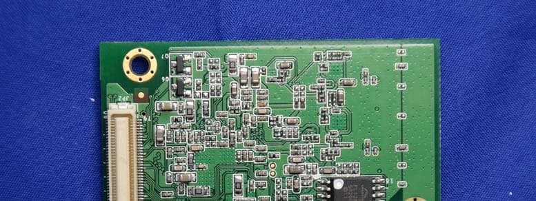
SLE-WAPN008
Aug 24, 2015MOXA IEEE 802.11 a/b/g/n
Equipment Class
DTS - Digital Transmission System