SLEZ2150INDUSTRIAL ZIGBEE MODULE
Moxa Inc.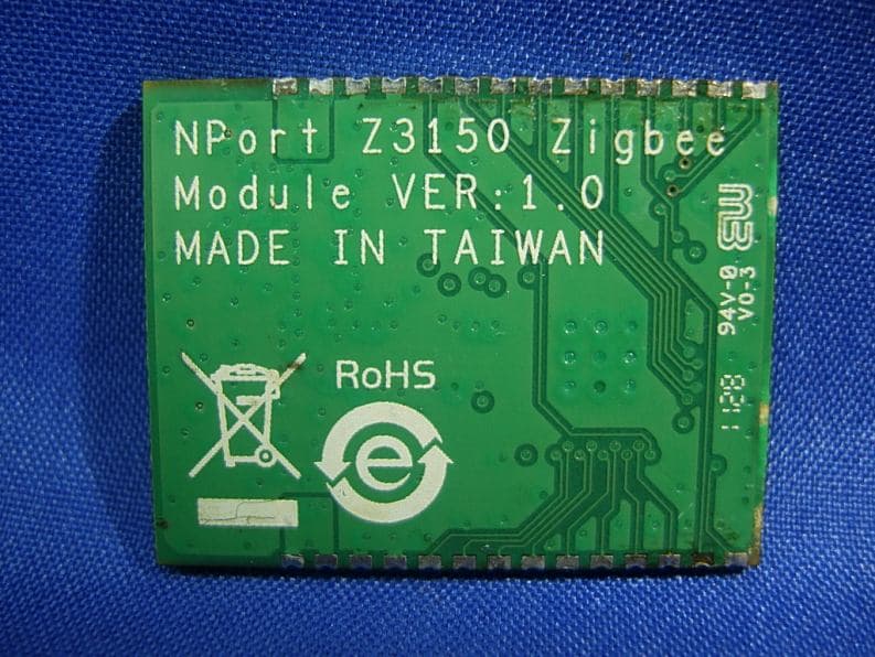
Click to zoom
Application Details
- Equipment Class
- DTS - Digital Transmission System
- Date of Grant
- Dec 27, 2011
- Application Purpose
- Original Equipment
- Date of Application
- Dec 27, 2011
- Equipment Note
- INDUSTRIAL ZIGBEE MODULE
- Frequency Range
- 2405.00000000 - 2475.00000000
- Company
- Moxa Inc.
- Country
- Taiwan
Documents & Files
Document Text
Text extracted from the exhibit documents filed with the FCC. Open a document above to read the original.
Users Manual
Moxa Industrial ZigBee Module SLEZ2150 User’s Manual First Edition, November 2011 www.moxa.com/product © 2011 Moxa Inc. All rights reserved. Moxa Industrial ZigBee Module SLEZ2150 User’s Manual The software described in this manual is furnished under a license agreement and may be used only in accordance with the terms of that agreement. Copyright Notice © 2011 Moxa Inc. All rights reserved. Trademarks The MOXA logo is a registered trademark of Moxa Inc. All other trademarks or registered marks in this manual belong to their respective manufacturers. Disclaimer Information in this document is subject to change without notice and does not represent a commitment on the part of Moxa. Moxa provides this document as is, without warranty of any kind, either expressed or implied, including, but not limited to, its particular purpose. Moxa reserves the right to make improvements and/or changes to this manual, or to the products and/or the programs described in this manual, at any time. Information provided in this manual is intended to be accurate and reliable. However, Moxa assumes no responsibility for its use, or for any infringements on the rights of third parties that may result from its use. This product might include unintentional technical or typographical errors. Changes are periodically made to the information herein to correct such errors, and these changes are incorporated into new editions of the publication. Technical Support Contact Information www.moxa.com/support Moxa Americas Toll-free: 1-888-669-2872 Tel: +1-714-528-6777 Fax: +1-714-528-6778 Moxa China (Shanghai office) Toll-free: 800-820-5036 Tel: +86-21-5258-9955 Fax: +86-21-5258-5505 Moxa Europe Tel: +49-89-3 70 03 99-0 Fax: +49-89-3 70 03 99-99 Moxa Asia-Pacific Tel: +886-2-8919-1230 Fax: +886-2-8919-1231 Table of Contents 1. Introduction ...................................................................................................................................... 1-1 Overview ........................................................................................................................................... 1-2 Features ............................................................................................................................................ 1-2 Specifications ..................................................................................................................................... 1-2 2. Gettting Started ................................................................................................................................ 2-1 Module Layout .................................................................................................................................... 2-2 Block Diagram .................................................................................................................................... 2-2 Connector Locations ............................................................................................................................ 2-3 Hardware Installation .......................................................................................................................... 2-3 Software Installation ........................................................................................................................... 2-3 A. Regulatory Statements...................................................................................................................... A- 1 1 1. Introduction The following topics are covered in this chapter: Overview Features Specifications SLEZ2150 User's Manual Introduction 1-2 Overview The SLEZ2150 module is designed to provide ZigBee communication for all ZigBee-device-based systems. It communicates via the standard 802.15.4 protocols. The SLEZ2150 uses the CC2530 chipset from TI. This module is connected to the main board through SMA connector and special circuitry to allow for compatibility with 3.3V PCI signaling. Features • Instant connection of any serial device to Zigbee network • Secure data access with AES Specifications RF Data Rate 250 kbps Outdoor/RF Line-of-Sight Range 130 m Transmit Power 4.5 dBm (Max) Receiver Sensitivity (1% PER) -96 dBm Adjustable Power Yes Frequency Band 2.4 GHz Interference Immunity DSSS (Direct Sequence Spread Spectrum) PAN ID 0x0000~0xFFFF Node ID 0x0000~0xFFFF RF Channel 11-25 (15 channels) Device Type Coordinator, Router, End Device Network Topology Star, Mesh, Cluster Security ZigBee Certified Operating Temperature -40° C to +75° C Power Requirement 3.3 V +/-10% Information for OEMs and Integrators The following statement must be included with all versions of this document supplied to an OEM or integrator, but should not be distributed to the end user. 1)This device is intended for OEM integrators only. 2)Please See the full Grant of Equipment document for other restrictions. 2 2. Getting Started This chapter covers the module layout, and block diagram, hardware installation of the SLEZ2150. Software installation is covered in the next chapter. Module Layout Block Diagram Connector Locations Hardware Installation Software Installation SLEZ2150 User's Manual Gettting Started 2-2 Module Layout Block Diagram SLEZ2150 User's Manual Gettting Started 2-3 Connector Locations Hardware Installation The ZigBee Module can be installed into all MOXA Zigbee system board series. Steps for Installation 1. Attach the WLAN antenna to connector UI 2. Let ZigBee Module connect to NPort Z2150/3150 3. Screw on the ZigBee Module Software Installation After physically installing the SLEZ2150, the module will be recognized on the new system board after the following steps. Steps for Installation 1. Apply power to the system board. A A. Regulatory Statements Federal Communications Commission Interference Statement This equipment has been tested and found to comply with the limits for a Class B digital device, pursuant to part 15 of the FCC Rules. These limits are designed t…
Text truncated - open the document above for the full version.
Cover Letter(s)
Moxa Inc. FCC ID.: SLEZ2150 Fl.4. No.135. Lane 235, Baoqiao Rd. Xindian Dist, New Taipei City, Taiwan. Tel : +886-2-89191230 Federal Communications Commission Nov. 23 , 2011 Authorization and Evaluation Division ATTESTATION FCC ID: SLEZ2150 Product: Industrial ZigBee module Model: NPort Z3150 ZigBee Module We don't provide any controls or software to allow operation outside the USA frequency band when we sell this product in USA. Sincerely, CHAO HUNG-CHENG / Director Moxa Inc.
Cover Letter(s)
Moxa Inc. FCC ID.: SLEZ2150 Fl.4. No.135. Lane 235, Baoqiao Rd. Xindian Dist, New Taipei City, Taiwan. Tel : +886-2-89191230 Moxa Inc. Fl.4. No.135. Lane 235, Baoqiao Rd. Xindian Dist, New Taipei City, Taiwan. Tel : +886-2-89191230 Fax: +886-2-89191231 Federal Communications Commission Nov. 23 , 2011 Authorization and Evaluation Division Confidentiality Request Pursuant to Sections 0.457 and 0.459 of the Commission’s Rules, the Applicant Hereby requests confidential treatment of information accompanying this Application As outlined below: Schematics: (NPort Z3150 ZigBee Module) Schem Block Diagram : (NPort Z3150 ZigBee Module) BlkDia The above materials contain trade secrets and proprietary information not customarily Released to the public. The public disclosure of these matters might be harmful to the Applicant and provide unjustified benefits to its competitors. The Applicant understands that pursuant to Rule 0.457, disclosure of this Application and all accompanying documentation will not be made before the date of the Grant for this application. Sincerely, CHAO HUNG-CHENG / Director Moxa Inc.
Cover Letter(s)
RF_160, Issue 02 Moxa Inc. Declaration of Authorization We Name: Moxa Inc. Address: Fl.4. No.135. Lane 235, Baoqiao Rd. Xindian Dist, New Taipei City, Taiwan. City: Taipei ............................................................ . ........................ Country: Taiwan. .................................................................. . ............ Declare that: Name Representative of agent: Gene Chang (1) Agent Company name: QuieTek Corp. Address: Fl.2, No.345, Xin-hu 2 nd Rd., Nei-hu District City: Taipei Country Taiwan is authorized to apply for Certification of the following product(s): Product description: Industrial ZigBee module Type designation: NPort Z3150 ZigBee Module Trademark: Moxa on our behalf. Date: ...... 2011/11/23 ... .. City: ...... Taipei ...... .. Name: ...... CHAO HUNG-CHENG ...... .. (2) Function: Director Signature: Notes: (1): Required for FCC application (2): For FCC it must be the Grantee Code “owner” or the authorized agent.
Cover Letter(s)
Modular Approval Request FCC (FCC Part 15 Section 15.212 Modular transmitters) FCC ID: SLEZ2150 Items to be covered Answer from applicant 1. The modular transmitter must have its own RF shielding. The modular transmitter have its own RF shielding. 2. The modular transmitter must have buffered modulation/data inputs (if such inputs are provided) to ensure that the module will comply with Part 15 requirements under conditions of excessive data rates or over-modulation. The EUT has buffered data inputs, it is integrated in chip CC2530 3. The modular transmitter must have its own power supply regulation. The EUT hasn’t power supply regulation. 4. The modular transmitter must comply with the antenna requirements of Section 15.203 and 15.204(c). The antenna must either be permanently attached or employ a “unique” antenna coupler (at all connections between the module and the antenna, including the cable).. The modular transmitter with reverse SMA connector antenna and complies the requirements of Section 15.203 and 15.204(c). 5. The modular transmitter must be tested in a stand-alone configuration, i.e., the module must not be inside another device during testing. This is intended to demonstrate that the module is capable of complying with Part 15 emission limits regardless of the device into which it is eventually installed. The modular transmitter is tested in a stand-alone configuration. 6. The modular transmitter must be labeled with its own FCC ID number, and, if the FCC ID is not visible when the module is installed inside another device, then the outside of the device into which the module is installed must also display a label referring to the enclosed module. This exterior label can use wording such as the following: “Contains Transmitter Module FCC ID: XYZMODEL1” or “Contains FCC ID: XYZMODEL1.” Any similar wording that expresses the same meaning may be used. The Grantee may either provide such a label, an example of which must be included in the application for equipment authorization, or, must provide adequate instructions along with the module which explain this requirement. In the latter case, a copy of these instructions must be included in the application for equipment authorization. The modular transmitter is labelled with its own FCC ID number. 7. The modular transmitter must comply with any specific rule or operating requirements applicable to the transmitter and the manufacturer must provide adequate instructions along with the module to explain any such requirements. A copy of these instructions must be included in the application for equipment authorization. For example, there are very strict operational and timing requirements that must be met before a transmitter is authorized for operation under Section 15.231. For instance, data transmission is prohibited, except for operation under Section 15.231(e), in which case there are separate field strength level and timing requirements. Compliance with these requirements must be assured. The modular transmitter complies with any specific rule or operating requirements applicable to the transmitter and the manufacturer must provide adequate instructions along with the module to explain any such requirements. 8. The modular transmitter must comply with any applicable RF exposure requirements. For example, FCC Rules in Sections 2.1091, 2.1093 and specific Sections of Part 15, including 15.319(i), 15.407(f), 15.253(f) and 15.255(g), require that Unlicensed PCS, UNII and millimeter wave devices perform routine environmental evaluation for RF Exposure to demonstrate compliance. In addition, spread spectrum transmitters operating under Section 15.247 are required to address RF Exposure compliance in accordance with Section 15.247(b)(4). Modular transmitters approved under other Sections of Part 15, when necessary, may also need to address certain RF Exposure concerns, typically by providing specific installation and operating instructions for users, installers and other interested parties to ensure compliance. The modular transmitter complies with any applicable RF exposure requirements. Note: If compliance with one or more of the numbered requirements, listed above, cannot be demonstrated, it may be possible to obtain a “Limited Modular Approval” (LMA). Name and surname of applicant (or authorized representative): _ CHAO HUNG-CHENG ____ Date: _Nov. 23, 2011___ Signature: ___________________________
External Photos
Report No.: 117349R-RFUSP28V01 Page : 1 of 9 Attachment 2 : EUT Detailed Photographs (1) EUT Photo (2) EUT Photo
ID Label/Location Info
Moxa Inc. FCC ID.: SLEZ2150 Fl.4. No.135. Lane 235, Baoqiao Rd. Xindian Dist, New Taipei City, Taiwan. Tel : +886-2-89191230 FCC ID Label
ID Label/Location Info
Moxa Inc. FCC ID.: SLEZ2150 Fl.4. No.135. Lane 235, Baoqiao Rd. Xindian Dist, New Taipei City, Taiwan. Tel : +886-2-89191230 The FCC ID Label will be placed on the equipment as shown in the photograph below.
Internal Photos
Report No.: 117349R-RFUSP28V01 Page : 2 of 4 (3) EUT Photo (4) EUT Photo Report No.: 117349R-RFUSP28V01 Page : 3 of 4 (5) EUT Photo (6) EUT Photo Report No.: 117349R-RFUSP28V01 Page : 4 of 4 (7) EUT Photo
Operational Description
Report No. 117349R-RFUSP28V01 Page : 7 of 49 1.2. Operational Description The EUT is a Industrial ZigBee module, The Number of the channels is 15 in 2405~2475MHz, The device adapts the OQPSK modulation, The Antenna is Dipole Antenna. IEEE Std 802.15.4 defines the physical layer (PHY) and medium access control (MAC) sublayer specifications for low-data-rate wireless connectivity with fixed, portable, and moving devices with no battery or very limited battery consumption requirements typically operating in the personal operating space (POS) of 10 m. ZigBee applications include: • Home and office automation • Industrial automation • Medical monitoring • Low-power sensors • HVAC control • Plus many other control and monitoring uses
RF Exposure Info
Report No. 117349R-RFUSP28V01 Page: 1 of 3 RF Exposure Evaluation declaration Product Name Industrial ZigBee module Model No. NPort Z3150 ZigBee Module FCC ID SLEZ2150 Applicant Moxa Inc. Address Fl.4. No.135. Lane 235, Baoqiao Rd. Xindian Dist, New Taipei City, Taiwan. Date of Receipt July 21, 2011 Date of Declaration Aug. 15, 2011 Report No. 117349R-RFUSP28V01 The declaration results relate only to the samples calculated. The declaration shall not be reproduced except in full without the written approval of QuieTek Corporation. This report must not be used to claim product endorsement by NVLAP any agency of the U.S. Government Report No. 117349R-RFUSP28V01 Page: 2 of 3 1. RF Exposure Evaluation 1.1. Limits According to FCC 1.1310: The criteria listed in the following table shall be used to evaluate the environment impact of human exposure to radio frequency (RF) radiation as specified in 1.1307(b) LIMITS FOR MAXIMUM PERMISSIBLE EXPOSURE (MPE) Frequency Range (MHz) Electric Field Strength (V/m) Magnetic Field Strength (A/m) Power Density (mW/cm 2 ) Average Time (Minutes) (A) Limits for Occupational/ Control Exposures 300-1500 -- -- F/300 6 1500-100,000 -- -- 5 6 (B) Limits for General Population/ Uncontrolled Exposures 300-1500 -- -- F/1500 6 1500-100,000 -- -- 1 30 F= Frequency in MHz Friis Formula Friis transmission formula: Pd = (Pout*G)/(4*pi*r 2 ) Where Pd = power density in mW/cm 2 Pout = output power to antenna in mW G = gain of antenna in linear scale Pi = 3.1416 R = distance between observation point and center of the radiator in cm Pd id the limit of MPE, 1 mW/cm 2 . If we know the maximum gain of the antenna and the total power input to the antenna, through the calculation, we will know the distance r where the MPE limit is reached. 1.2. Test Procedure Software provided by client enabled the EUT to transmit and receive data at lowest, middle and highest channel individually. The temperature and related humidity: 18°Cand 78% RH. Report No. 117349R-RFUSP28V01 Page: 3 of 3 1.3. Test Result of RF Exposure Evaluation Product : Industrial ZigBee module Test Item : RF Exposure Evaluation Test Site : No.3 OATS Antenna Gain Antenna Gain: The maximum Gain measured in fully anechoic chamber is 2.9 dBi in logarithm scale. 1Mbps (GFSK) Output Power Into Antenna & RF Exposure Evaluation Distance (2.9dBi): Channel Frequency (MHz) Output Power to Antenna (mW) Power Density at R = 20 cm (mW/cm2) 01 2405.00 1.9275 0.000748 08 2440.00 1.8197 0.000706 15 2475.00 1.7179 0.000666 The distance r (4 th column) calculated from the Fries transmission formula is far shorter than 20 cm separation requirement.
Test Report
Report No. 117349R-RFUSP28V01 Page : 1 of 49 Test Report Product Name Industrial ZigBee module Model No NPort Z3150 ZigBee Module FCC ID. SLEZ2150 Applicant Moxa Inc. Address Fl.4. No.135. Lane 235, Baoqiao Rd. Xindian Dist, New Taipei City, Taiwan. Date of Receipt July 21, 2011 Issue Date Aug. 15, 2011 Report No. 117349R-RFUSP28V01 Report Version V1.0 The test results relate only to the samples tested. The test report shall not be reproduced except in full without the written approval of QuieTek Corporation. This report must not be used to claim product endorsement by NVLAP any agency of the U.S. Government Report No. 117349R-RFUSP28V01 Page : 2 of 49 Test Report Certification Issue Date: Aug. 15, 2011 Report No.: 117349R-RFUSP28V01 Product Name Industrial ZigBee module Applicant Moxa Inc. Address Fl.4. No.135. Lane 235, Baoqiao Rd. Xindian Dist, New Taipei City, Taiwan. Manufacturer Moxa Inc. Model No. NPort Z3150 ZigBee Module EUT Rated Voltage DC 3.3V EUT Test Voltage AC 120V/ 60Hz Trade Name Moxa Applicable Standard FCC CFR Title 47 Part 15 Subpart C: 2010 ANSI C63.4: 2009 Test Result Complied The test results relate only to the samples tested. The test report shall not be reproduced except in full without the written approval of QuieTek Corporation. This report must not be used to claim product endorsement by NVLAP any agency of the U.S. Government Documented By : (Senior Adm. Specialist / Rita Huang) Tested By : ( Engineer / Sabrina Tsai ) Approved By : ( Manager / Vincent Lin) Accredited by NIST (NVLAP) NVLAP Lab Code: 200533-0 Report No. 117349R-RFUSP28V01 Page : 3 of 49 TABLE OF CONTENTS Description Page 1. GENERAL INFORMATION .....................................................................................................5 1.1. EUT Description............................................................................................................................5 1.2. Operational Description ................................................................................................................7 1.3. Tested System Details....................................................................................................................8 1.4. Configuration of Tested System ....................................................................................................8 1.5. EUT Exercise Software .................................................................................................................9 1.6. Test Facility .................................................................................................................................10 2. Conducted Emission.................................................................................................................. 11 2.1. Test Equipment............................................................................................................................11 2.2. Test Setup ....................................................................................................................................11 2.3. Limits ..........................................................................................................................................12 2.4. Test Procedure .............................................................................................................................12 2.5. Uncertainty ..................................................................................................................................12 2.6. Test Result of Conducted Emission.............................................................................................13 3. Peak Power Output ...................................................................................................................15 3.1. Test Equipment............................................................................................................................15 3.2. Test Setup ....................................................................................................................................15 3.3. Limits ..........................................................................................................................................15 3.4. Test Procedure .............................................................................................................................15 3.5. Uncertainty ..................................................................................................................................15 3.6. Test Result of Peak Power Output...............................................................................................16 4. Radiated Emission .....................................................................................................................17 4.1. Test Equipment............................................................................................................................17 4.2. Test Setup ....................................................................................................................................18 4.3. Limits ..........................................................................................................................................19 4.4. Test Procedure .............................................................................................................................19 4.5. Uncertainty ..................................................................................................................................19 4.6. Test Result of Radiated Emission................................................................................................20 5. RF antenna conducted test........................................................................................................24 5.1. Test Equipment............................................................................................................................24 5.2. Test Setup ...…
Text truncated - open the document above for the full version.
Test Setup Photos
Report No.: 117349R-RFUSP28V01 Page : 1 of 3 Attachment 1: EUT Test Setup Photographs Front View of Conducted Test Back View of Conducted Test Report No.: 117349R-RFUSP28V01 Page : 2 of 3 Front View of Radiated Test Back View of Radiated Test Report No.: 117349R-RFUSP28V01 Page : 3 of 3 Front View of Radiated Test (Horn) Back View of Radiated Test (Horn)
Contact Information
Applicant
James Wu(Vice President)
Test Firm
DEKRA Testing and Certification Co., Ltd.Sky Hsu
Technical Specifications
| # | Rule Parts | Frequency Range | Power Output |
|---|---|---|---|
| 1 | 15C | 2.40 GHz - 2.48 GHz | 2.00 mW |
Other Applications from Moxa Inc.

SLE-AWK3262A
Oct 08, 2024Wireless AP/bridge/client
Equipment Class
DTS - Digital Transmission System
SLE-AWK4262A
Oct 07, 2024Wireless AP/bridge/client
Equipment Class
DTS - Digital Transmission System
SLE-AWK1160
Mar 31, 2024Industrial Wi-Fi 6 wireless access points / Industrial Wi-Fi 6 wireless clients
Equipment Class
DTS - Digital Transmission System
SLE-AWK-3121B
Oct 05, 2022Wireless AP/bridge/client
Equipment Class
DTS - Digital Transmission System
SLE-WM-AN-AT-01
Jul 30, 2020Industrial WiFi module
Equipment Class
NII - Unlicensed National Information Infrastructure TX