SMQ9113EDANDual Band Combo Module
EDAN INSTRUMENTS, INC.
Click to zoom
Application Details
- Equipment Class
- NII - Unlicensed National Information Infrastructure TX
- Date of Grant
- May 18, 2020
- Application Purpose
- Original Equipment
- Date of Application
- May 18, 2020
- Equipment Note
- Dual Band Combo Module
- Frequency Range
- 5745.00000000 - 5825.00000000
- Company
- EDAN INSTRUMENTS, INC.
- Country
- China
Documents & Files
Document Text
Text extracted from the exhibit documents filed with the FCC. Open a document above to read the original.
Users Manual
1 / 18 ,,,n R S 9 1 1 3 P H Y Evaluation Test Utility U s er Guide for Linux Table of Contents 1. Introduction ........................................................................................................................................................... 2 2. Test Setup Details ................................................................................................................................................ 2 3. Transmit Tests .................................................................................................................................................... 5 3.1 Application Usage ............................................................................................................................... 6 4. Programmable PER packet ...................................................................................................................... 10 4.1 Application Usage ............................................................................................................................ 11 5. Receive Tests .................................................................................................................................................. 12 2 / 18 1. Introduction The purpose of this document is to provide the usage of the applications for transmit and receive tests to evaluate the RF performance of the RS9113™ (RS9113) using a test driver in Linux environment.The evaluation board provides the necessary connectors so that you can measure transmit and receive performance of the PH Y, using Spectrum Analyzer and Signal Generator in either 2.4GHz or 5GHz (For RS9113 module). In general, transmit performance of a radio can be analyzed in three steps. Max im u m power: The user can observe the RF output power for a given maximum gain supported by the RF. E V M : The user can observe the EVM for a given rated RF power as supported by the RF transceiver. Spectral Mask: The user can verify whether the RS9113™ module meets the spectral m ask requirements defined by IEEE standard for a given maximum RF output power, in a particular mode of operation like 11a, 11b, 11g etc. The receive performance of the PHY can be analyzed using Packet Error Ratio (PER) test. The Rx performance is analyzed by the sensitivities at different data rates. In general, the sensitivity is observed as 10% Packet Error Ratio (PER) point in 11a and 11g, and 8% PER point in 11b. The document contains two major sections. Section 3 describes the usage of the ‘transmit’ utility, which provides the options for setting various parameters to carry out transmit tests on the RS9113™ device. Section 4 describes the usage of the ‘receive’ utility, whic h enables the user to perform receive tests on the RS9113™ device. 2. Test Setup Details The diagram shown below, illustrates the test setup for evaluating receive and transmit performance of RS9113™ WLAN module. As show n in the test setup, the RS9113™ evaluation board (EVB) is plugged into Linux based laptop either on the SDIO slot via SDI O connector or USB port via USB cable through port J6 on the EVB. The board is connected to a WL AN signal analyzer through a microwave coaxial cable to test the Tx performance. 3 / 18 Figure 1: Linux Based RF Evaluation Setup With USB Interface Figure 2: Linux Based RF Evaluation Setup With SDIO Interface Following diagram illustrates various software com ponent s involved in performing Tx and Rx tests using spectrum analyzer and signal generator respectively. 4 / 18 The ‘transmit ’ utility is a command line application to perform Tx tests. Before running the Tx tests, the user is expected to connect RS9113™ to a signal analyzer using the RF cable. The ‘receive’ utility is also a separate command line application that can be used for displaying statistics on the received packets while carrying out the receive sensitivity tests. Please follow “RS9113-SW-Installation-Guide” for building and installing the RS9113™ driver. To configure the driver in “PER” Mode make sure to have the following line in “release/insert.sh”. DRIVER_MODE = 2 After the card has been detected successfully (issue “dmesg –c” in terminal to check the status for the USB card it will show “new high- speed USB device detection ” while for the SDIO it will show “new High speed SDIO card detected” ) the Tx and Rx tests can be started. Please follow the subsequent sections for executing the Tx and Rx tests Fig ure 3 : Utility Dia gra m 5 / 18 When driver is compiled in “host” directory driver would be using binaries from “release”. If there are any modifications in “host” directory then driver compilation is required. The RS9113 driver offers two main modes of operation: 1. End-end, or Wi-Fi m ode 2. PER mode for PHY evaluation To configure the driver in Wi-Fi or (END-to-END) Mode make sure to have the following line in “release/insert.sh”. DRIVER_MODE = 1 In order to configure the driver in PHY Evaluation mode (PER mode) then make sure the “DRIVER_MODE” parameter should be set as DRIVER_MODE = 2 3. Transmit Tests In general, before performing any tests configure the PHY to operate in the appropriate band. The transmit tests can be performed through a utility called ‘transmit’ which is found under ‘release’ directory . Configure the following parameters through this application before running the tests. Transmit power Transmit data rate Packet length Transmit mode Channel number External PA-Enable/Disable Rate flags Aggregation flag Number of packets to send in burst mode Delay between the packets in burst mode 6 / 18 3.1 Application Usage The application can be started in the following manner: # cd release # ./transmit <g> <r> < l> <m><c> <p> <f> < a> <n> <d> <g> refers to Tx gain value for controlling transmit power. <r> refers to Tx Rate. <l> refers to length of the Tx packet <m> refers to Transmit mode. 0 – Burst Mode 1 – Continuous Mode <c> refers to Channel number <p> refers to External PA-Enable/disable <f> refers …
Text truncated - open the document above for the full version.
Cover Letter(s)
FCC Software Configuration Control Declaration Rev1.1 EDAN INSTRUMENTS, INC. FCC Software Configuration Control Declaration Date: March 27, 2020 Federal Communications Commission 7435 Oakland Mills Road Columbia, MD 21046 USA Attn: OET Dept. Product/ Model Number: Regarding FCC Country Code Selection guidelines identified in KDB 594280. “All applications for equipment authorization for transmitters that can have radio parameters, or other technical parameters, reported to the Commission set by software must have an attestation indicating that no third party will have software, or configuration control, to program the device out of compliance of the technical rules under which it has been certified.” We declare that no third party will have software, or configuration control, to program the device out of compliance of the technical rules under which it has been certified. Name: Huanhuan Xia Date: 2020-03-27 Title: Manager Signature of applicant
Cover Letter(s)
EDAN INSTRUMENTS, INC. Agent Authorization Company: EDAN INSTRUMENTS, INC. Address: #15 Jinhui Road, Jinsha Community, Kengzi Sub-District, Pingshan District Shenzhen 518122 China Product Name: Dual Band Combo Module Model Number(s): RS9113 Product Description: Dual Band Combo Module supports 2.4G/5.8G WIFI functions We authorize MiCOM Labs Inc., 575 Boulder Court, Pleasanton, California 94566, USA, to act on our behalf on all matters concerning the certification of above named equipment. We declare that MiCOM Labs Inc. is allowed to forward all information related to the approval and certification of equipment to the regulatory agencies as required and to discuss any issues concerning the approval application. Any and all acts carried out by MiCOM Labs on our behalf shall have the same effect as acts of our own. Signature: Date: 2020-03-27 Name: Huanhuan Xia Title: Manager Company: EDAN INSTRUMENTS, INC.
Cover Letter(s)
Edan Instruments, Inc Date: Apl. 2, 2020 TO: Federal Communications Commission, Authorization & Evaluation Division, 7435 Oakland Mills Road, Columbia, MD 21046 Request for Modular Approval FCC ID: SMQ9113EDAN Item Requirements EUT Confirm (Yes/No) 1 Have its own RF shielding The EUT has been shielded, please refer the EUT photos. Yes 2 Have buffered modulation/data inputs (if such inputs are provided) The modular data inputs are buffered through log or microcontroller connections. All modulation and data inputs are buffered by circuitry on the transmitter chip. Yes 3 Have its own power supply regulation Power supply regulation is provided by circuitry on the CPU chip. Yes 4 Meet the antenna requirements of section 15.203 The EUT meet the FCC antenna requirements, the modular with a special joint antenna connector. Yes 5 Demonstrate compliance in a stand-alone configuration The EUT is can transmitting Stand-alone, please refer the test setup photos. Yes 6 The licensed module must have a FCC ID label on the module itself. That FCC ID label must be visible through a window on the final device or it must be visible when an access panel, door or cover is easily removed. If not, a second label must be placed on the outside of the final device. The module is labeled with its permanently affixed FCC ID label. The label position is clearly indicated. Please refer to label & label location information. Yes 7 The module must comply with all specific rules applicable to the transmitter. The grantee must provide comprehensive instructions to explain compliance requirements. The EUT is full compliant with FCC rules, please refer the details in user manual. Yes 8 The module must comply with RF exposure requirements. See FCC Rules. Spread Spectrum transmitters must comply with RF exposure limits in 15.247. This module is complies with FCC CFR 47 part 2.1091 and FCC KDB 447498 D01 General RF Exposure Guidance v06 limit , Please refer RF exposure report. Yes Thank you for your attention to this matter. Yours Sincerely,
External Photos
Annex No.: BL-SZ19B0657-AW 1 / 3 EUT EXTERNAL PHOTOS FRONT VIEW OF EUT REAR VIEW OF EUT Annex No.: BL-SZ19B0657-AW 2 / 3 Antenna-iM3 Antenna-iM3s Annex No.: BL-SZ19B0657-AW 3 / 3 Antenna-SE-1202 Antenna-X8
ID Label/Location Info
Label: Location: (front of the module) Label location
Internal Photos
Annex No.: BL-SZ19B0657-AI 1 / 1 EUT INTERNAL PHOTOS MAIN BOARD TOP VIEW (WITHOUT SHIELDING)
RF Exposure Info
RF Exposure Evaluation for FCC ID: SMQ9113EDAN Refer user manual this device is a Dual Band Combo Module, and this device was designed used in Mobile devices that the minimum distance between human’s body is 20cm. Based on the 47CFR 2.1091, this device belongs to Mobile device. The definition of the category as following: Mobile Derives: CFR Title 47 §2.1091(b) (b) For purposes of this section, a mobile device is defined as a transmitting device designed to be used in other than fixed locations and to generally be used in such a way that a separation distance of at least 20 centimeters is normally maintained between the transmitter’s radiating structure(s) and the body of the user or nearby persons. FCC KDB 447498 D01 General RF Exposure Guidance v06 Limit Devices operating in standalone mobile exposure conditions may contain a single transmitter or multiple transmitters that do not transmit simultaneously. A minimum test separation distance ≥ 20 cm is required between the antenna and radiating structures of the device and nearby persons to apply mobile device exposure limits. The distance must be fully supported by the operating and installation configurations of the transmitter and its antenna(s), according to the source-based time-averaged maximum power requirements of § 2.1091(d)(2). In cases where cable losses or other attenuations are applied to determine compliance, the most conservative operating configurations and exposure conditions must be evaluated. The minimum test separation distance required for a device to comply with mobile exposure conditions must be clearly identified in the installation and operating instructions, for all installation and exposure conditions, to enable users and installers to comply with RF exposure requirements. For mobile devices that have the potential to operate in portable device exposure conditions, similar to the configurations described in § 2.1091(d)(4), a KDB inquiry is required to determine the SAR test requirements for demonstrating compliance. When the categorical exclusion provision of § 2.1091(c) applies, the minimum test separation distance may be estimated, when applicable, by simple calculations according to plane-wave equivalent conditions, to ensure the transmitter and its antenna(s) can operate in manners that meet or exceed the estimated distance. The source-based time-averaged maximum radiated power, according to the maximum antenna gain, must be applied to calculate the field strength and power density required to establish the minimum test separation distance. When the estimated test separation distance becomes overly conservative and does not support compliance, MPE measurement or computational modeling may be used to determine the required minimum separation distance. According to FCC Part 1.1307, systems operating under the provisions of this section shall be operated in a manner the ensures that the public is not exposed to radio frequency energy level in excess of the commission’s guidelines. Limits for General Population/ Uncontrolled Exposure Frequency Range (MHz) Electric Field Strength(E)(V/m) Magnetic Field Strength (H)(A/m) Power Density (S)(mW/cm 2 ) 0.3-1.34 614 1.63 (100)* 1.34-30 824/f 2.19/f (180/f2)* 30-300 27.5 0.073 0.2 300-1500 f/1500 1500-100,000 1.0 MPE calculation formula Where: S = power density P = output power (mW) G = power gain of the antenna in the direction of interest relative to an isotropic radiator R = Separation distance between radiator and human body (cm) Test data 2.4G WIFI Mode 802.11b 802.11g 802.11n20 Average Power (dBm) 16.88 16.90 17.09 Note: This report listed the worst case Average Power value, please refer to RF test report for more details. 5G WIFI Mode Band I Band II 802.11a 802.11n20 802.11a 802.11n20 Conducted Power (dBm) 11.33 11.48 11.61 11.80 Mode Band III Band IV 802.11a 802.11n20 802.11a 802.11n20 Conducted Power (dBm) 11.39 11.52 9.32 9.55 Note: This report listed the worst case Conducted Power value, please refer to RF test report for more details. Turn-up power Mode Range (dBm) 2.4G WIFI 5.50-17.50 5G WIFI 5.00-12.00 Test result Evolution mode Maximum output power (dBm) Antenna Gain (typical) (dBi): Total Power (mw) Distance (cm) Limit of Power Density (mW/cm²) Power Density (mW/cm²) Verdict 2.4G WIFI 17.50 2.00 89.13 20 1 0.018 Pass 5G WIFI 12.00 2.00 25.12 20 1 0.005 Pass Note: 1. The Dual Band Combo Module work frequency range used is 2400 MHz ~ 2483.5 MHz, 5150 MHz ~ 5250 MHz, 5250 MHz ~ 5350 MHz, 5470 MHz ~ 5725 MHz and 5725 MHz ~ 5850 MHz, the result close to the limit by the above formula. 2. More power list please refer to RF test report. Conclusion: RF exposure Evaluation Results: Compliance
Test Report
ReportNo.:BL-SZ19B0657-603 2/25 RevisionHistory VersionIssueDateRevisionsContent Rev.01Mar.25,2020InitialIssue Rev.02Mar.31,2020Corrected802.11ac(80MHz)to 802.11n(20MHz)andupdateradar waveformcalibrationresult TABLEOFCONTENTS 1ADMINISTRATIVEDATA(GENERALINFORMATION) ................................................................................... 4 1.1IdentificationoftheTestingLaboratory.........................................................................................................4 1.2IdentificationoftheResponsibleTestingLocation ...................................................................................... 4 1.3LaboratoryCondition........................................................................................................................................4 1.4Announce...........................................................................................................................................................4 2PRODUCTINFORMATION...................................................................................................................................5 2.1ApplicantInformation.......................................................................................................................................5 2.2ManufacturerInformation ................................................................................................................................ 5 2.3FactoryInformation .......................................................................................................................................... 5 2.4GeneralDescriptionforEquipmentunderTest(EUT)................................................................................5 2.5TechnicalInformation ....................................................................................................................................... 6 3SUMMARYOFTESTRESULTS..........................................................................................................................7 3.1TestStandards..................................................................................................................................................7 3.2Verdict ................................................................................................................................................................ 7 3.3TestUncertainty ................................................................................................................................................ 7 4GENERALTESTCONFIGURATIONS ................................................................................................................ 8 4.1TestEnvironments............................................................................................................................................8 4.2TestEquipmentList..........................................................................................................................................8 4.3DescriptionofTestSetup................................................................................................................................9 4.3.1ConductedTestSetupConfiguration ..................................................................................................... 9 5TestTypeandTestResults ................................................................................................................................. 10 5.1DFS ................................................................................................................................................................... 10 5.1.1U-NIIDFSRuleRequirements.............................................................................................................10 5.1.2TestLimitsandRadarSignalParameters..........................................................................................11 ANNEXATESTRESULT ........................................................................................................................................ 19 ReportNo.:BL-SZ19B0657-603 3/25 A.1CHANNELCLOSINGTRANSMISSIONANDCHANNELMOVETIME ................................................ 19 A.2NON-OCCUPANCYPERIOD.....................................................................................................................23 ANNEXBTESTSETUPPHOTOS ........................................................................................................................ 25 ANNEXCEUTEXTERNALPHOTOS...................................................................................................................25 ReportNo.:BL-SZ19B0657-603 4/25 1ADMINISTRATIVEDATA(GENERALINFORMATION) 1.1IdentificationoftheTestingLaboratory CompanyNameShenzhenBALUNTechnologyCo.,Ltd. Address BlockB,1stFL,BaishaScienceandTechnologyPark,ShaheXiRoad, NanshanDistrict,Shenzhen,GuangdongProvince,P.R.China PhoneNumber+8675566850100 1.2IdentificationoftheResponsibleTestingLocation TestLocationShenzhenBALUNTechnologyCo.,Ltd. Address BlockB,1stFL,BaishaScienceandTechnologyPark,ShaheXiRoad, NanshanDistrict,Shenzhen,GuangdongProvince,P.R.China Accreditation Certificate ThelaboratoryhasbeenlistedbyIndustryCanadatoperform electromagneticemissionmeasurements.Therecognitionnumbersof testsiteare11524A-1. ThelaboratoryisatestingorganizationaccreditedbyFCCasa accreditedtestinglaboratory.ThedesignationnumberisCN1196. ThelaboratoryisatestingorganizationaccreditedbyAmerican AssociationforLaboratoryAccreditation(A2LA)accordingtoISO/IEC 17025.Theaccreditationcertificateis4344.01. ThelaboratoryisatestingorganizationaccreditedbyChinaNational AccreditationServiceforConformityAssessment(CNAS)accordingto ISO/IEC17025.TheaccreditationcertificatenumberisL6791. Description Allmeasurementfacilitiesusedtocollectthemeasurementdataare locatedatBlockB,FL1,BaishaScienceandTechnologyPark,Shahe XiRoad,NanshanDistrict,Shenzhen,GuangdongProvince,P.R. China518055 1.3LaboratoryCondition AmbientTemperature20 °C to25 °C AmbientRelat…
Text truncated - open the document above for the full version.
Test Report
Document No: BL-SZ19B0657 Page 1 of 50 Annex A.2 26dB Bandwidth & 99% Bandwidth Document No: BL-SZ19B0657 Page 2 of 50 26 dB Bandwidth 1. 802.11a_20M_Band1_L 1.3. A.2-26dB Bandwidth(NTNV) Center Frequency (MHz) XdB Down RBW (MHz) Detecto r Limit (MHz) XdB BandWidth (MHz) Verdic t 5180 26 0.2 Peak 26 31.6 Pass Document No: BL-SZ19B0657 Page 3 of 50 2. 802.11a_20M_Band1_M 2.1. A.2-26dB Bandwidth(NTNV) Center Frequency (MHz) XdB Down RBW (MHz) Detecto r Limit (MHz) XdB BandWidth (MHz) Verdic t 5220 26 0.2 Peak 26 35 Pass Document No: BL-SZ19B0657 Page 4 of 50 3. 802.11a_20M_Band1_H 3.1. A.2-26dB Bandwidth(NTNV) Center Frequency (MHz) XdB Down RBW (MHz) Detecto r Limit (MHz) XdB BandWidth (MHz) Verdic t 5240 26 0.2 Peak 26 31.92 Pass Document No: BL-SZ19B0657 Page 5 of 50 4. 802.11n_20M_Band1_L 4.1. A.2-26dB Bandwidth(NTNV) Center Frequency (MHz) XdB Down RBW (MHz) Detecto r Limit (MHz) XdB BandWidth (MHz) Verdic t 5180 26 0.2 Peak 26 32.64 Pass Document No: BL-SZ19B0657 Page 6 of 50 5. 802.11n_20M_Band1_M 5.1. A.2-26dB Bandwidth(NTNV) Center Frequency (MHz) XdB Down RBW (MHz) Detecto r Limit (MHz) XdB BandWidth (MHz) Verdic t 5220 26 0.2 Peak 26 38.6 Pass Document No: BL-SZ19B0657 Page 7 of 50 6. 802.11n_20M_Band1_H 6.1. A.2-26dB Bandwidth(NTNV) Center Frequency (MHz) XdB Down RBW (MHz) Detecto r Limit (MHz) XdB BandWidth (MHz) Verdic t 5240 26 0.2 Peak 26 33.16 Pass Document No: BL-SZ19B0657 Page 8 of 50 7. 802.11a_20M_Band2_L 7.1. A.2-26dB Bandwidth(NTNV) Center Frequency (MHz) XdB Down RBW (MHz) Detecto r Limit (MHz) XdB BandWidth (MHz) Verdic t 5260 26 0.2 Peak 26 25.52 Pass Document No: BL-SZ19B0657 Page 9 of 50 8. 802.11a_20M_Band2_M 8.1. A.2-26dB Bandwidth(NTNV) Center Frequency (MHz) XdB Down RBW (MHz) Detecto r Limit (MHz) XdB BandWidth (MHz) Verdic t 5300 26 0.2 Peak 26 34.36 Pass Document No: BL-SZ19B0657 Page 10 of 50 9. 802.11a_20M_Band2_H 9.1. A.2-26dB Bandwidth(NTNV) Center Frequency (MHz) XdB Down RBW (MHz) Detecto r Limit (MHz) XdB BandWidth (MHz) Verdic t 5320 26 0.2 Peak 26 25.52 Pass Document No: BL-SZ19B0657 Page 11 of 50 10. 802.11n_20M_Band2_L 10.1. A.2-26dB Bandwidth(NTNV) Center Frequency (MHz) XdB Down RBW (MHz) Detecto r Limit (MHz) XdB BandWidth (MHz) Verdic t 5260 26 0.2 Peak 26 32.64 Pass Document No: BL-SZ19B0657 Page 12 of 50 11. 802.11n_20M_Band2_M 11.1. A.2-26dB Bandwidth(NTNV) Center Frequency (MHz) XdB Down RBW (MHz) Detecto r Limit (MHz) XdB BandWidth (MHz) Verdic t 5300 26 0.2 Peak 26 38.04 Pass Document No: BL-SZ19B0657 Page 13 of 50 12. 802.11n_20M_Band2_H 12.1. A.2-26dB Bandwidth(NTNV) Center Frequency (MHz) XdB Down RBW (MHz) Detecto r Limit (MHz) XdB BandWidth (MHz) Verdic t 5320 26 0.2 Peak 26 31 Pass Document No: BL-SZ19B0657 Page 14 of 50 13. 802.11a_20M_Band3_L 13.1. A.2-26dB Bandwidth(NTNV) Center Frequency (MHz) XdB Down RBW (MHz) Detecto r Limit (MHz) XdB BandWidth (MHz) Verdic t 5500 26 0.2 Peak 26 23.36 Pass Document No: BL-SZ19B0657 Page 15 of 50 14. 802.11a_20M_Band3_M 14.1. A.2-26dB Bandwidth(NTNV) Center Frequency (MHz) XdB Down RBW (MHz) Detecto r Limit (MHz) XdB BandWidth (MHz) Verdic t 5580 26 0.2 Peak 26 36.6 Pass Document No: BL-SZ19B0657 Page 16 of 50 15. 802.11a_20M_Band3_H 15.1. A.2-26dB Bandwidth(NTNV) Center Frequency (MHz) XdB Down RBW (MHz) Detecto r Limit (MHz) XdB BandWidth (MHz) Verdic t 5700 26 0.2 Peak 26 24.16 Pass Document No: BL-SZ19B0657 Page 17 of 50 16. 802.11n_20M_Band3_L 16.1. A.2-26dB Bandwidth(NTNV) Center Frequency (MHz) XdB Down RBW (MHz) Detecto r Limit (MHz) XdB BandWidth (MHz) Verdic t 5500 26 0.2 Peak 26 26.16 Pass Document No: BL-SZ19B0657 Page 18 of 50 17. 802.11n_20M_Band3_M 17.1. A.2-26dB Bandwidth(NTNV) Center Frequency (MHz) XdB Down RBW (MHz) Detecto r Limit (MHz) XdB BandWidth (MHz) Verdic t 5580 26 0.2 Peak 26 41.28 Pass Document No: BL-SZ19B0657 Page 19 of 50 18. 802.11n_20M_Band3_H 18.2. A.2-26dB Bandwidth(NTNV) Center Frequency (MHz) XdB Down RBW (MHz) Detecto r Limit (MHz) XdB BandWidth (MHz) Verdic t 5700 26 0.2 Peak 26 28.24 Pass Document No: BL-SZ19B0657 Page 20 of 50 19. 802.11a_20M_Band4_L 19.1. A.2-26dB Bandwidth(NTNV) Center Frequency (MHz) XdB Down RBW (MHz) Detecto r Limit (MHz) XdB BandWidth (MHz) Verdic t 5745 26 0.2 Peak 26 36 Pass Document No: BL-SZ19B0657 Page 21 of 50 20. 802.11a_20M_Band4_M 20.1. A.2-26dB Bandwidth(NTNV) Center Frequency (MHz) XdB Down RBW (MHz) Detecto r Limit (MHz) XdB BandWidth (MHz) Verdic t 5785 26 0.2 Peak 26 35.7 Pass Document No: BL-SZ19B0657 Page 22 of 50 21. 802.11a_20M_Band4_H 21.1. A.2-26dB Bandwidth(NTNV) Center Frequency (MHz) XdB Down RBW (MHz) Detecto r Limit (MHz) XdB BandWidth (MHz) Verdic t 5825 26 0.2 Peak 26 37.16 Pass Document No: BL-SZ19B0657 Page 23 of 50 22. 802.11n_20M_Band4_L 22.1. A.2-26dB Bandwidth(NTNV) Center Frequency (MHz) XdB Down RBW (MHz) Detecto r Limit (MHz) XdB BandWidth (MHz) Verdic t 5745 26 0.2 Peak 26 39.8 Pass Document No: BL-SZ19B0657 Page 24 of 50 23. 802.11n_20M_Band4_M 23.1. A.2-26dB Bandwidth(NTNV) Center Frequency (MHz) XdB Down RBW (MHz) Detecto r Limit (MHz) XdB BandWidth (MHz) Verdic t 5785 26 0.2 Peak 26 38.16 Pass Document No: BL-SZ19B0657 Page 25 of 50 24. 802.11n_20M_Band4_H 24.1. A.2-26dB Bandwidth(NTNV) Center Frequency (MHz) XdB Down RBW (MHz) Detecto r Limit (MHz) XdB BandWidth (MHz) Verdic t 5825 26 0.2 Peak 26 41.58 Pass Document No: BL-SZ19B0657 Page 26 of 50 99% Bandwidth 1. 802.11a_20M_Band1_L 1.2. A.2.2-99% Bandwidth(NTNV) Center Frequency (MHz) OBW Power (%) RBW (MHz) Detecto r Limit (MHz) OBW (MHz) Verdic t 5180 99 0.2 Peak 26 19.565847 Pass Document No: BL-SZ19B0657 Page 27 of 50 2. 802.11a_20M_Band1_M 2.1. A.2.2-99% Bandwidth(NTNV) Center Frequency (MHz) OBW Power (%) RBW (MHz) Detecto r Limit (MHz) OBW (MHz) Verdic t 5220 99 0.2 Peak 26 20.607815 Pass Document No: BL-SZ19B0657 Page 28 of 50 3. 802.11a_20M_Band1_H 3.1. A.2.2-99% Bandwidth(NTNV) Center Frequency (MHz) OBW Power (%) RBW (MHz) Detecto r Limit (MHz) OBW (MHz) Verdic t 5240 99 0.2 Peak 26 19.218524 Pass Document No: BL-SZ19B06…
Text truncated - open the document above for the full version.
Test Report
Document No: BL-SZ19B0657 Page 1 of 8 Annex A.3 6dB BandWidth Document No: BL-SZ19B0657 Page 2 of 8 19. 802.11a_20M_Band4_L 19.1. A.2.1-6dB BandWidth(NTNV) Center Frequency (MHz) XdB Down RBW (MHz) Detecto r Limit (MHz) XdB BandWidth (MHz) Verdic t 5745 6 0.1 Peak 0.5 16.670898 Pass Document No: BL-SZ19B0657 Page 3 of 8 20. 802.11a_20M_Band4_M 20.1. A.2.1-6dB BandWidth(NTNV) Center Frequency (MHz) XdB Down RBW (MHz) Detecto r Limit (MHz) XdB BandWidth (MHz) Verdic t 5785 6 0.1 Peak 0.5 16.520508 Pass Document No: BL-SZ19B0657 Page 4 of 8 21. 802.11a_20M_Band4_H 21.1. A.2.1-6dB BandWidth(NTNV) Center Frequency (MHz) XdB Down RBW (MHz) Detecto r Limit (MHz) XdB BandWidth (MHz) Verdic t 5825 6 0.1 Peak 0.5 16.520508 Pass Document No: BL-SZ19B0657 Page 5 of 8 22. 802.11n_20M_Band4_L 22.1. A.2.1-6dB BandWidth(NTNV) Center Frequency (MHz) XdB Down RBW (MHz) Detecto r Limit (MHz) XdB BandWidth (MHz) Verdic t 5745 6 0.1 Peak 0.5 17.722168 Pass Document No: BL-SZ19B0657 Page 6 of 8 23. 802.11n_20M_Band4_M 23.1. A.2.1-6dB BandWidth(NTNV) Center Frequency (MHz) XdB Down RBW (MHz) Detecto r Limit (MHz) XdB BandWidth (MHz) Verdic t 5785 6 0.1 Peak 0.5 17.771973 Pass Document No: BL-SZ19B0657 Page 7 of 8 24. 802.11n_20M_Band4_H 24.1. A.2.1-6dB BandWidth(NTNV) Center Frequency (MHz) XdB Down RBW (MHz) Detecto r Limit (MHz) XdB BandWidth (MHz) Verdic t 5825 6 0.1 Peak 0.5 17.872559 Pass Document No: BL-SZ19B0657 Page 8 of 8 END
Test Report
Document No: BL-SZ19B0657 Page 1 of 26 Annex A.4 Power Spectral Density (PSD) Document No: BL-SZ19B0657 Page 2 of 26 1. 802.11a_20M_Band1_L 1.2. A.4-Power Spectral Density (PSD)(NTNV)_Step21 Document No: BL-SZ19B0657 Page 3 of 26 2. 802.11a_20M_Band1_M 2.1. A.4-Power Spectral Density (PSD)(NTNV)_Step21 Document No: BL-SZ19B0657 Page 4 of 26 3. 802.11a_20M_Band1_H 3.1. A.4-Power Spectral Density (PSD)(NTNV)_Step21 Document No: BL-SZ19B0657 Page 5 of 26 4. 802.11n_20M_Band1_L 4.1. A.4-Power Spectral Density (PSD)(NTNV)_Step21 Document No: BL-SZ19B0657 Page 6 of 26 5. 802.11n_20M_Band1_M 5.1. A.4-Power Spectral Density (PSD)(NTNV)_Step21 Document No: BL-SZ19B0657 Page 7 of 26 6. 802.11n_20M_Band1_H 6.1. A.4-Power Spectral Density (PSD)(NTNV)_Step21 Document No: BL-SZ19B0657 Page 8 of 26 7. 802.11a_20M_Band2_L 7.1. A.4-Power Spectral Density (PSD)(NTNV)_Step21 Document No: BL-SZ19B0657 Page 9 of 26 8. 802.11a_20M_Band2_M 8.1. A.4-Power Spectral Density (PSD)(NTNV)_Step21 Document No: BL-SZ19B0657 Page 10 of 26 9. 802.11a_20M_Band2_H 9.1. A.4-Power Spectral Density (PSD)(NTNV)_Step21 Document No: BL-SZ19B0657 Page 11 of 26 10. 802.11n_20M_Band2_L 10.1. A.4-Power Spectral Density (PSD)(NTNV)_Step21 Document No: BL-SZ19B0657 Page 12 of 26 11. 802.11n_20M_Band2_M 11.1. A.4-Power Spectral Density (PSD)(NTNV)_Step21 Document No: BL-SZ19B0657 Page 13 of 26 12. 802.11n_20M_Band2_H 12.1. A.4-Power Spectral Density (PSD)(NTNV)_Step21 Document No: BL-SZ19B0657 Page 14 of 26 13. 802.11a_20M_Band3_L 13.1. A.4-Power Spectral Density (PSD)(NTNV)_Step21 Document No: BL-SZ19B0657 Page 15 of 2…
Text truncated - open the document above for the full version.
Contact Information
Applicant
Huanhuan Xia
Technical Contact
Test Firm
Shenzhen BALUN Technology Co., Ltd.Hanson Lin
[email protected]86-755-66833830
Technical Specifications
| # | Rule Parts | Frequency Range | Power Output |
|---|---|---|---|
| 4 | 15E | 5.75 GHz - 5.83 GHz | 9.02 mW |
Other Applications from EDAN INSTRUMENTS, INC.
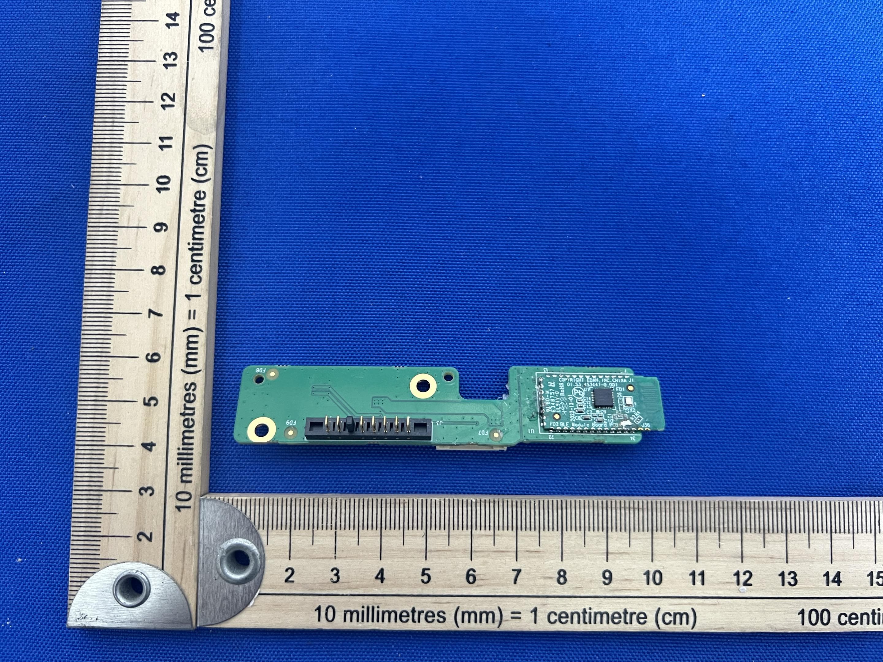
SMQIM3
May 06, 2026Bluetooth module
Equipment Class
DTS - Digital Transmission System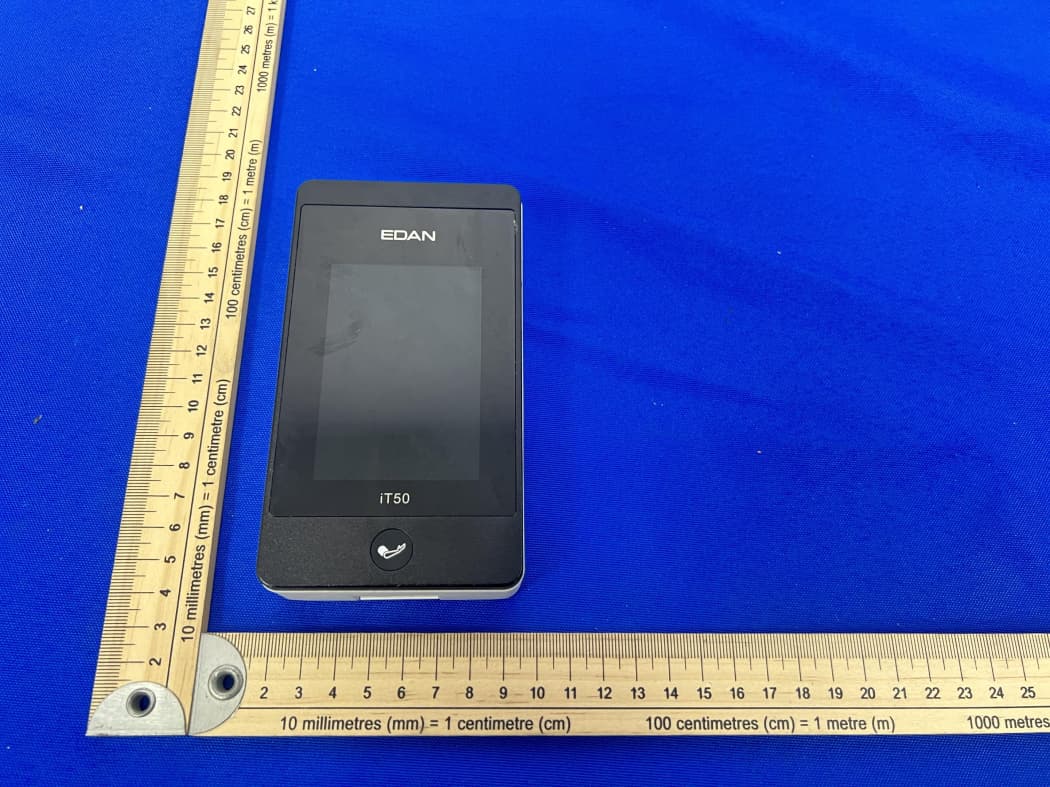
SMQIT50
Jan 30, 2026Telemetry Monitor
Equipment Class
DXX - Part 15 Low Power Communication Device TransmitterSMQIT30
Jan 28, 2026Shenzhen CTL Testing Technology Co., Ltd.
Equipment Class
NII - Unlicensed National Information Infrastructure TX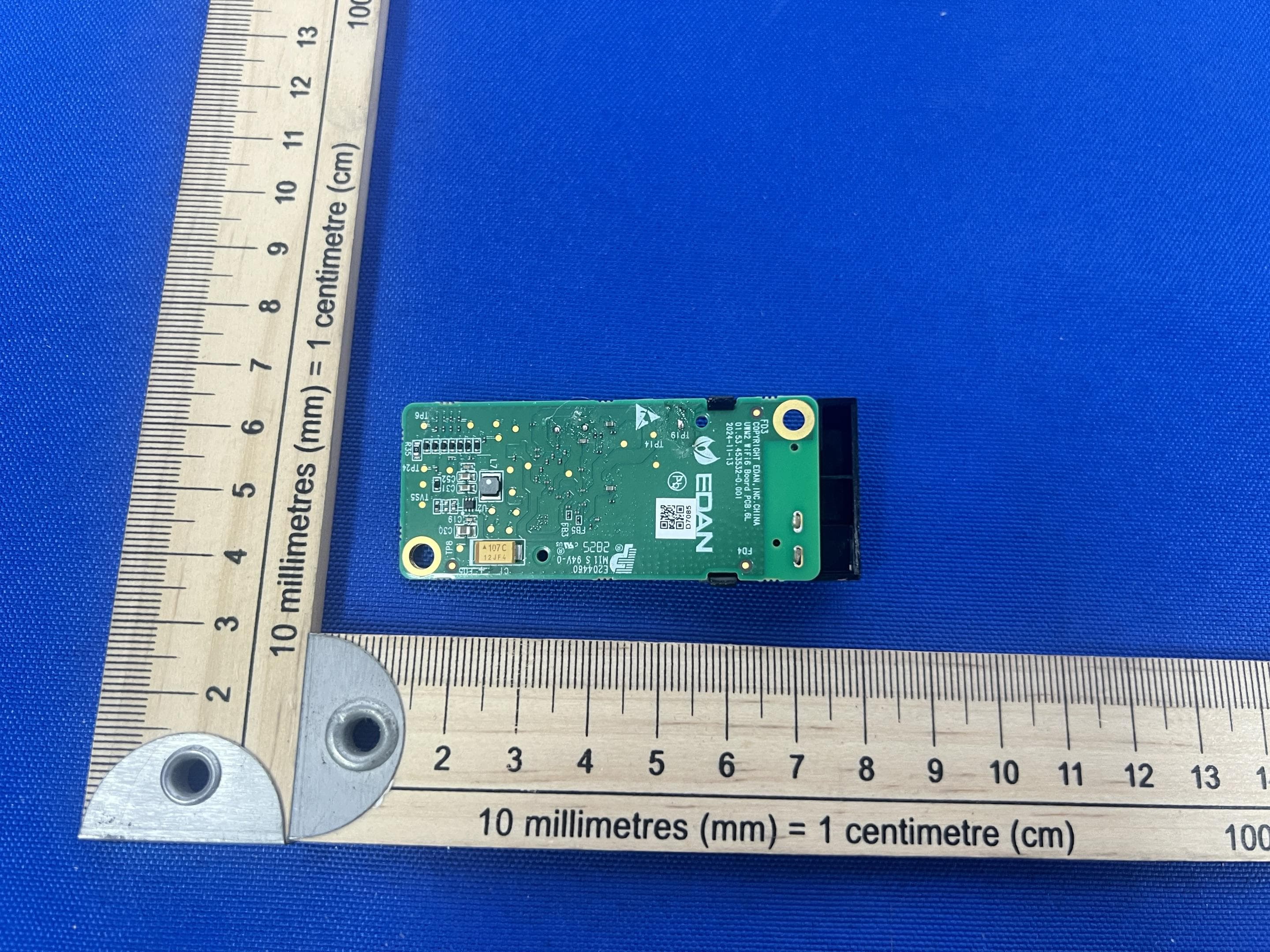
SMQUWM2
Dec 02, 2025WIFI module
Equipment Class
DTS - Digital Transmission System
SMQ-NANOC5
Sep 15, 2024Nano Series Diagnostic Ultrasound Systen
Equipment Class
NII - Unlicensed National Information Infrastructure TX