SMQF15EDANFetal&Maternal Monitor
EDAN INSTRUMENTS, INC.
Click to zoom
Application Details
- Equipment Class
- DXX - Part 15 Low Power Communication Device Transmitter
- Date of Grant
- Apr 11, 2022
- Application Purpose
- Original Equipment
- Date of Application
- Apr 11, 2022
- Equipment Note
- Fetal&Maternal Monitor
- Frequency Range
- 13.56000000 - 13.56000000
- Company
- EDAN INSTRUMENTS, INC.
- Country
- China
Documents & Files
Document Text
Text extracted from the exhibit documents filed with the FCC. Open a document above to read the original.
Users Manual
Traditional 510(k) of Fetal & Maternal Monitor 014_14.1_F15_Series_User_Manual 1202 I About this Manual P/N: 01.54.458308 Version: 1.4 MPN: 01.54.458308014 Release Date: Aug. 2020 © Copyright EDAN INSTRUMENTS, INC. 2019-2020. All rights reserved. Statement This manual will help you understand the operation and maintenance of the product better. It is reminded that the product shall be used strictly complying with this manual. User’s operation failing to comply with this manual may result in malfunction or accident for which EDAN INSTRUMENTS, INC. (hereinafter called EDAN) can not be held liable. EDAN owns the copyrights of this manual. Without prior written consent of EDAN, any materials contained in this manual shall not be photocopied, reproduced or translated into other languages. Materials protected by the copyright law, including but not limited to confidential information such as technical information and patent information are contained in this manual, the user shall not disclose such information to any irrelevant third party. The user shall understand that nothing in this manual grants him, expressly or implicitly, any right or license to use any of the intellectual properties of EDAN. EDAN holds the rights to modify, update, and ultimately explain this manual. Responsibility of the Manufacturer EDAN only considers itself responsible for any effect on safety, reliability and performance of the equipment if: Assembly operations, extensions, re-adjustments, modifications or repairs are carried out by persons authorized by EDAN, and The electrical installation of the relevant room complies with national standards, and The instrument is used in accordance with the instructions for use. Terms Used in this Manual This guide is designed to give key concepts on safety precautions. WARNING A WARNING label advises against certain actions or situations that could result in personal injury or death. CAUTION A CAUTION label advises against actions or situations that could damage equipment, produce inaccurate data, or invalidate a procedure. NOTE A NOTE provides useful information regarding a function or a procedure. Traditional 510(k) of Fetal & Maternal Monitor 014_14.1_F15_Series_User_Manual 2202 II Table of Content Chapter1 Safety Guidance ......................................................................................... 1 1.1 Intended Use/Indications for Use .......................................................................................... 1 1.2 Features ................................................................................................................................ 1 1.3 Instruction for Safe Operation ............................................................................................... 3 1.4 Safety Precautions ................................................................................................................ 3 1.5 Safety Information ................................................................................................................. 2 1.5.1 Protecting Personal Information ................................................................................. 2 1.5.2 Security ....................................................................................................................... 3 1.6 Definitions and Symbols ....................................................................................................... 4 Chapter2 Installation .................................................................................................. 8 2.1 Opening the Package and Checking .................................................................................... 8 2.2 Installing Battery .................................................................................................................... 8 2.2.1 Patient Transfer Within the Hospital ........................................................................... 9 2.3 Installing Monitor ................................................................................................................... 9 2.4 Loading Recorder paper ....................................................................................................... 9 2.5 Connecting Power Cable ..................................................................................................... 11 2.6 Installing Transducer Holder Bracket .................................................................................. 12 Chapter3 Basic Operation ....................................................................................... 14 3.1 Overview ............................................................................................................................. 14 3.1.1 Left Panel .................................................................................................................. 14 3.1.2 Right Panel ............................................................................................................... 15 3.1.3 Rear Panel ................................................................................................................ 16 3.1.4 Bottom Panel ............................................................................................................ 16 3.1.5 Indicators .................................................................................................................. 17 3.2 Transducers and Cables ..................................................................................................... 17 3.2.1 Transducers .............................................................................................................. 18 3.2.2 Remote Event Marker(Optional for F15 Only) .......................................................... 21 3.2.3 DECG Cable ............................................................................................................. 22 3.2.4 DECG-IUP Integrated Cable ................................................…
Text truncated - open the document above for the full version.
Cover Letter(s)
EDAN INSTRUMENTS, INC Agent Authorization Company: EDAN INSTRUMENTS, INC Address: #15 Jinhui Road, Jinsha Community, Kengzi Sub-District, Pingshan District, 518122 Shenzhen P.R.China Product Name: Fetal&Maternal Monitor Model Number(s): F15 Air, F15 Product Description: Fetal&Maternal Monitor We authorize MiCOM Labs Inc., 575 Boulder Court, Pleasanton, California 94566, USA, to act on our behalf on all matters concerning the certification of above named equipment. We declare that MiCOM Labs Inc. is allowed to forward all information related to the approval and certification of equipment to the regulatory agencies as required and to discuss any issues concerning the approval application. Any and all acts carried out by MiCOM Labs on our behalf shall have the same effect as acts of our own. Signature: Date: 2022-01-27 Name: Huanhuan Xia Title: Manager Company: Edan Instruments, Inc
Cover Letter(s)
24January2022 DeclarationOfIdentity ToWhomItMayConcern: WithregardstotheapplicationforModel:F15,Accordingtothedesigner,Edan Instruments,IncweherebydeclarethedifferencebetweenModel:F15andModel:F15air; BasicModelNumber:F15 BasicBrandName:EDAN BasicProductName:Fetal&MaternalMonitor BasicCertificateNumber: ☐New/☒AdditionalModelNumber(s): F15air DeclaretheCircuit,PCBLayout,ElectricalParts,andappearanceofthefollowing product(s)areidenticaltothebasicmodel:F15air Exceptthefollowing(s):Differentmarketingnames. YoursSincerely, EdanInstruments,Inc ChargePersonPrintedName:HuanhuanXia ChargePersonTitle:manager E-Mail:[email protected]
Cover Letter(s)
Date:22January2022 EDANINSTRUMENTS,INC. To:FederalCommunicationsCommission, Authorization&EvaluationDivision, 7435OaklandMillsRoad, Columbia,MD21046 ToWhomItMayConcern: TheEDANINSTRUMENTS,INC.theundersigned,herebyauthorizesMr.WuXuewenfrom ShenzhenBALUNTechnologyCo.,Ltd.,toactonthebehalfoftheEDANINSTRUMENTS,INC. solelyinmattersrelatingtotheapplicationforanFCCequipmentauthorizationforFCCID: SMQF15EDANincludingthesigningofdocumentsinconnectionwiththisApplication. NecessaryactscarriedoutbyShenzhenBALUNTechnologyCo.,Ltd.inconnectionwiththe ApplicationshallhavethesameeffectasactsoftheEDANINSTRUMENTS,INC. TheEDANINSTRUMENTS,INC.alsoherebycertifythatnopartytothisapplicationissubjectto adenialofbenefits,includingFCCbenefits,pursuanttoSection5301oftheAnti-DrugAbuse Actof1988,21U.S.C.Section862. YoursSincerely, HuanhuanXia
Cover Letter(s)
Date:22January2022 EDANINSTRUMENTS,INC. To:FederalCommunicationsCommission, Authorization&EvaluationDivision, 7435OaklandMillsRoad, Columbia,MD21046 Re:EDANINSTRUMENTS,INC. FCCID:SMQF15EDAN FCCCertificationConfidentialityRequest Gentlemen: Thisletteristocomplywith47CFR0.457and0.459pertainingtoconfidentiality material.EDANINSTRUMENTS,INC.requeststhatthefollowingdocuments regardingthissubmissionforFCCID:SMQF15EDANbekeptconfidential: ExhibitTypeFileName BlockDiagramBlockDiagram.pdf SchematicsSchematics.pdf OperationalDescriptionOperationalDescription.pdf Andbelowexhibitkeptshort-termconfidential(180days): ExternalphotosExternalphotos.pdf Testsetupphotostestphoto.pdf InternalphotosInternalphotos.pdf UsermanualUsermanual.pdf Thosedocumentscontaindetailedsystemandequipmentdescriptionandrelated informationabouttheproductwhichEDANINSTRUMENTS,INC.considerstobe confidentialproprietary,acustomdesignand,otherwise,notreleasabletothe generalpublic.Sincethisdesignisabasisformwhichfuturetechnological productswillevolve,EDANINSTRUMENTS,INC.considersthisinformation wouldbeofbenefittoitscompetitors,andthatthedisclosureoftheinformationin thesedocumentswouldgivecompetitorsanunfairadvantageinthemarket. YoursSincerely, HuanhuanXia
External Photos
AnnexNo.:BL-SZ2040038-AW 1 / 4 EUTEXTERNALPHOTOS FRONTVIEWOFEUT REARVIEWOFEUT AnnexNo.:BL-SZ2040038-AW 2 / 4 LEFTSIDEVIEWOFEUT RIGHTSIDEOFEUT AnnexNo.:BL-SZ2040038-AW 3 / 4 TOPVIEWOFEUT CLOSE-UP AnnexNo.:BL-SZ2040038-AW 4 / 4 BOTTOMVIEWOFEUT
ID Label/Location Info
LabelandLabelLocation label: LabelLocation:
Internal Photos
Annex No.: BL-SZ2040038-AI 1 / 14 EUT INTERNAL PHOTOS EUT UNCOVER VIEW MAIN BOARD TOP VIEW PIFA Antenna PIFA Antenna Annex No.: BL-SZ2040038-AI 2 / 14 MAIN BOARD REAR VIEW SECONDARY BOARD 1 TOP VIEW Annex No.: BL-SZ2040038-AI 3 / 14 SECONDARY BOARD 1 REAR VIEW SECONDARY BOARD 2 TOP VIEW Annex No.: BL-SZ2040038-AI 4 / 14 SECONDARY BOARD 2 REAR VIEW SECONDARY BOARD 3 TOP VIEW Annex No.: BL-SZ2040038-AI 5 / 14 SECONDARY BOARD 3 REAR VIEW SECONDARY BOARD 4 REAR VIEW Annex No.: BL-SZ2040038-AI 6 / 14 SECONDARY BOARD 4 REAR VIEW SECONDARY BOARD 5 REAR VIEW Annex No.: BL-SZ2040038-AI 7 / 14 SECONDARY BOARD 5 REAR VIEW SECONDARY BOARD 6 REAR VIEW Annex No.: BL-SZ2040038-AI 8 / 14 SECONDARY BOARD 5 REAR VIEW SECONDARY BOARD 7 REAR VIEW WIFI Chip(MT7628) Annex No.: BL-SZ2040038-AI 9 / 14 SECONDARY BOARD 7 REAR VIEW SECONDARY BOARD 8 REAR VIEW WIFI Chip(RS9113) Annex No.: BL-SZ2040038-AI 10 / 14 SECONDARY BOARD 8 REAR VIEW EUT UNCOVER VIEW NFC Chip QI Chip Annex No.: BL-SZ2040038-AI 11 / 14 EUT UNCOVER VIEW Antenna Annex No.: BL-SZ2040038-AI 12 / 14 NFC Antenna (FRONT) NFC Antenna (REAR) Annex No.: BL-SZ2040038-AI 13 / 14 QI Antenna (FRONT) QI Antenna (REAR) Annex No.: BL-SZ2040038-AI 14 / 14 Battery Photo
RF Exposure Info
RF Exposure Evaluation For FCC ID: SMQF15EDAN Refer user manual this device is a Fetal&Maternal Monitor, and this device was designed used in Mobile devices that the minimum distance between human’s body is 20 cm. Based on the 47CFR 2.1091, this device belongs to Mobile device. The definition of the category as following: Mobile Derives: CFR Title 47 §2.1091(b) (b) For purposes of this section, a mobile device is defined as a transmitting device designed to be used in other than fixed locations and to generally be used in such a way that a separation distance of at least 20 centimeters is normally maintained between the transmitter’s radiating structure(s) and the body of the user or nearby persons. FCC KDB 447498 D01 General RF Exposure Guidance v06 Limit Devices operating in standalone mobile exposure conditions may contain a single transmitter or multiple transmitters that do not transmit simultaneously. A minimum test separation distance ≥ 20 cm is required between the antenna and radiating structures of the device and nearby persons to apply mobile device exposure limits. The distance must be fully supported by the operating and installation configurations of the transmitter and its antenna(s), according to the source-based time-averaged maximum power requirements of § 2.1091(d)(2). In cases where cable losses or other attenuations are applied to determine compliance, the most conservative operating configurations and exposure conditions must be evaluated. The minimum test separation distance required for a device to comply with mobile exposure conditions must be clearly identified in the installation and operating instructions, for all installation and exposure conditions, to enable users and installers to comply with RF exposure requirements. For mobile devices that have the potential to operate in portable device exposure conditions, similar to the configurations described in § 2.1091(d)(4), a KDB inquiry is required to determine the SAR test requirements for demonstrating compliance. When the categorical exclusion provision of § 2.1091(c) applies, the minimum test separation distance may be estimated, when applicable, by simple calculations according to plane-wave equivalent conditions, to ensure the transmitter and its antenna(s) can operate in manners that meet or exceed the estimated distance. The source-based time-averaged maximum radiated power, according to the maximum antenna gain, must be applied to calculate the field strength and power density required to establish the minimum test separation distance. When the estimated test separation distance becomes overly conservative and does not support compliance, MPE measurement or computational modeling may be used to determine the required minimum separation distance. According to FCC Part 1.1307, systems operating under the provisions of this section shall be operated in a manner the ensures that the public is not exposed to radio frequency energy level in excess of the commission’s guidelines. Limits for General Population/ Uncontrolled Exposure Frequency Range (MHz) Electric Field Strength(E)(V/m) Magnetic Field Strength (H)(A/m) Power Density (S)(mW/cm 2 ) 0.3-1.34 614 1.63 (100)* 1.34-30 824/f 2.19/f (180/f2)* 30-300 27.5 0.073 0.2 300-1500 f/1500 1500-100,000 1.0 MPE calculation formula Where: S = power density P = output power (mW) G = power gain of the antenna in the direction of interest relative to an isotropic radiator R = Separation distance between radiator and human body (cm) Test data WIFI Mode Low Channel Middle Channel High Channel Average Power (dBm) 16.24 16.42 16.47 Note: This report listed the worst case Average Power value, please refer to RF test Report No. BL-SZ2040038- 601, section A.1 Output Power. NFC Frequency (MHz) Field Strength @10m (dBuV/m) E-Filed (V/m) 13.557 36.23 0.00006 Note: This report listed the worst case value, please refer to RF test Report No. BL-SZ2040038-402, section A.2 Field Strength of Fundamental Emissions. Turn-up power Mode Range (dBm) WIFI 15.00-17.00 NFC (-70.00)- (-68.00) Test result Mode Maximum Average Power (dBm) Antenna Gain (typical) (dBi): Total Power (mw) Distance (cm) Limit of Power Density (mW/cm²) Power Density (mW/cm²) Power Density/Limit Verdict WIFI 17.00 2 79.43 20 1.00 0.016 0.016 Pass Mode Max. Field Strength (dBuV/m) E-Filed (V/m) Limit of E-Filed (V/m) Power Density/Limit Verdict NFC 36.23 0.00006 60.78 0.001 Pass Collocated Power Density Calculation Note: 1. Σ(Power Density / Limit): This is a summation of [(power density for each transmitter/ antenna included in the simultaneous transmission)/ (corresponding MPE limit)], for WLAN 2.4GHz + NFC. 2. Both of the WLAN and NFC can transmit simultaneously, the formula of calculated the MPE is CPD1 / LPD1 + CPD2 / LPD2 + ......etc. < 1 CPD = Calculation power density LPD = Limit of power density 3. The worst-case situation is 0.017 which is less than “1”. This confirmed that the device comply with FCC 1.1310 MPE limit. 4. The Fetal&Maternal Monitor work frequency range used is 2400 MHz ~ 2483.5 MHz, 13.557 MHz the result close to the limit by the above formula so, we select worst case power to calculate the exclusion power threshold. 5. More power list please refer to RF test report. Conclusion: RF exposure Evaluation Results: Compliance Evolution mode Frequency (MHz) Power Density/Limit Σ(Power Density / Limit) of WIFI + NFC Verdict WIFI 2400 MHz ~ 2483.5 MHz 0.016 0.017 Pass NFC 13.557 MHz 0.001 Pass
Test Report
Block B, 1/F, Baisha Science & Technology Park, Shahe West Road, Nanshan District, Shenzhen, Guangdong Province, China TEL: +86-755-66850100, FAX: +86-755-61824271 Email: [email protected] www.baluntek.com RF ISSUED BY Shenzhen BALUN Technology Co., Ltd. FOR Fetal&Maternal Monitor ISSUED TO Edan Instruments, Inc #15 Jinhui Road, Jinsha Community, Kengzi Sub-District, Pingshan District, 518122 Shenzhen P.R.China Report No.:BL-SZ2040038-402 Tested by: EUT Name:Fetal&Maternal Monitor Xiong Chong Model Name:F15 Air(refer section 2.4) Date Apr. 07, 2022 Brand Name:EDAN Test Standard:47 CFR Part 15 Subpart C (refer section 3.1) Approved by: FCC ID:SMQF15EDAN Liao Jianming (Technical Director) Test Conclusion:Pass Date Apr. 07, 2022 Test Date:Apr. 02, 2020 ~ Mar. 28, 2022 Date of Issue:Apr. 07, 2022 NOTE: This test report of test results only related to testing samples, which can be duplicated completely for the legal use with the approval of the applicant; it shall not be reproduced except in full, without the written approval of Shenzhen BALUN Technology Co., Ltd. Any objections should be raised within thirty days from the date of issue. To validate the report, please contact us. TEST REPORT Report No.: BL-SZ2040038-402 2 / 50 Revision History Version Issue Date Revisions Content Rev. 01 Oct. 27, 2021 Initial Issue Rev. 02 Apr. 07, 2022 Updated all tests Updated Product Type TABLE OF CONTENTS 1 ADMINISTRATIVE DATA (GENERAL INFORMATION) .......................................................................... 4 1.1 Identification of the Testing Laboratory .............................................................................................. 4 1.2 Identification of the Responsible Testing Location ............................................................................. 4 1.3 Laboratory Condition .......................................................................................................................... 4 1.4 Announce ........................................................................................................................................... 4 2 PRODUCT INFORMATION ...................................................................................................................... 5 2.1 Applicant Information ......................................................................................................................... 5 2.2 Manufacturer Information ................................................................................................................... 5 2.3 Factory Information ............................................................................................................................ 5 2.4 General Description for Equipment under Test (EUT) ....................................................................... 5 2.5 Technical Information ......................................................................................................................... 5 3 SUMMARY OF TEST RESULTS .............................................................................................................. 6 3.1 Test Standards ................................................................................................................................... 6 3.2 Verdict ................................................................................................................................................ 6 3.3 Test Uncertainty ................................................................................................................................. 6 4 GENERAL TEST CONFIGURATIONS ..................................................................................................... 7 4.1 Test Environments ............................................................................................................................. 7 4.2 Test Equipment List ........................................................................................................................... 7 4.3 Description of Test Setup ................................................................................................................... 8 4.3.1 For Radiated Test (Below 30 MHz) ............................................................................................. 8 4.3.2 For Radiated Test (30 MHz-1 GHz) ............................................................................................ 8 4.3.3 For AC Power Supply Port Test .................................................................................................. 9 5 TEST ITEMS ........................................................................................................................................... 10 5.1 Antenna Requirements .................................................................................................................... 10 5.1.1 Relevant Standards ................................................................................................................... 10 5.1.2 Antenna Anti-Replacement Construction .................................................................................. 11 Report No.: BL-SZ2040038-402 3 / 50 5.2 Emission Bandwidth ......................................................................................................................... 12 5.2.1 Definition ................................................................................................................................... 12 5.2.2 Test Setup ................................................................................................................................. 12 5.2.3 Test Procedure .......................................................................................................................... 12 5.2.4 Test Result ................................................................................................................................ 13 5.3 Field Strength of Fundamental Emissions and Radiated Emissions .…
Text truncated - open the document above for the full version.
Test Setup Photos
Annex No.: BL-SZ2040038-AE-2 1 / 3 TEST SETUP PHOTOS 1 Radiated Test Photo Below 30MHz 30MHz-1 GHz Annex No.: BL-SZ2040038-AE-2 2 / 3 Close-up 2 Conducted Emissions Test Photo 1 Annex No.: BL-SZ2040038-AE-2 3 / 3 Test Photo 2
Contact Information
Applicant
Huanhuan Xia
Technical Contact
Test Firm
Shenzhen BALUN Technology Co., Ltd.Hanson Lin
[email protected]86-755-66833830
Technical Specifications
| # | Rule Parts | Frequency Range | Power Output |
|---|---|---|---|
| 1 | 15C | 13.56 MHz - 13.56 MHz | - |
Other Applications from EDAN INSTRUMENTS, INC.
SMQIM3
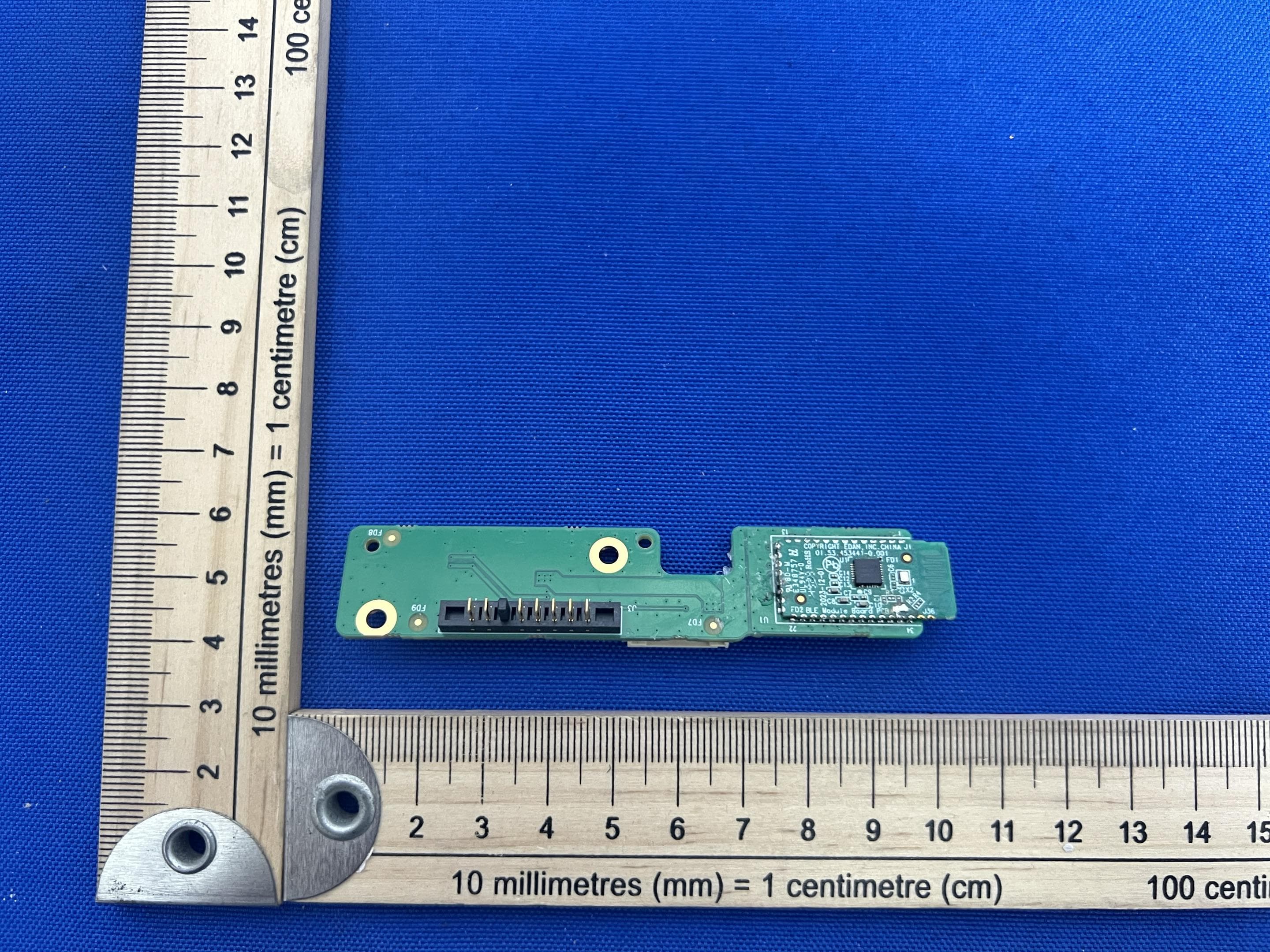
May 06, 2026Bluetooth module
Equipment Class
DTS - Digital Transmission System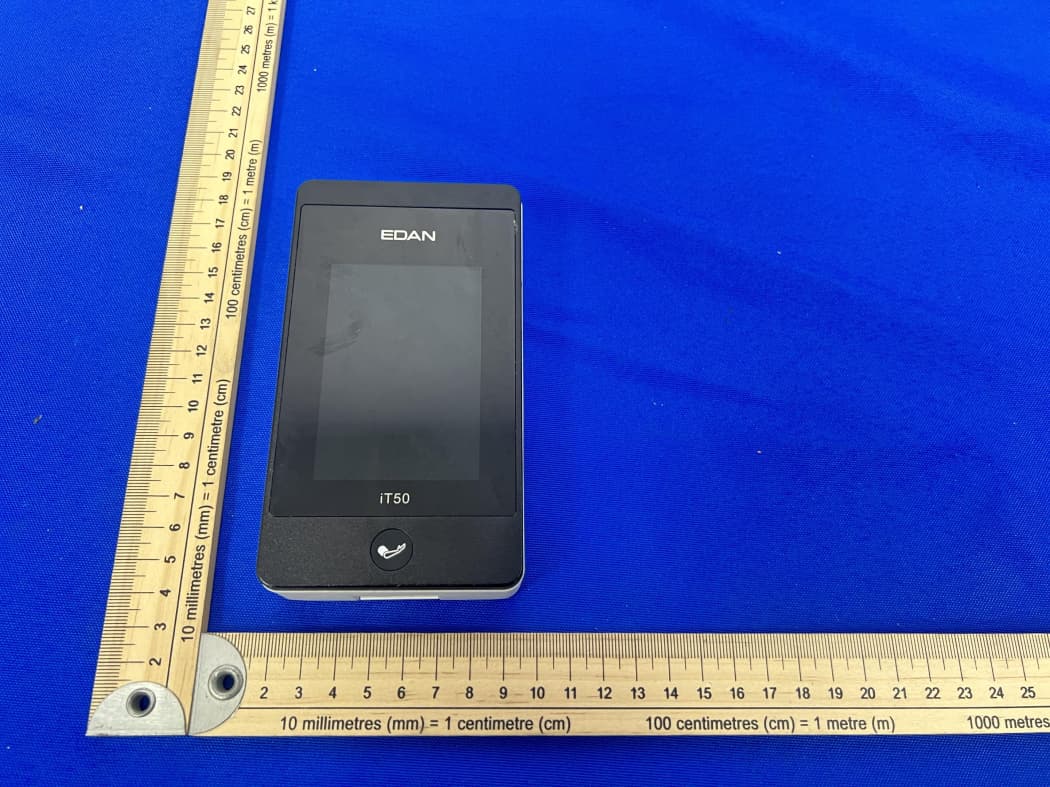
SMQIT50
Jan 30, 2026Telemetry Monitor
Equipment Class
DXX - Part 15 Low Power Communication Device TransmitterSMQIT30
Jan 28, 2026Shenzhen CTL Testing Technology Co., Ltd.
Equipment Class
NII - Unlicensed National Information Infrastructure TX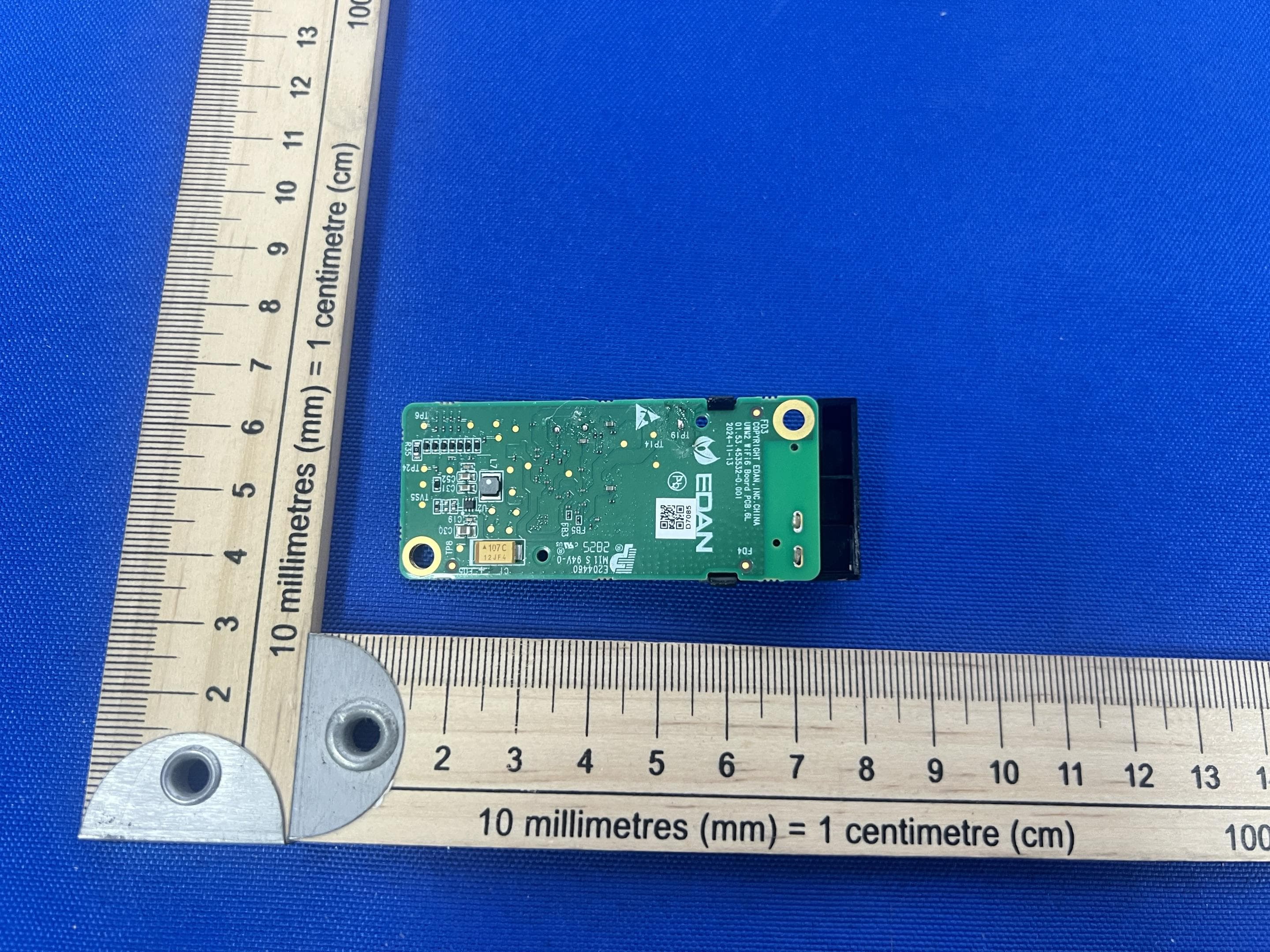
SMQUWM2
Dec 02, 2025WIFI module
Equipment Class
DTS - Digital Transmission System
SMQ-NANOC5
Sep 15, 2024Nano Series Diagnostic Ultrasound Systen
Equipment Class
NII - Unlicensed National Information Infrastructure TX