SMQIM70EDANPatient Monitor
EDAN INSTRUMENTS, INC.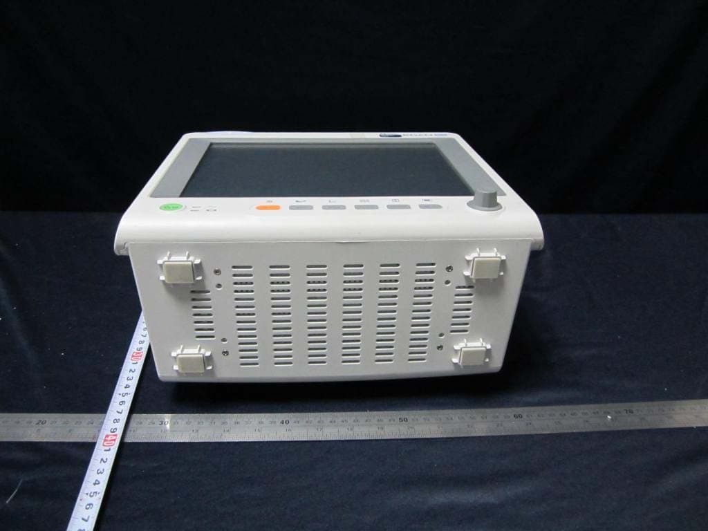
Click to zoom
Application Details
- Equipment Class
- DTS - Digital Transmission System
- Date of Grant
- Nov 05, 2013
- Application Purpose
- Original Equipment
- Date of Application
- Nov 05, 2013
- Equipment Note
- Patient Monitor
- Frequency Range
- 2412.00000000 - 2462.00000000
- Company
- EDAN INSTRUMENTS, INC.
- Country
- China
Documents & Files
Document Text
Text extracted from the exhibit documents filed with the FCC. Open a document above to read the original.
Users Manual
I About this Manual P/N: 01.54.455711-1201 Release Date: August 2013 © Copyright EDAN INSTRUMENTS, INC. 2012-2013. All rights reserved. Statement This manual will help you understand the operation and maintenance of the product better. It is reminded that the product shall be used strictly complying with this manual. User’s operation failing to comply with this manual may result in malfunction or accident for which EDAN INSTRUMENTS, INC. (hereinafter called EDAN) cannot be held liable. EDAN owns the copyrights of this manual. Without prior written consent of EDAN, any materials contained in this manual shall not be photocopied, reproduced or translated into other languages. Materials protected by the copyright law, including but not limited to confidential information such as technical information and patent information are contained in this manual, the user shall not disclose such information to any irrelevant third party. The user shall understand that nothing in this manual grants him, expressly or implicitly, any right or license to use any of the intellectual properties of EDAN. EDAN holds the rights to modify, update, and ultimately explain this manual. Responsibility of the Manufacturer EDAN only considers itself responsible for any effect on safety, reliability and performance of the equipment if: Assembly operations, extensions, re-adjustments, modifications or repairs are carried out by persons authorized by EDAN, and The electrical installation of the relevant room complies with national standards, and The instrument is used in accordance with the instructions for use. Upon request, EDAN may provide, with compensation, necessary circuit diagrams, and other information to help qualified technician to maintain and repair some parts, which EDAN may define as user serviceable. II Terms Used in this Manual This guide is designed to give key concepts on safety precautions. WARNING A WARNING label advises against certain actions or situations that could result in personal injury or death. CAUTION A CAUTION label advises against actions or situations that could damage equipment, produce inaccurate data, or invalidate a procedure. NOTE A NOTE provides useful information regarding a function or a procedure. III Table of Contents Chapter 1 Intended Use and Safety Guidance ................................................................................1 1.1 Intended Use...........................................................................................................................1 1.2 Safety Guidance .....................................................................................................................2 1.3 Explanation of Symbols on the Monitor ................................................................................4 Chapter 2 Installation ........................................................................................................................8 2.1 Initial Inspection.....................................................................................................................8 2.2 Mounting the Monitor ............................................................................................................8 2.2.1 Installing Wall Mount for the Monitor ........................................................................8 2.3 Connecting the Power Cable ..................................................................................................8 2.4 Checking Out the Monitor .....................................................................................................8 2.5 Checking the Recorder ...........................................................................................................9 2.6 Setting the Date and Time ......................................................................................................9 2.7 Handing Over the Monitor .....................................................................................................9 2.8 FCC Statement* .....................................................................................................................9 2.9 FCC RF Radiation Exposure Statement*.............................................................................10 Chapter 3 Basic Operation .............................................................................................................. 11 3.1 Overview .............................................................................................................................. 11 3.1.1 Front View................................................................................................................. 11 3.1.2 Rear View ..................................................................................................................14 3.1.3 Side View ..................................................................................................................18 3.1.4 Configuration ............................................................................................................20 3.2 Operating and Navigating ....................................................................................................20 3.2.1 Using Keys ................................................................................................................22 3.3 Operating Mode ...................................................................................................................23 3.3.1 Demo Mode...............................................................................................................23 3.3.2 Standby Mode ...........................................................................................................24 3.3.3 Night Mode ...............................................................................................................24 3.4 Changing Monitor Settings ..................................................................................................24 3.4.1 …
Text truncated - open the document above for the full version.
Users Manual
Patient Monitor User Manual Basic Operation - 14 - 8 Start / Stop Recording — Press this button to start a real-time recording. During the recording, press this button again to stop recording. 9 Menu — Press this button to return to the main interface when there is no menu open. 10 Rotary Knob (hereinafter called knob) — The user can rotate the knob clockwise or anticlockwise. This operation can make the highlighted item shift up, down, left or right to choose the desired item. Remember, when using the knob, rotate this button to highlight, and press it to select the item. 3.1.2 Rear View iM50 1 Equipotential grounding terminal, if the monitor or other processing unit are used in internal examinations on the heart, ensure that the room incorporates an equipotential grounding system to which the monitor and other processing unit have separate connection. 2 Fan 3 Anti-theft lock interface 4 Security lock, used to prevent the power supply cord from falling. 5 Power Supply Inlet 6 USB interface, this port is used to connect the USB device. 1 2 3 4 5 6 7 8 9 10 11 Patient Monitor User Manual Basic Operation - 15 - 7 VGA Interface 8 Network interface, this port is used to connect to the central monitoring system through the standard network wire. 9 Defibrillator synchronization / analog output. When the user selects Analog Output, the monitor outputs the waveform through the auxiliary output port. When the user selects Defibrillation the monitor outputs the defibrillator synchronization signal through the auxiliary output port. 10 Speaker 11 SD Card iM60/iM70 1 SD Card 2 USB interface, this port is used to connect the USB device. 3 Network interface, this port is used to connect to the central monitoring system through the standard network wire. 4 VGA output 1 2 3 4 5 8 9 10 11 6 7 Patient Monitor User Manual Basic Operation - 16 - 5 Defibrillator synchronization/ analog output/ nurse call port: When the user selects Analog Output, the monitor outputs the waveform through the auxiliary output port. When the user selects Defibrillation, the monitor outputs the defibrillator synchronization signal through the auxiliary output port. When the port is used as nurse call port, it is connected to the call system. When there is an alarm, the monitor outputs nurse call signal to notify the nurse. 6 Anti-theft lock interface 7 Heat sink 8 Speaker 9 Equipotential grounding terminal, if the monitor or other processing unit are used in internal examinations on the heart, ensure that the room incorporates an equipotential grounding system to which the monitor and other processing unit have separate connection. 10 Power Supply Inlet 11 Security lock, used to prevent the power supply cord from falling. iM80 1 2 3 4 5 6 7 8 9 10 11 12 13 Patient Monitor User Manual Basic Operation - 17 - 1 SD Card 2 Nurse call port, this port is connected to the call system. When there is an alarm, the monitor outputs nurse call signal to notify the nurse. 3 Defibrillator synchronization / analog output. When the user selects Analog Output, the monitor outputs the waveform through the auxiliary output port. When the user selects Defibrillation, the monitor outputs the defibrillator synchronization signal through the auxiliary output port. 4 VGA output 5 USB interface, this port is used to connect the USB device. 6 RS232 interface 7 Network interface, this port is used to connect to the central monitoring system through the standard network wire. 8 Anti-theft lock interface 9 Heat emission hole 10 Security lock, used to prevent the power supply cord from falling. 11 Equipotential grounding terminal, if the monitor or other processing unit are used in internal examinations on the heart, ensure that the room incorporates an equipotential grounding system to which the monitor and other processing unit have separate connection. 12 Speaker 13 Fan Patient Monitor User Manual Basic Operation - 18 - 3.1.3 Side View iM50 1 Sensor interface 2 CO 2 module holder 3 Recorder door 4 Battery door iM60/iM70 1 2 3 4 1 2 3 4 Patient Monitor User Manual Basic Operation - 19 - 1 Sensor port 2 CO 2 module holder 3 Recorder door 4 Battery door iM80 1 Sensor port 2 AG module holder 3 Recorder door 4 Battery door 1 2 3 4 Patient Monitor User Manual Basic Operation - 20 - 3.1.4 Configuration Model Size (L×W×H) Function Configuration iM50 261 mm (L) × 198 mm (W) × 215 mm (H) ECG, RESP, SpO 2 , NIBP, IBP ,TEMP, Quick TEMP, CO 2 iM60 303mm(L) × 161mm(W) × 254mm(H) ECG, RESP, SpO 2 , NIBP, TEMP, IBP, C.O., CO 2 iM70 328mm(L) × 158mm(W) × 285mm(H) ECG, RESP, SpO 2 , NIBP, TEMP, IBP, C.O., CO 2 , AG iM80 370 mm (L) × 175 mm (W) × 320 mm (H) ECG, RESP, SpO 2 , NIBP, TEMP, IBP, C.O., CO 2 , AG 3.2 Operating and Navigating Everything you need to operate the monitor is contained on its screen. Almost every element on the screen is interactive. Screen elements include measurement data, waveforms, screen keys, information fields, alarms fields and menus. The configurability of the monitor means that often you can access the same element in different ways. For example, you might be able to access an item through its on-screen setup menu, via a hard key, or via a shortcut key. The User Manual always describes how to access items via an on-screen menu. You may use whichever way you find most convenient. Patient Monitor User Manual Basic Operation - 21 - 1 Department 2 Bed number 3 Patient name 4 Patient type 5 Alarm status area 6 Alarm off 7 Measurement value 8 Menu 9 Date and time 10 Scroll right to display more shortcut keys 11 Networking symbol 12 Battery status symbol 13 AC power supply symbol Patient Monitor User Manual Basic Operation - 22 - 14 Shortcut key area 15 Scroll left to display more shortcut keys 16 Mute key 17 Parameter waveform 3.2.1 Using Keys The monitor has four different types of keys: 3.2.1.1 Permanent Keys A permanent key is a graphical key that remains on the screen all the time to give you fast access to functions. Menu – enter the main setu…
Text truncated - open the document above for the full version.
Cover Letter(s)
Edan Instruments, Inc. FCC ID: SMQIM70EDAN DATE: Aug 20, 2013 We , Edan Instruments, Inc. doesn’t provide any controls or software to allow the operation outside of the USA frequency band when we sell this product in USA.
External Photos
External photos of the EUT
ID Label/Location Info
Patient Monitor Model: iM70 Edan Instruments, Inc. 3/F - B,Nanshan Medical Equipments Park,Nanhai Rd 1019#, Shekou,Nanshan Shenzhen,518067 P.R. China Tel:+86-755-26898326 Fax:+86-755-26898330 YYYY-MM Anti-electro-shock Type:ClassI 100V-240V~ 50Hz/60Hz 1.4A-0.7A Shanghai International Holding Corp.GmbH(Europe) Eiffestrasse 80,D-20537 Hamburg Germany Tel:+49-40-2513175 Fax:+49-40-255726 CCCC Rx only (U.S.) http:// www.edan.com.cn IPX1 FCC ID:SMQIM70EDAN Label and Label Loaction FCC ID : SMQIM70EDAN This device complies with Part 15 of the FCC Rules. Operation is subject to the following two conditions: (1) this device may not cause harmful interference, and (2) this device must accept any interference received, including interference that may cause undesired operation. Label Loaction
Internal Photos
Internal photos of the EUT
RF Exposure Info
MPE TEST REPORT FCC Per 47 CFR 2.1091(b) Report Reference No. ..................... : FCC ID. ............................................ : TRE1303011202 R/C: 76529 SMQIM70EDAN Compiled by ( position+printed name+signature) .. : File administrators Jerome Luo Supervised by ( position+printed name+signature) .. : Test Engineer Yuchao Wang Approved by ( position+printed name+signature) .. : Manager Wenliang Li Date of issue ..................................... : Aug 05, 2013 Testing Laboratory Name .............. : Shenzhen Huatongwei International Inspection Co., Ltd Address ............................................. : Keji Nan No.12 Road, Hi-tech Park, Shenzhen, China Applicant’s name ............................ : Edan Instruments, Inc. Address ............................................. : 3/F - B, Nanshan Medical Equipments Park, Nanhai Rd 1019#, Shekou, Nanshan Shenzhen,518067 P.R. China Test specification: Standard ........................................... : FCC Per 47 CFR 2.1091(b) KDB447498 v05r01 TRF Originator .................................. : Shenzhen Huatongwei International Inspection CO., Ltd Master TRF ....................................... : Dated 2006-06 Shenzhen Huatongwei International Inspection Co., Ltd. All rights reserved. This publication may be reproduced in whole or in part for non-commercial purposes as long as the Shenzhen Huatongwei International Inspection Co., Ltd is acknowledged as copyright owner and source of the material. Shenzhen Huatongwei International Inspection Co., Ltd takes no responsibility for and will not assume liability for damages resulting from the reader's interpretation of the reproduced material due to its placement and context. Test item description .................... : Patient Monitor Trade Mark ....................................... : Manufacturer .................................... : Edan Instruments, Inc. Model/Type reference ....................... : iM70 Listed Models .................................. : / Ratings .............................................. : AC 120V/60Hz Modulation ....................................... : CCK,OFDM Operation Frequency ........................ : From 2412MHz to 2462MHz Result ................................................ : Positive Report No.: TRE1303011202 Page 2 of 7 Issued:2013-08-05 MPE T E S T R E P O R T Test Report No. : TRE1303011202 Aug 05, 2013 ______________________________________________________________________________________________ Date of issue Equipment under Test : Patient Monitor Model /Type : iM70 Listed Models : / Applicant : Edan Instruments, Inc. Address : 3/F - B, Nanshan Medical Equipments Park, Nanhai Rd 1019#, Shekou, Nanshan Shenzhen,518067 P.R. China Manufacturer Edan Instruments, Inc. Address : 3/F - B, Nanshan Medical Equipments Park, Nanhai Rd 1019#, Shekou, Nanshan Shenzhen,518067 P.R. China The test report merely corresponds to the test sample. It is not permitted to copy extracts of these test result without the written permission of the test laboratory. Report No.: TRE1303011202 Page 3 of 7 Issued:2013-08-05 Contents 1. SUMMARY 4 1.1. EUT configuration 4 1.2. NOTE 4 2. TEST ENVIRONMENT 5 2.1. Address of the test laboratory 5 2.2. Environmental conditions 5 2.3. Statement of the measurement uncertainty 5 3. METHOD OF MEASUREMENT 5 3.1. Applicable Standard 5 3.2. Limit 6 3.3. MPE Calculation Method 6 4. CONCLUSION 7 Report No.: TRE1303011202 Page 4 of 7 Issued:2013-08-05 1. SUMMARY 1.1. EUT configuration The following peripheral devices and interface cables were connected during the measurement: ● - supplied by the manufacturer ○ - supplied by the lab ● Power Cable Length (m) : 1.20 Shield : Unshielded Detachable : Undetachable : ○ Multimeter Manufacturer : / Model No. : / 1.2. NOTE 1. The EUT is an 802.11b/g/n Patient Monitor ,The functions of the EUT listed as below: Test Standards Reference Report WLAN 802.11b/g/n FCC Part 15 Subpart C TRE1303012001 MPE FCC Per 47 CFR 2.1091(d) TRE1303012002 2. The frequency bands used in this EUT are listed as follows: Frequency Band(MHz) 2400-2483.5 5150-5350 5470-5725 5725-5850 802.11b √ - - - 802.11g √ - - - 802.11n(20MHz) √ - - - 802.11n(40MHz) - - - - 3. The EUT incorporates a SISO function,Physically,the EUT provides one completed transmitter and one completed receiver. Modulation Mode TX Function 802.11b 1TX 802.11g 1TX 802.11n (20MHz) 1TX 802.11n (40MHz) - . Report No.: TRE1303011202 Page 5 of 7 Issued:2013-08-05 2. TEST ENVIRONMENT 2.1. Address of the test laboratory Shenzhen Huatongwei International Inspection Co., Ltd Keji Nan No.12 Road, Hi-tech Park, Shenzhen, China Phone: 86-755-26715686 Fax: 86-755-26748089 The sites are constructed in conformance with the requirements of ANSI C63.7, ANSI C63.4 (2009) and CISPR Publication 22. 2.2. Environmental conditions During the measurement the environmental conditions were within the listed ranges: Temperature: 15-35 ° C Humidity: 30-60 % Atmospheric pressure: 950-1050mbar 2.3. Statement of the measurement uncertainty The data and results referenced in this document are true and accurate. The reader is cautioned that there may be errors within the calibration limits of the equipment and facilities. The measurement uncertainty was calculated for all measurements listed in this test report acc. to TR-100028-01” Electromagnetic compatibility and Radio spectrum Matters (ERM);Uncertainties in the measurement of mobile radio equipment characteristics; Part 1” and TR-100028-02 “Electromagnetic compatibility and Radio spectrum Matters (ERM);Uncertainties in the measurement of mobile radio equipment characteristics; Part 2 “ and is documented in the Shenzhen Huatongwei International Inspection Co., Ltd quality system acc. to DIN EN ISO/IEC 17025. Furthermore, component and process variability of devices similar to that tested may result in additional deviation. The manufacturer has the sole responsibility of continued compliance of the device. Hereafter the b…
Text truncated - open the document above for the full version.
Test Report
FCC PART 15 SUBPART C TEST REPORT FCC PART 15.247 Report Reference No. ..................... : FCC ID. .............................................: TRE1303011201 R/C: 76529 SMQIM70EDAN Compiled by ( position+printed name+signature) .. : File administrators Jerome Luo Supervised by ( position+printed name+signature) .. : Test Engineer Yuchao Wang Approved by ( position+printed name+signature) .. : Manager Wenliang Li Date of issue ..................................... : Aug 05, 2013 Testing Laboratory Name .............. : Shenzhen Huatongwei International Inspection Co., Ltd Address ............................................ : Keji Nan No.12 Road, Hi-tech Park, Shenzhen, China Applicant’s name ............................ : Edan Instruments, Inc. Address ............................................ : 3/F - B, Nanshan Medical Equipments Park, Nanhai Rd 1019#, Shekou, Nanshan Shenzhen,518067 P.R. China Test specification: Standard ........................................... : FCC Part 15.247: Operation within the bands 902-928 MHz, 2400-2483.5 MHz and 5725-5850 MHz TRF Originator .................................. : Shenzhen Huatongwei International Inspection CO., Ltd Master TRF ....................................... : Dated 2006-06 Shenzhen Huatongwei International Inspection Co., Ltd. All rights reserved. This publication may be reproduced in whole or in part for non-commercial purposes as long as the Shenzhen Huatongwei International Inspection Co., Ltd is acknowledged as copyright owner and source of the material. Shenzhen Huatongwei International Inspection Co., Ltd takes no responsibility for and will not assume liability for damages resulting from the reader's interpretation of the reproduced material due to its placement and context. Test item description ..................... : Patient Monitor Trade Mark ....................................... : Model/Type reference ....................... : iM70 Listed Models .................................. : / Manufacturer .................................. : Edan Instruments, Inc. Modulation Type ............................... : CCK,OFDM Operation Frequency ........................ : From 2412MHz to 2462MHz Rating ............................................... : AC 120V/60Hz Result................................................ : Positive Report No.: TRE1303011201 Page 2 of 77 Issued:2013-08-05 T E S T R E P O R T Test Report No. : TRE1303011201 Aug 05, 2013 ______________________________________________________________________________________________ Date of issue Equipment under Test : Patient Monitor Model /Type : iM70 Listed Models : / Applicant : Edan Instruments, Inc. Address : 3/F - B, Nanshan Medical Equipments Park, Nanhai Rd 1019#, Shekou, Nanshan Shenzhen,518067 P.R. China Manufacturer Edan Instruments, Inc. Address : 3/F - B, Nanshan Medical Equipments Park, Nanhai Rd 1019#, Shekou, Nanshan Shenzhen,518067 P.R. China Test Result according to the standards on page 4: Positive The test report merely corresponds to the test sample. It is not permitted to copy extracts of these test result without the written permission of the test laboratory. Report No.: TRE1303011201 Page 3 of 77 Issued:2013-08-05 Contents 1. TEST STANDARDS .................................................................. 4 2. SUMMARY ............................................................................. 5 2.1. General Remarks 5 2.2. Equipment Under Test 5 2.3. Description of the test mode 5 2.4. Short description of the Equipment under Test (EUT) 5 2.5. EUT operation mode 5 2.6. EUT configuration 5 2.7. Related Submittal(s) / Grant (s) 6 2.8. Modifications 6 2.9. NOTE 6 3. TEST ENVIRONMENT ............................................................... 7 3.1. Address of the test laboratory 7 3.2. Test Facility 7 3.3. Environmental conditions 8 3.4. Configuration of Tested System 8 3.5. Test Description 8 3.6. Statement of the measurement uncertainty 8 3.7. Equipments Used during the Test 9 4. TEST CONDITIONS AND RESULTS ............................................ 10 4.1. AC Power Conducted Emission 10 4.2. Radiated Emission 13 4.3. Maximum Peak Output Power 22 4.4. Power Spectral Density 29 4.5. Band Edge Compliance of RF Emission 36 4.6. Spurious RF Conducted Emission 45 4.7. 6dB Bandwidth 55 4.8. Antenna Requirement 62 5. TEST SETUP PHOTOS OF THE EUT .......................................... 63 6. EXTERNAL AND INTERNAL PHOTOS OF THE EUT ....................... 65 Report No.: TRE1303011201 Page 4 of 77 Issued:2013-08-05 1. TEST STANDARDS The tests were performed according to following standards: FCC Rules Part 15.247: Frequency Hopping, Direct Spread Spectrum and Hybrid Systems that are in operation within the bands of 902-928 MHz, 2400-2483.5 MHz, and 5725-5850 MHz. ANSI C63.10:2009 : American National Standard for Testing Unlicensed Wireless Devices KDB558074 D01 V03: Guidance for Performing Compliance Measurements on Digital Transmission Systems (DTS) Operating Under §15.247 Report No.: TRE1303011201 Page 5 of 77 Issued:2013-08-05 2. SUMMARY 2.1. General Remarks Date of receipt of test sample : Jun 15, 2013 Testing commenced on : Jul 25, 2013 Testing concluded on : Aug 05, 2013 2.2. Equipment Under Test Power supply system utilised Power supply voltage : ● 120V / 60 Hz ○ 115V / 60Hz ○ 12 V DC ○ 24 V DC ○ Other (specified in blank below) 2.3. Description of the test mode IEEE 802.11b/g/n: Eleven channels are provided to the EUT. Channel Frequency(MHz) Channel Frequency(MHz) 1 2412 8 2447 2 2417 9 2452 3 2422 10 2457 4 2427 11 2462 5 2432 12 2467 6 2437 13 2472 7 2442 2.4. Short description of the Equipment under Test (EUT) The EUT (Patient Monitor (M/N:iM70)) equiped with a 2.4G wifi module. For more details, refer to the user’s manual of the EUT. Serial number: Prototype 2.5. EUT operation mode The EUT has been tested under typical operating condition. The Applicant provides command to control the EUT for staying in continous transmitting an…
Text truncated - open the document above for the full version.
Test Setup Photos
Test Setup Photos of the EUT
Contact Information
Applicant
Huanhuan Xia
Test Firm
Shenzhen Huatongwei International Insp. Co., LtdMoffy Yu
Technical Specifications
| # | Rule Parts | Frequency Range | Power Output |
|---|---|---|---|
| 1 | 15C | 2.41 GHz - 2.46 GHz | 45.00 mW |
Other Applications from EDAN INSTRUMENTS, INC.
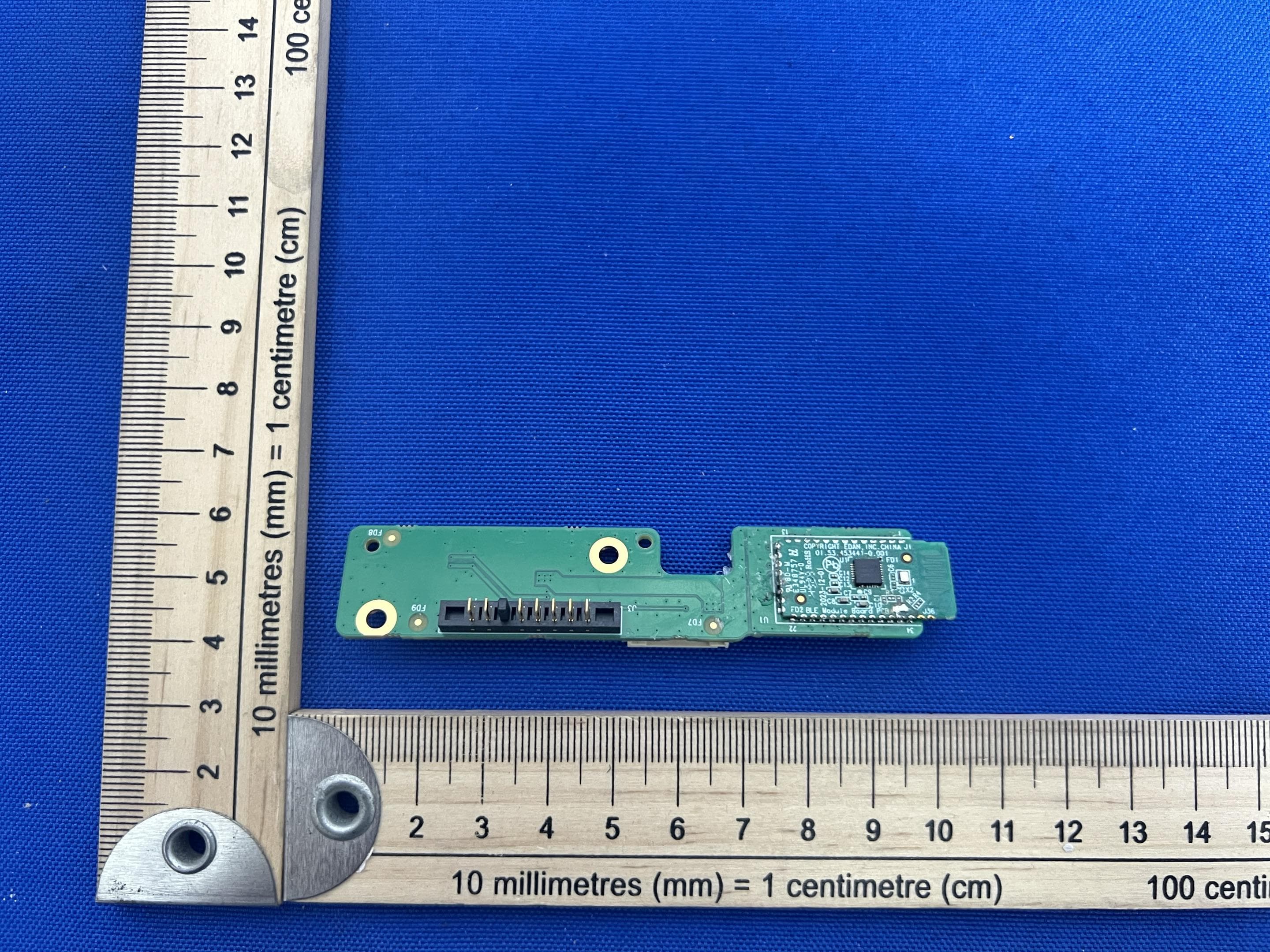
SMQIM3
May 06, 2026Bluetooth module
Equipment Class
DTS - Digital Transmission System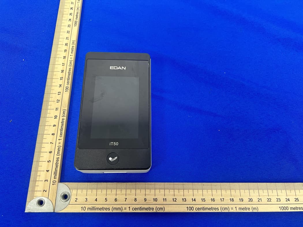
SMQIT50
Jan 30, 2026Telemetry Monitor
Equipment Class
DXX - Part 15 Low Power Communication Device TransmitterSMQIT30
Jan 28, 2026Shenzhen CTL Testing Technology Co., Ltd.
Equipment Class
NII - Unlicensed National Information Infrastructure TX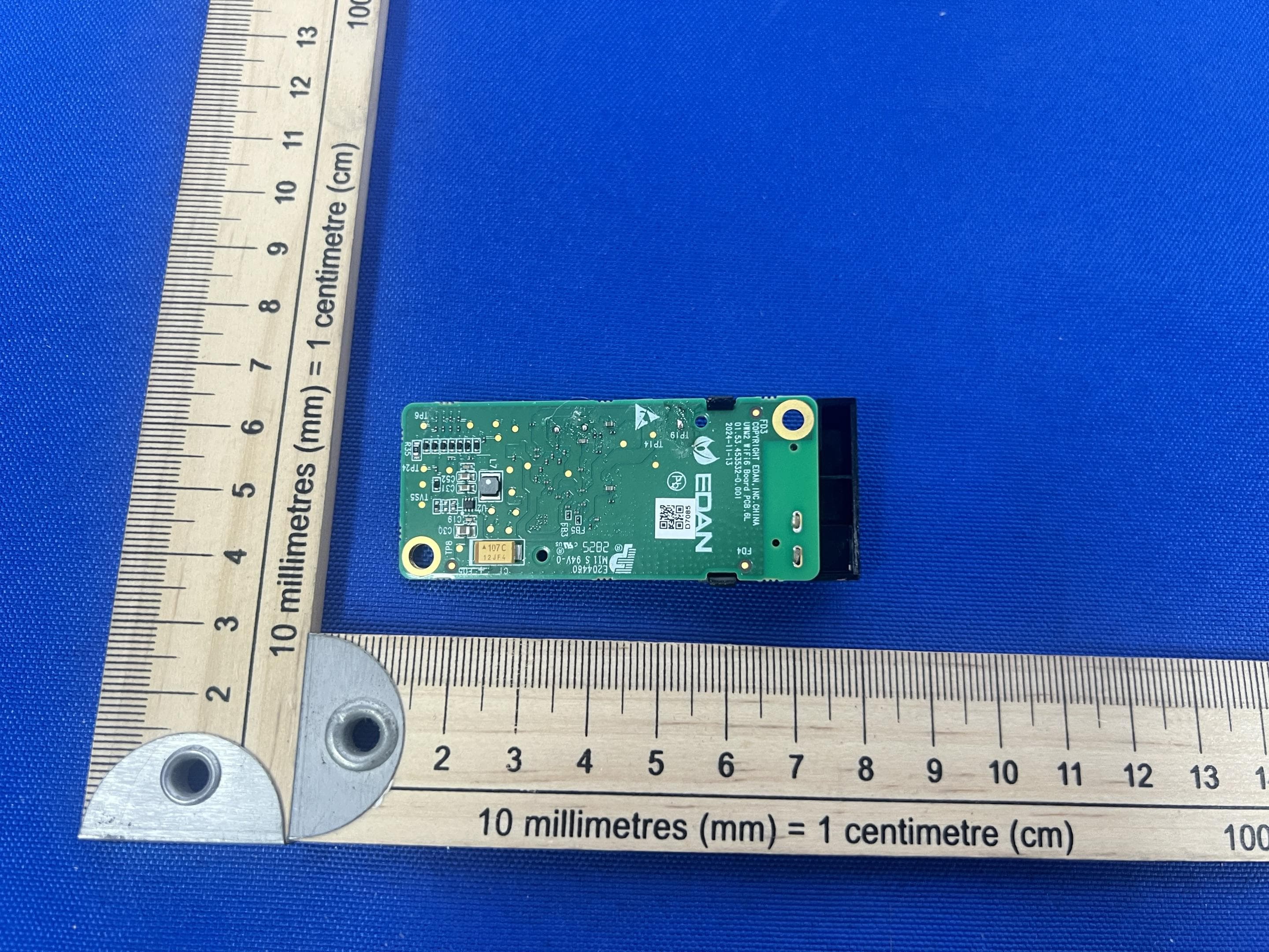
SMQUWM2
Dec 02, 2025WIFI module
Equipment Class
DTS - Digital Transmission System
SMQ-NANOC5
Sep 15, 2024Nano Series Diagnostic Ultrasound Systen
Equipment Class
NII - Unlicensed National Information Infrastructure TX