SMQV1102EDANSMQV1102EDAN WIFI Module
EDAN INSTRUMENTS, INC.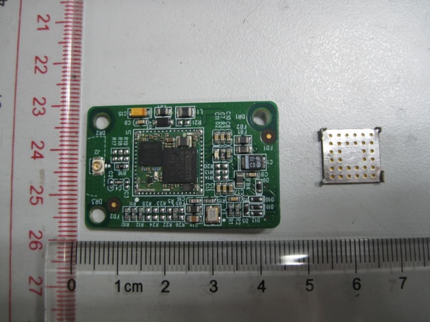
Click to zoom
Application Details
- Equipment Class
- DTS - Digital Transmission System
- Date of Grant
- Apr 22, 2015
- Application Purpose
- Original Equipment
- Date of Application
- Apr 21, 2015
- Equipment Note
- SMQV1102EDAN WIFI Module
- Frequency Range
- 2412.00000000 - 2462.00000000
- Company
- EDAN INSTRUMENTS, INC.
- Country
- China
Documents & Files
Document Text
Text extracted from the exhibit documents filed with the FCC. Open a document above to read the original.
Users Manual
Redpine Signals, Inc. Proprietary and Confidential R S 9110-N-11-02 802.11bgn WLAN Module Data Sheet V V e e r r s s i i o o n n 1 1 . . 4 4 8 8 Se p tember 2011 Redpine Signals, Inc. 2107 N. First Street, #680 Sa n Jose, CA 95131. Tel: (408) 748-3385 Fax: (408) 705-2019 Email: [email protected] We bsite: www.redpinesignals.com Red pine Signals, Inc. Proprietary and confidential Page 2 RS9110-N-11-02 802.11bgn WLAN Module Data Sheet Version 1.48 Overview T h e RS9110-N-11-02 module is a complete IEEE 802.11bgn Wi-Fi client device with an integrated MAC, Baseband processor, and RF transceiver with power amplifier. Based on the Redpine Signals RS9110-LI MAC/BBP chip, the module provides a complete end-to-end solution for low-power WLAN applications. It includes a multi- threaded processor and a rich set of peripheral interfaces. It can connect to a host processor through SDIO and SPI interfaces. Applications: • VOIP handsets • Interactive remote control devices • Industrial automation and telemetry • MP3 music and MP4 video players • Digital cameras and camcorders Device Features: • Conforms to IEEE 802.11b/g/e/i standards, single-stream 802.11 n • 802.11n MAC features for high user throughput • 802.11n Space Time Block Code (STBC) support for extended range and higher throughput • Host interface through SDIO and SPI • Bluetooth coexistence • Integrated multi-threaded processor • TCP checksum offloading • Rich set of peripherals – UART, SPI, I2C, GPIO, and timers • 2.4 GHz, 802.11n RF transceiver with high performance power amplifier • Complete WLAN software along with host driver for various operating systems such as Windows XP, Linux, Windows CE • Single supply 3.1 to 3.6 V operation RS9110-N-11-02 System Block Diagram RS9110-N-11-02 RF Transce iv er + PA Balun EEPROM T/R Switch Host Interface 3.3V Peripheral I/O Frequency Reference RS9110-LI Red pine Signals, Inc. Proprietary and confidential Page 3 RS9110-N-11-02 802.11bgn WLAN Module Data Sheet Version 1.48 T a ble of Contents 1 : Detailed Feature List ............................................................ 7 1.1: Host Interfaces...................................................................... 7 1.2: WLAN.................................................................................... 7 1.2.1: MAC.............................................................................................. 7 1.2.2: Baseband Processing.................................................................... 7 1.2.3: RF Transceiver.............................................................................. 7 1.3: Multi-Threaded Processor ...................................................... 7 1.4: Peripherals............................................................................ 8 1.5: Coexistence........................................................................... 8 1.6: Software ............................................................................... 8 1.7: Compliance and Certification.................................................. 8 2: Package Description............................................................. 9 2.1: Top View ............................................................................... 9 2.2: Bottom View.......................................................................... 9 2.3: Package Dimensions............................................................ 10 2.4: Recommended Reflow Profile............................................... 11 2.5: Baking Instructions ............................................................. 11 3: Pin Description................................................................... 12 3.1: Module Pinout...................................................................... 12 3.2: Pin Description .................................................................... 12 4: Electrical Characteristics.................................................... 19 4.1: Absolute Maximum Ratings.................................................. 19 4.2: Recommended Operating Conditions.................................... 19 4.3: DC Characteristics – Digital I/O Signals ............................... 19 4.4: AC Characteristics – Digital I/O Signals................................ 20 4.4.1: SDIO Interface ........................................................................... 20 4.4.1.1: Full Speed Mode.................................................................... 20 4.4.1.2: High Speed Mode .................................................................. 21 4.4.2: SPI Interface.............................................................................. 21 4.4.2.1: Full Speed Mode.................................................................... 22 4.4.2.2: High Speed Mode .................................................................. 22 4.4.3: Reset Timing............................................................................... 23 4.4.4: JTAG Interface............................................................................ 24 5: Module Power Consumption............................................... 25 6: Performance Specifications................................................ 26 6.1: Wireless Specifications ........................................................ 26 6.2: Receive Characteristics........................................................ 26 6.2.1: Sensitivity................................................................................... 26 6.3: Standards Compliance ......................................................... 26 7: Software Details................................................................. 28 7.1: Architecture ........................................................................ 28 7.2: Details................................................................................. 28 7.2.1: 802.1x Supplicant....................................................................... 29 7.2.2: Configuration Utility…
Text truncated - open the document above for the full version.
Cover Letter(s)
EDAN INSTRUMENTS,INC. Request for Confidentiality Date: 2015-04-10 Subject: Confidentiality Request for: SMQV1102EDAN Pursuant to FCC 47 CRF 0.457(d) and 0.459 and IC RSP-100, Section 10, the applicant requests that a part of the subject FCC application be held confidential. Type of Confidentiality Requested Exhibit Short Term Permanent Block Diagrams Short Term External Photos Short Term Permanent* 1 Internal Photos Short Term Permanent Operation Description/Theory of Operation Short Term Permanent Parts List & Placement/BOM Short Term Permanent Tune-Up Procedure Short Term PermanentSchematics Short Term Test Setup Photos Short Term Permanent* User’s Manual *Note: ______(Insert Explanation as Necessary)______ EDAN INSTRUMENTS,INC. has spent substantial effort in developing this product and it is one of the first of its kind in industry. Having the subject information easily available to "competition" would negate the advantage they have achieved by developing this product. Not protecting the details of the design will result in financial hardship. Permanent Confidentiality: The applicant requests the exhibits listed above as permanently confidential be permanently withheld from public review due to materials that contain trade secrets and proprietary information not customarily released to the public. Short-Term Confidentiality: The applicant requests the exhibits selected above as short term confidential be withheld from public view for a period of ___(specify number of days not to exceed 180 ) 2 ___ days from the date of the Grant of Equipment Authorization and prior to marketing. This is to avoid premature release of sensitive information prior to marketing or release of the product to the public. Applicant is also aware that they are responsible to notify ACB in the event information regarding the product or the product is made available to the public. ACB will then release the documents listed above for public disclosure pursuant to FCC Public Notice DA 04-1705. NOTE for Industry Canada Applications: The applicant understands that until such time that IC distinguishes between Short Term and Permanent Confidentiality, either type of marked exhibit above will simply be marked Confidential when submitted to IC. Sincerely, By: (Signature3) (Print name): Xia Huanhuan 1 - The asterisked items (*) require further justification before permanent confidentiality will be allowed. These also currently require review by the FCC under their Permit-But-Ask policy before the grant is issued and can delay completion of an application. Further justification should be added to the note above. One such example for a potted device would be: “The EUT is FULLY potted using a non-removable epoxy based material. Removal of potting material causes irreparable damage to internal circuitry. See photographs exhibits that outline the device before and after potting.” 2 - Please refer to http://acbcert.com/documents/misc-docs/Memo-Short-Term-Vs-Standard-Confidentiality.pdf for complete details. 3 - Must be signed by applicant contact given for applicant on the FCC site, or by the authorized agent if an appropriate authorized agent letter has been provided. Letters should be placed on appropriate letterhead.
Cover Letter(s)
EDAN INSTRUMENTS,INC. To the FCC or FCC TCB handling this application Hereby we, Company name (grantee) EDAN INSTRUMENTS,INC. Addresss 3/F-B,Nanshan Medical Equipment Park,Nanhai Rd 1019#,Shekou,Nanshan City / ZIP / State / Country Shenzhen,518067 P.R. CHINA request modular approval for the certification of our equipment within this application, identified by: FCC ID: SMQV1102EDAN The table below contains the justification for modular approval of this equipment: Requirement 15.212 Explanation from grantee (do not write yes / no, but explain why it complies / how it is achieved) 1. The modular transmitter must have its own RF shielding. Use ironclad to shielding RF part, Physical components and tuning capacitor(s) are located external to the shield, and on the module assembly 2. The modular transmitter must have buffered modulation/data inputs (if such inputs are provided) to ensure that the module will comply with Part 15 requirements under conditions of excessive data rates or over-modulation. The RF module comply with Part 15 requirements under conditions of excessive data rates or over- modulation 3. The modular transmitter must have its own power supply regulation. The WIFI module U1 has its own FCC ID:XF6- RS9110N1102 already apply as single module .So the new module add Peripheral Circuit also has its own voltage control circuits 4. The modular transmitter must comply with the antenna requirements of Section 15.203 and 15.204(c). The antenna must either be permanently attached or employ a “unique” antenna coupler (at all connections between the module and the antenna, including the cable).. Use Integral Antenna. 5. The modular transmitter must be tested in a stand-alone configuration, i.e., the module must not be inside another device during testing. This is intended to demonstrate that the module is capable of complying with Part 15 emission limits regardless of the device into which it is eventually installed. The modular transmitter tested in a stand-alone configuration, isn’t inside another device during testing 6. The modular transmitter must be labeled with its own FCC ID number, and, if the FCC ID is not visible when the module is installed inside another device, then the outside of the device into which the module is installed must also display a label referring to the enclosed module. This exterior label can use wording such as the following: “Contains Transmitter Module FCC ID: XYZMODEL1” or “Contains FCC ID: XYZMODEL1.” Any similar wording that expresses the same meaning may be used. The Grantee may either provide such a label, an example of which must be included in the application for equipment authorization, or, must provide adequate instructions along with the module which explain this requirement. In the latter case, a copy of these instructions must be included in the application for equipment authorization. Have own FCCID: SMQV1102EDAN, If the FCC ID is not visible when the module is installed inside another device, the OEM integrator shall apply a label in a visible area on his product with the following statement: Contains Transmitter Module FCC ID: SMQV1102EDAN 7. The modular transmitter must comply with any specific rule or operating requirements applicable to the transmitter and the manufacturer must provide adequate instructions along with the module to explain any such requirements. A copy of these instructions must be included in the application for equipment authorization. For example, there are very strict operational and timing requirements that must be met before a transmitter is authorized for operation under Section 15.231. For instance, data transmission is prohibited, except for operation under Section 15.231(e), in which case there are separate field strength level and timing requirements. Compliance with these requirements must be assured. YES 8. The modular transmitter must comply with any applicable RF exposure requirements. For example, FCC Rules in Sections 2.1091, 2.1093 and specific Sections of Part 15, including 15.319(i), 15.407(f), 15.253(f) and 15.255(g), require that Unlicensed PCS, UNII and millimeter wave devices perform routine environmental evaluation for RF Exposure to demonstrate compliance. In addition, spread spectrum transmitters operating under Section 15.247 are required to address RF Exposure compliance in accordance with Section 15.247(b)(4). Modular transmitters approved under other Sections of Part 15, when necessary, may also need to address certain RF Exposure concerns, typically by providing specific installation and operating instructions for users, installers and other interested parties to ensure compliance. Any Changes or modifications not expressly approved by the party responsible for compliance could void the user's authority to operate the equipment. The device is compliant with all applicable RF exposure requirements Attestation (by grantee) City and Country: Date: Name: (this must be a person) Function: Signature: (or official company stamp) Shenzhen,China Apr 24,2015 Xia Huanhuan
External Photos
Report No: TRE1412004501 Page: 41 of 42 6. External and Internal Photos of the EUT Report No: TRE1412004501 Page: 42 of 42 .........End of Report.......
ID Label/Location Info
12.0 11.0 P/N:RS9110-N-11-02 FCC ID:SMQV1102EDAN
Internal Photos
Report No: TRE1412004501 Page: 41 of 42 6. External and Internal Photos of the EUT Report No: TRE1412004501 Page: 42 of 42 .........End of Report.......
RF Exposure Info
MPE TEST REPORT FCC Per 47 CFR 2.1091(b) Report Reference No. ..................... : FCC ID. ............................................ : TRE1412004502 R/C: 14449 SMQV1102EDAN Compiled by ( position+printed name+signature) .. : File administrators Yingchun Shan Supervised by ( position+printed name+signature) .. : Project Engineer Yingchun Shan Approved by ( position+printed name+signature) .. : RF Manager Hans Hu Date of issue ..................................... : Mar 24, 2015 Testing Laboratory Name .............. : Shenzhen Huatongwei International Inspection Co., Ltd Address ............................................. : Keji Nan No.12 Road, Hi-tech Park, Shenzhen, China Applicant’s name ............................ : EDAN INSTRUMENTS,INC. Address ............................................. : 3/F-B,Nanshan Medical Equipment Park,Nanhai Rd 1019#,Shekou,Nanshan Shenzhen,518067 P.R. CHINA Test specification: Standard ........................................... : FCC Per 47 CFR 2.1091(b) KDB447498 v05r01 TRF Originator .................................. : Shenzhen Huatongwei International Inspection CO., Ltd Master TRF ....................................... : Dated 2006-06 Shenzhen Huatongwei International Inspection Co., Ltd. All rights reserved. This publication may be reproduced in whole or in part for non-commercial purposes as long as the Shenzhen Huatongwei International Inspection Co., Ltd is acknowledged as copyright owner and source of the material. Shenzhen Huatongwei International Inspection Co., Ltd takes no responsibility for and will not assume liability for damages resulting from the reader's interpretation of the reproduced material due to its placement and context. Test item description .................... : SMQV1102EDAN WIFI Module Trade Mark ....................................... : Manufacturer .................................... : EDAN INSTRUMENTS,INC. Model/Type reference ....................... : V1102EDAN Listed Models .................................. : / Ratings .............................................. : DC3.3V Modulation ....................................... : CCK,OFDM Operation Frequency ........................ : From 2412MHz to 2462MHz Result ................................................ : Positive Report No.:TRE1412004502 Page 2 of 7 Issued:2015-03-24 MPE T E S T R E P O R T Test Report No. : TRE1412004502 Mar 24, 2015 ______________________________________________________________________________________________ Date of issue Equipment under Test : SMQV1102EDAN WIFI Module Model /Type : V1102EDAN Listed Models : / Applicant : EDAN INSTRUMENTS,INC. Address : 3/F - B, Nanshan Medical Equipments Park, Nanhai Rd 1019#, Shekou, Nanshan Shenzhen,518067 P.R. China Manufacturer EDAN INSTRUMENTS,INC. Address : 3/F - B, Nanshan Medical Equipments Park, Nanhai Rd 1019#, Shekou, Nanshan Shenzhen,518067 P.R. China The test report merely corresponds to the test sample. It is not permitted to copy extracts of these test result without the written permission of the test laboratory. Report No.:TRE1412004502 Page 3 of 7 Issued:2015-03-24 Contents 1. SUMMARY 4 1.1. EUT configuration 4 1.2. NOTE 4 2. TEST ENVIRONMENT 5 2.1. Address of the test laboratory 5 2.2. Environmental conditions 5 2.3. Statement of the measurement uncertainty 5 3. METHOD OF MEASUREMENT 5 3.1. Applicable Standard 5 3.2. Limit 6 3.3. MPE Calculation Method 6 4. CONCLUSION 7 Report No.:TRE1412004502 Page 4 of 7 Issued:2015-03-24 1. SUMMARY 1.1. EUT configuration The following peripheral devices and interface cables were connected during the measurement: ● - supplied by the manufacturer ○ - supplied by the lab ● Power Cable Length (m) : 1.20 Shield : Unshielded Detachable : Undetachable : ○ Multimeter Manufacturer : / Model No. : / 1.2. NOTE 1. The EUT is an 802.11b/g/n Patient Monitor ,The functions of the EUT listed as below: Test Standards Reference Report WLAN 802.11b/g/n FCC Part 15 Subpart C TRE1412004501 MPE FCC Per 47 CFR 2.1091(d) TRE1412004502 2. The frequency bands used in this EUT are listed as follows: Frequency Band(MHz) 2400-2483.5 5150-5350 5470-5725 5725-5850 802.11b √ - - - 802.11g √ - - - 802.11n(20MHz) √ - - - 802.11n(40MHz) - - - - 3. The EUT incorporates a SISO function,Physically,the EUT provides one completed transmitter and one completed receiver. Modulation Mode TX Function 802.11b 1TX 802.11g 1TX 802.11n (20MHz) 1TX 802.11n (40MHz) - . Report No.:TRE1412004502 Page 5 of 7 Issued:2015-03-24 2. TEST ENVIRONMENT 2.1. Address of the test laboratory Shenzhen Huatongwei International Inspection Co., Ltd Keji Nan No.12 Road, Hi-tech Park, Shenzhen, China Phone: 86-755-26715686 Fax: 86-755-26748089 The sites are constructed in conformance with the requirements of ANSI C63.7, ANSI C63.4 (2009) and CISPR Publication 22. 2.2. Environmental conditions During the measurement the environmental conditions were within the listed ranges: Temperature: 15-35 ° C Humidity: 30-60 % Atmospheric pressure: 950-1050mbar 2.3. Statement of the measurement uncertainty The data and results referenced in this document are true and accurate. The reader is cautioned that there may be errors within the calibration limits of the equipment and facilities. The measurement uncertainty was calculated for all measurements listed in this test report acc. to TR-100028-01” Electromagnetic compatibility and Radio spectrum Matters (ERM);Uncertainties in the measurement of mobile radio equipment characteristics; Part 1” and TR-100028-02 “Electromagnetic compatibility and Radio spectrum Matters (ERM);Uncertainties in the measurement of mobile radio equipment characteristics; Part 2 “ and is documented in the Shenzhen Huatongwei International Inspection Co., Ltd quality system acc. to DIN EN ISO/IEC 17025. Furthermore, component and process variability of devices similar to that tested may result in additional deviation. The manufacturer has the sole responsibility of continued compliance of the device. …
Text truncated - open the document above for the full version.
Test Report
The test report merely corresponds to the test sample. It is not permitted to copy extracts of these test result without the written permission of the test laboratory. TEST REPORT Report Reference No. .................... : TRE1412004501 R/C..........:14449 FCC ID ............................................. : SMQV1102EDAN Applicant’s name ........................... : EDAN INSTRUMENTS,INC. Address ............................................. : 3/F-B,Nanshan Medical Equipment Park,Nanhai Rd 1019#,Shekou,Nanshan Shenzhen,518067 P.R. CHINA Manufacturer......................................: EDAN INSTRUMENTS,INC. Address...............................................: 3/F-B,Nanshan Medical Equipment Park,Nanhai Rd 1019#,Shekou,Nanshan Shenzhen,518067 P.R. CHINA Test item description .................... : SMQV1102EDAN WIFI Module Trade Mark ....................................... : Model/Type reference ....................... : V1102EDAN Listed Model(s) ................................. : / Standard ......................................... : FCC CFR Title 47 Part 15 Subpart C Section 15.247 Date of receipt of test sample...........: Dec 09, 2014 Date of testing..............................: Dec 10, 2014- Mar 24, 2015 Date of issue.................................: Mar 24, 2015 Result .................. ........................: PASS Compiled by ( position+printedname+signature) ... : File administrators Yingchun Shan Supervised by ( position+printed name+signature) .. : Project Engineer Yingchun Shan Approved by ( position+printed name+signature) .. : RF Manager Hans Hu Testing Laboratory Name ............. : Shenzhen Huatongwei International Inspection Co., Ltd Address ............................................. : Bldg3, Hongfa Hi-tech Industrial Park, Genyu Road, Shenzhen, China Shenzhen Huatongwei International Inspection Co., Ltd. All rights reserved. This publication may be reproduced in whole or in part for non-commercial purposes as long as the Shenzhen Huatongwei International Inspection Co., Ltd is acknowledged as copyright owner and source of the material. Shenzhen Huatongwei International Inspection Co., Ltd takes no responsibility for and will not assume liability for damages resulting from the reader's interpretation of the reproduced material due to its placement and context. Report No: TRE1412004501 Page: 2 of 42 Contents 1. APPLICABLE STANDARDS AND TEST DESCRIPTION 3 1.1. Applicable Standards 3 1.2. Test Description 3 2. SUMMARY 4 2.1. Client Information 4 2.2. Product Description 4 2.3. Operation state 5 2.4. EUT configuration 5 2.5. Modifications 5 3. TEST ENVIRONMENT 6 3.1. Address of the test laboratory 6 3.2. Test Facility 6 3.3. Equipments Used during the Test 7 3.4. Environmental conditions 8 3.5. Statement of the measurement uncertainty 8 4. TEST CONDITIONS AND RESULTS 9 4.1. Antenna requirement 9 4.2. Conducted Emission (AC Main) 10 4.3. Conducted Peak Output Power 13 4.4. Power Spectral Density 14 4.5. 6dB bandwidth 17 4.6. Restricted band (Conducted) 20 4.7. Band edge and Spurious Emission (conducted) 24 4.8. Spurious Emission (radiated) 34 5. TEST SETUP PHOTOS OF THE EUT 4 0 6. EXTERNAL AND INTERNAL PHOTOS OF THE EUT 4 1 Report No: TRE1412004501 Page: 3 of 42 1. APPLICABLE STANDARDS AND TEST DESCRIPTION 1.1. Applicable Standards The tests were performed according to following standards: FCC Rules Part 15.247: Frequency Hopping, Direct Spread Spectrum and Hybrid Systems that are in operation within the bands of 902-928 MHz, 2400-2483.5 MHz, and 5725-5850 MHz. ANSI C63.10-2009 :AmericanNationalStandardforTestingUnlicensedWirelessDevices KDB558074 D01 V03R02: Guidance for Performing Compliance Measurements on Digital Transmission Systems (DTS) 1.2. Test Description Report Section Test Item FCC Rule Result 4.1 Antenna requirement 15.203/15.247 (c) Pass 4.2 Line Conducted Emission (AC Main) 15.207 Pass 4.3 Conducted Peak Output Power 15.247 (b)(3) Pass 4.4 Power Spectral Density 15.247 (e) Pass 4.5 6dB Bandwidth 15.247 (a)(2) Pass 4.6 Restricted band 15.247(d)/15.205 Pass 4.7/4.8 Spurious Emission 15.247(d)/15.209 Pass Remark: The measurement uncertainty is not included in the test result. Report No: TRE1412004501 Page: 4 of 42 2. SUMMARY 2.1. Client Information Applicant: EDAN INSTRUMENTS,INC. Address: 3/F-B,Nanshan Medical Equipment Park,Nanhai Rd 1019#,Shekou,Nanshan Shenzhen,518067 P.R. CHINA Manufacturer: EDAN INSTRUMENTS,INC. Address: 3/F-B,Nanshan Medical Equipment Park,Nanhai Rd 1019#,Shekou,Nanshan Shenzhen,518067 P.R. CHINA 2.2. Product Description Name of EUT Patient Monitor Trade Mark: Model No.: V1102EDAN Listed Model(s): / Power supply: DC3.3V Adapter information: / WIFI Supported type: 802.11b/802.11g/802.11n(H20) Modulation: 802.11b: DSSS (DBPSK / DQPSK / CCK) 802.11g/n(H20): OFDM (BPSK / QPSK / 16QAM / 64QAM) Operation frequency: 802.11b/g/n(H20): 2412MHz~2462MHz Channel number: 802.11b/g/n(H20): 11 Channel separation: 5MHz Antenna type: Internal Antenna Antenna gain: 2.0dBi Report No: TRE1412004501 Page: 5 of 42 2.3. Operation state Test frequency list According to section 15.31(m), regards to the operating frequency range over 10 MHz, must select three channel which were tested. the Lowest frequency, the middle frequency, and the highest frequency of channel were selected to perform the test, please see the above gray bottom. 802.11b/g/n(H20) Channel Frequency (MHz) 01 2412 02 2417 03 2422 ... ... 06 2437 ...... 09 2452 10 2457 11 2462 Data Rated Preliminary tests were performed in different data rate, and found which the below bit rate is worst case mode, so only show data which it is a worst case mode. Mode data rate (worst mode) 802.11b 1Mbps 802.11g 6Mbps 802.11n(H20) 6.5Mbps (MCS0) Test mode For RF test items: the engineering test program was provided and enabled to make EUT continuous transmit/receive. For AC power line conducted emissions: the EUT was set to connect with the WLAN AP under large package sizes transmission. 2.4. EUT…
Text truncated - open the document above for the full version.
Test Setup Photos
Report No: TRE1412004501 Page: 40 of 42 5. Test Setup Photos of the EUT Radiated Emission Conducted Emission (AC Mains)
Contact Information
Applicant
Huanhuan Xia
Technical Contact
EDAN INSTRUMENTS, INC.Huanhuan Xia
[email protected]86-755-26682547
3/F-B, Nanshan Medical Equipment Park · Shenzhen · China
Test Firm
Shenzhen Huatongwei International Insp. Co., LtdMoffy Yu
Technical Specifications
| # | Rule Parts | Frequency Range | Power Output |
|---|---|---|---|
| 1 | 15C | 2.41 GHz - 2.46 GHz | 40.90 mW |
Other Applications from EDAN INSTRUMENTS, INC.
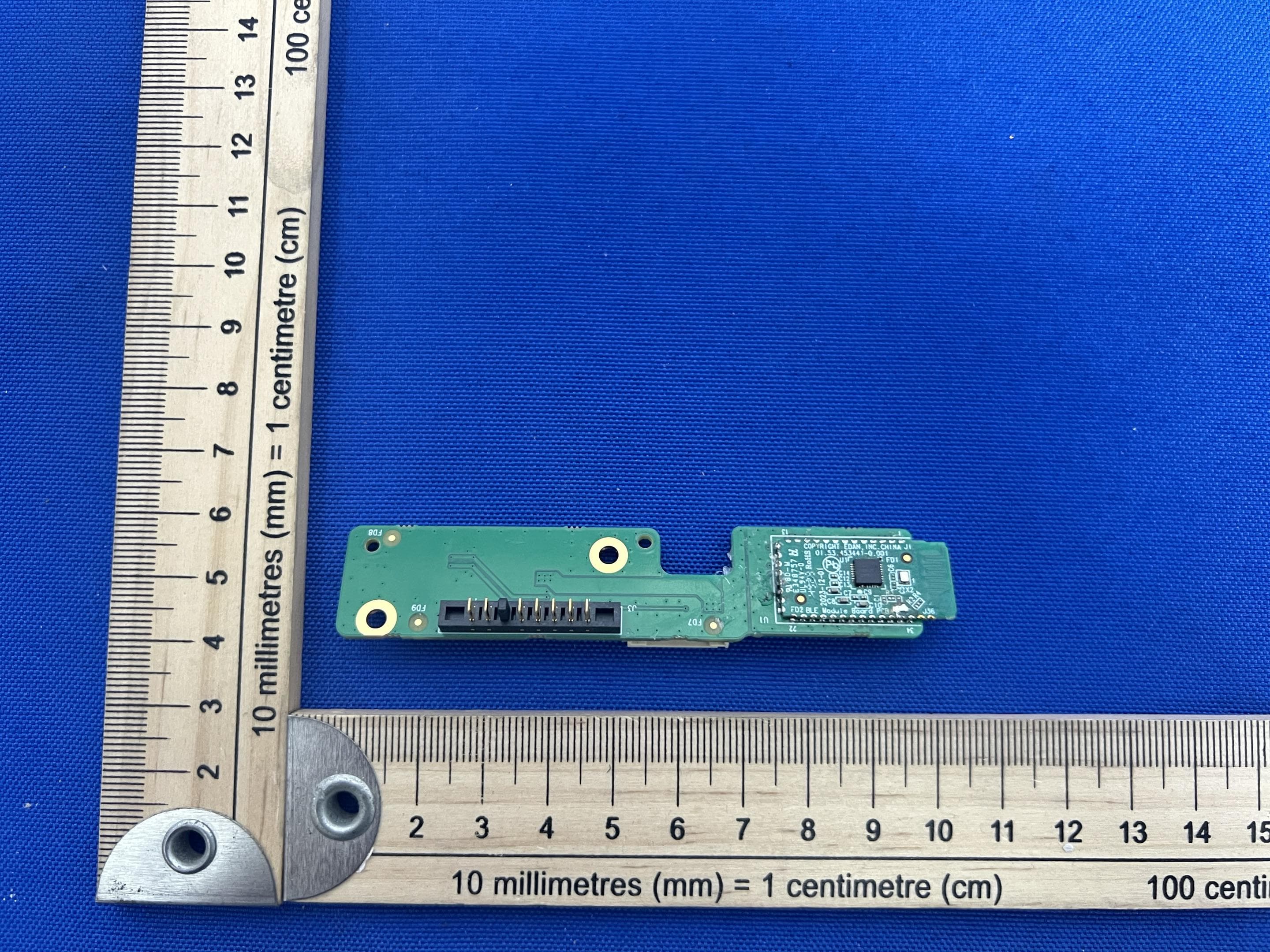
SMQIM3
May 06, 2026Bluetooth module
Equipment Class
DTS - Digital Transmission System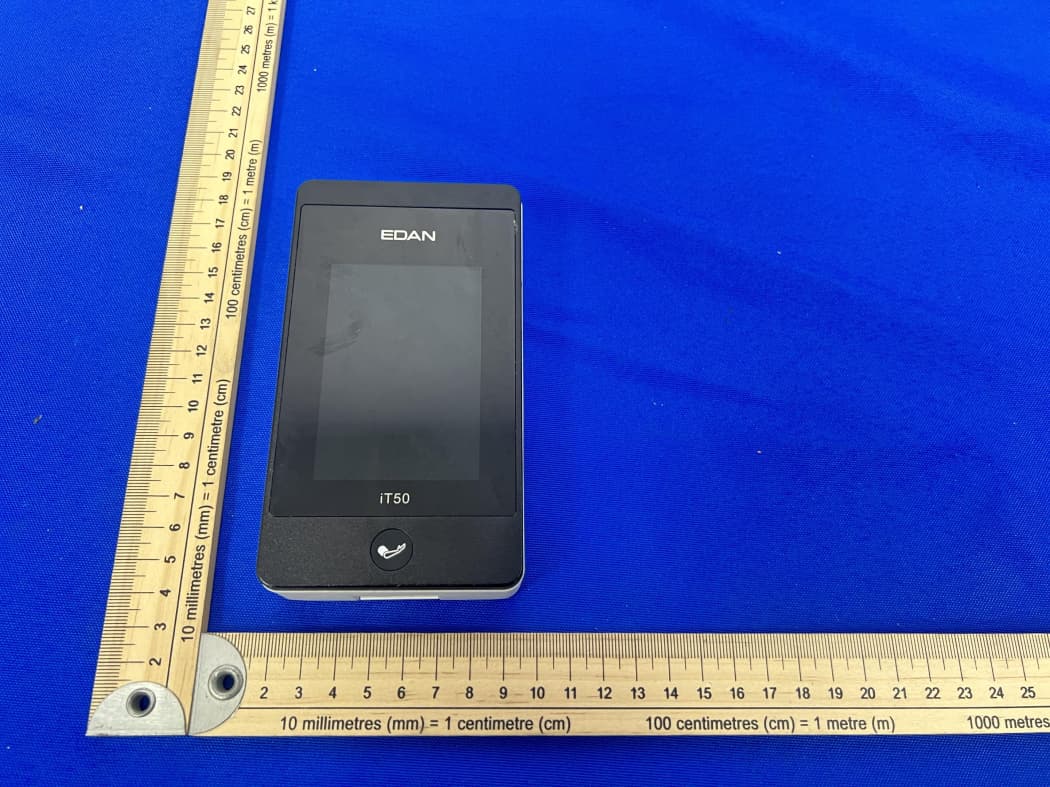
SMQIT50
Jan 30, 2026Telemetry Monitor
Equipment Class
DXX - Part 15 Low Power Communication Device TransmitterSMQIT30
Jan 28, 2026Shenzhen CTL Testing Technology Co., Ltd.
Equipment Class
NII - Unlicensed National Information Infrastructure TX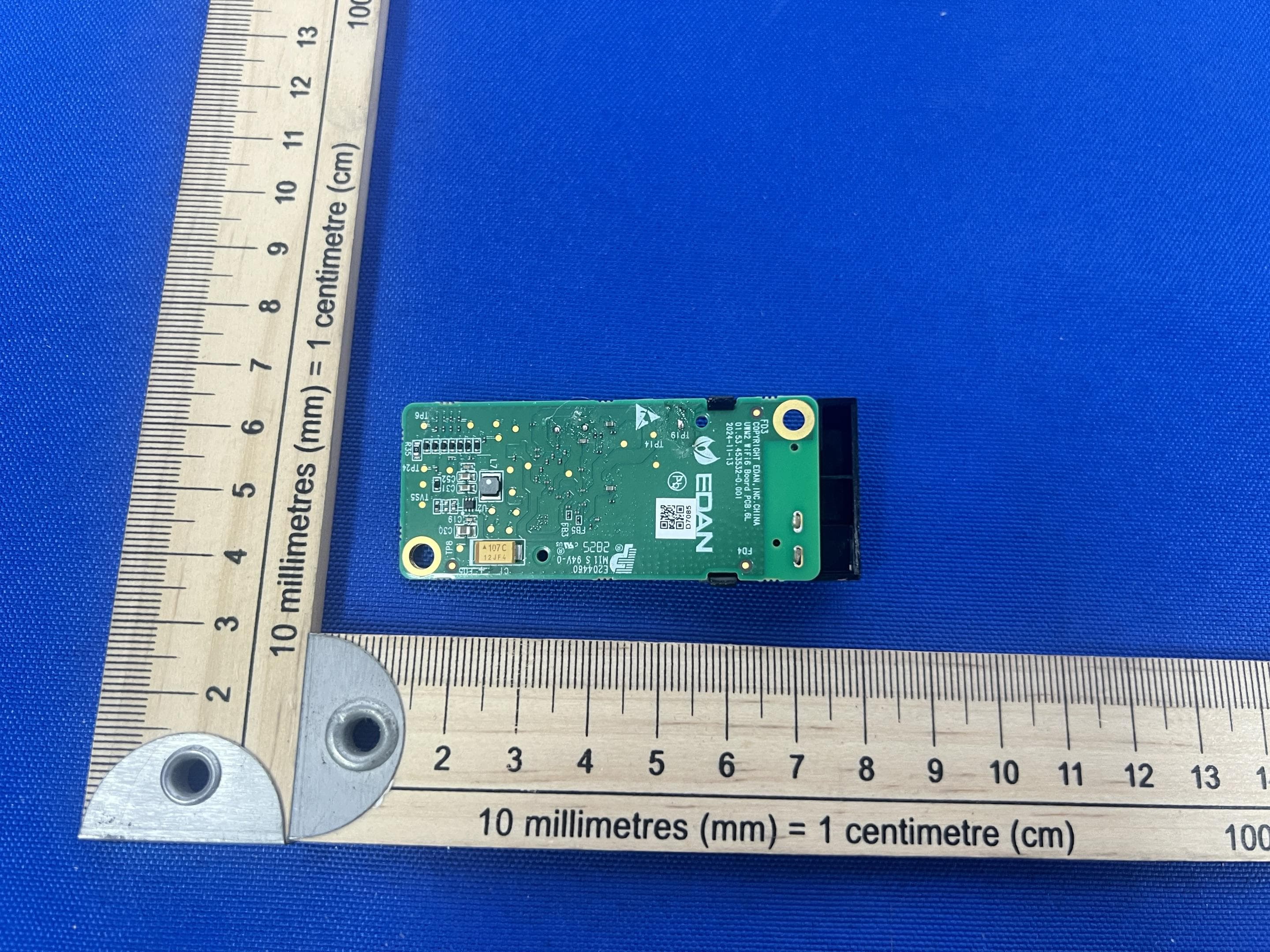
SMQUWM2
Dec 02, 2025WIFI module
Equipment Class
DTS - Digital Transmission System
SMQ-NANOC5
Sep 15, 2024Nano Series Diagnostic Ultrasound Systen
Equipment Class
NII - Unlicensed National Information Infrastructure TX