SN85883Wireless LAN modem
Sagemcom SAS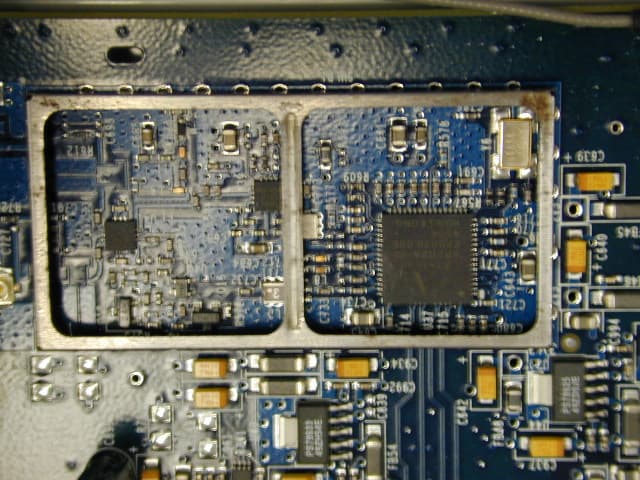
Click to zoom
Application Details
- Equipment Class
- DTS - Digital Transmission System
- Date of Grant
- Oct 20, 2005
- Application Purpose
- Original Equipment
- Date of Application
- Oct 20, 2005
- Equipment Note
- Wireless LAN modem
- Frequency Range
- 2412.00000000 - 2462.00000000
- Company
- Sagemcom SAS
- Country
- France
Documents & Files
Document Text
Text extracted from the exhibit documents filed with the FCC. Open a document above to read the original.
Users Manual
Safety and Certifications 007-9058-001 1 Important Information about the SpeedStream 5883: Installation and Safe Usage Instructions: 1. Place the SpeedStream wireless broadband inte rnet router in an upright horizontal orientation on a flat surface. 2. Connect the manufacturer supplied AC to DC power adapter. The SpeedStream 5883 series router requires the use of a 12 VDC, 1.5 A power adapter. Only use a manufacturer supplied and approved power adapter. 3. Connect the Ethernet cable (provided) to one of the RJ45 ports on the SpeedStream 5883 port labeled "Ethernet/LAN". Then connect the other end of the Ethernet Cable then to the Ethernet port of a computer. Repeat as necessary for the available Ethernet ports. 4. Connect the “WAN” port to a WAN or LAN network device with an Ethernet cable. When using this device, basic sa fety precautions should always be followed to reduce the risk of fire, electric shock, and inju ry to persons including the following: 1. Do not use this product near water and avoid contact with moisture. For example, do not use near a bathtub, wash bowl, kitchen sink , laundry tub, in a wet basement, or near a swimming pool. Care should be taken so that liquids are not spilled on this equipment. 2. Never insert objects into the vents of this equipment as this can result in the risk of electrical shock or fire. 3. This equipment should only be operated from the type of power supply indicated on the marking label. 4. Do not overload wall outlets or extension cords. Doing so can result in the risk of fire or electrical shock. 5. Avoid blocking any vent openings or exhaus t exits on this equipment. Do not place equipment in a built-in installation such as a cabinet that may impede the flow of air through the ventilation openings. 6. The equipment should be situated away from heat sources such as radiators, heat registers, stoves, or other heat producing appliances and equipment. 7. Care should be taken to ensure that the power cord is routed, so it is not likely to be walked on or pinched by items placed upon or next to it. 8. Unplug this equipment before cleaning. Do not use liquid cleaners or aerosol cleaners. Use a damp cloth for cleaning only. 9. This equipment is not user serviceable and is to be serviced by qualified personnel only. Do not disassemble this equipment. If servic e is required, disconnect all power and phones lines from the equipment and co nsult qualified service personnel. Save these Instructions! Federal Communications Commission (FCC) Statements This device complies with Part 15 of the FCC Rules. Operation is subject to the following two conditions: (1) This device may not cause harmful interference, and (2) This device must accept any interference received, including interference that may cause undesired operation. Modifications: You are cautioned that changes or modifica tions not expressly approved by the party responsible for compliance could void your authority to operate the equipment. Safety and Certifications 007-9058-001 2 FCC Responsible Party: Siemens Subscriber Networks, Inc. 4849 Alpha Road Dallas, TX 75244 Phone: 972-852-1000 Radio Frequency Interference Statement Note: This equipment has been tested and found to comply with the limits for a Class B digital device, pursuant to Part 15 of the F CC Rules. These limits are designed to provide reasonable protection against harmf ul interference in a residential installation. This equipment generates, uses and can radiate radi o frequency energy and, if not installed and used in accordance with the instructions, may cause harmful interference to radio communications. However, ther e is no guarantee that interference will not occur in a particular installation. If this equipment does cause harmful interference to radio or television reception, which can be determined by turning the equipment off and on, the user is encouraged to try to correct the interference by one or more of the following measures: 1. Reorient or relocate the receiving antenna. 2. Increase the separation between the equipment and receiver. 3. Connect the equipment into an outlet on a circui t different from that to which the receiver is connected. 4. Consult the dealer or an experi enced radio/TV technician for help. FCC Terminal Equipment Statements This equipment complies with Part 68 of the FCC rules and the requirements adopted by the ACTA. On the bottom side of this equipm ent is a label that contains, among other information, a product identifier in the format US:SN8N5883. If requested, this number must be provided to the Telephone Company. A copy of the Suppliers Declaration of Conformity to the FCC Part 68 and ACTA requirements can be found at: http://www.part68.org. This equipment has a Universal Service Order Code (USOC) of RJ11C, a Facility Interface Code (FIC) of 02LS2, and a Service Order Code (SOC) of 7.0Y. The Telephone Company may request this information when ordering service for this equipment. A plug and jack used to connect this equipment to the premises wiring and telephone network must comply with the applicable FCC Part 68 rules and requirements adopted by the ACTA. A compliant telephone cord and modular plug is provided with this product. It is designed to be connected to a compatible modular jack that is also compliant. If this equipment causes harm to the telephone network, the telephone company will notify you in advance that temporary discontinuance of service may be required. But if advance notice isn't practical, the Telephone Company w ill notify the customer as soon as possible. Also, you will be advised of your right to file a complaint with the FCC if you believe it is necessary. The Telephone Company may make changes to its facilities, equipment, operations or procedures that could affect the operation of the equipment. If this happens the Telephone Company will provide advance not ice so you can make the ne cessary modifications to maintain uninterrupted service. This equipment is not…
Text truncated - open the document above for the full version.
Cover Letter(s)
20 September, 2005 Equipment Autorisation Division Federal Communications Commission 7435 Oakland Mills Road Columbia, MD 21046 FCC ID: SN85883 Product Name: SpeedStream 5883 Request for Confidentiality Pursuant to Sections 0.457 and 0.459 of the commissions rules, we hereby request that the following documents be held confidential: • Schematics and BOM • Block diagram • Operational description These materials contain trade secrets and proprietary information and are not customarily released to the public. The public disclosure of this information might be harmful to the company and provide unjustified benefits to our competitors. Dated this 20th Day ofSeptember 20 05 By: David Light Signature Printed Title: Wireless Engineer On behalf of : Siemens Subscriber Networks Telephone: 972-759-2542
ID Label/Location Info
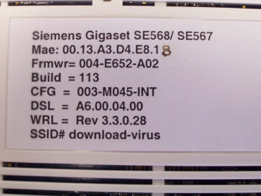
� ������� � � � � EFFICIENT NETWORKS INC. CONFIDENTIALAND PROPRIETARY INFORMATION -- INTERNAL DATA All information set forth in this drawing and all rights in and to all patents, trademarks, copyrights, trade secrets and any and all intellectual property disclosed herein are the sole and executive property of Efficient Networks, Inc. No disclosure of this drawing and/or the information contained herein shall be made to any other person, entity or organization without the express prior written consent of Efficient Networks, Inc. REVDESCRIPTIONDATE . REVISION HISTORY UNLESS OTHERWISE SPECIFIED APPROVALS SCALE: NONE PART NO. ¥ DIMS ARE IN INCHES ¥ TOLERANCES: - ANGLES +/- 1 DEGREE - 2-PLACE DECIMALS +/- .02 - 3-PLACE DECIMALS +/- .010 ¥ PARENTHETICAL INFORMATION FOR REFERENCE ONLY B � �� � � � � � �������� � � � . . . .. . .. . ECOxxxxxxxxx INITIAL RELEASE DRAWN BY: Nathan Belsher ENGR: Nathan Belsher MFG: SAFETY : CM: DATE: 9/22/05 DATE: 9/22/05 DATE: DATE: DATE: SHEET11 . . 763-0093-001 LABEL, CHASSIS, AGENCY APPROVAL, 5883, Generic US REVA 763-0093-001 . � . � . . NOTES: 1. LABEL MATERIAL SHALL BE THERMLfilm SELECT 21940, 2 MIL WHITE POLYESTER OR ULAPPROVED EQUIVALENT. 2. ADHESIVE SHALL BE PERMANENT PSA OR APPROVED EQUIVALENT . 3. PRINTING SHALL BE BLACK, USING RESIN RIBBON OR RIBBON REQUIRED FOR MATERIAL SPECIFIED. 4. TO ENSURE PROPER AND QUALITY PRINTING, THE LABEL SURFACE SHALL BE CLEAN AND FREE OF RESIDUE. Model: 5883 Wireless Broadband Router Part Number: 060-5883-xxx RATING : 12VDC, 1500 mA 5883004DDDRRAAYWWYWW 5. ALLAGENCY CERTIFICATION GRAPHICS AND TEXT SHALLAPPEARAS DEFINED PER DRAWING BELOW. 6. THE BARCODES SHALL BE CODE 39 FORMAT WITH HUMAN READABLE TEXT. 3.0 4.0 MAC: EEEEEEEEEEEE Assembled In CCCCCCC Manufactured In CCCCCCC TEXT FONT ARIAL, BOLD ITALIC 14 PT TEXT FONT ARIAL, BOLD ITALIC 10 PT LABEL EDGE DO NOT PRINT MACADDRESS BARCODE CODE 39 10 MIL MULTIPLIER 2:1 BAR-WIDTH RATIO 0.20 HEIGHT (SEE NOTE 8.) PRODUCT ID. BARCODE CODE 39 10 MIL MULTIPLIER 2:1 BAR-WIDTH RATIO 0.20 HEIGHT (SEE NOTE 10.) TEXT FONT STYLE SHALL BE ARIAL WITH A TEXT SIZE OF 8 PT UNLESS SPECIFIED OTHERWISE. 7. 8. THE MAC ADDRESS BARCODE SHALL BE DETERMINED BY SCANNING THE MAC ADDRESS LABEL ON THE 059- LEVEL, CHASSIS SUB-ASSEMBLY (12 CHARACTERS). 10. THE PRODUCT IDENTIFICATION BARCODE SHALL CONTAIN IN SUCCESSION: 5883 PRODUCT TYPE (FIXED) 004 THREE DIGIT SUFFIX IN PRODUCT PART NUMBER AT 060- LEVEL (FIXED) DDD THREE DIGIT SUFFIX IN PRODUCT PART NUMBER AT 030- LEVEL (SCAN DEFINED) RR CURRENT REVISION LEVEL AT 030- LEVEL (SCAN DEFINED) AA MANUFACTURING SITE CODE AT 030- LEVEL, REFERENCE 007-9050-001 (SCAN DEFINED) Y LAST DIGIT OF YEAR OF MANUFACTURE AT 030- LEVEL (SCAN DEFINED) WW WEEK NUMBER OF YEAR OF MANUFACTURE AT 030- LEVEL (SCAN DEFINED) Y LAST DIGIT OF YEAR OF ASSEMBLY/FINAL PROGRAMMING AT 060- LEVEL (VARIABLE) WW WEEK NUMBER OF YEAR OF ASSEMBLY/PROGRAMMING AT 060- LEVEL (VARIABLE) FORM: 5883004DDDRRAAYWWYWW (20 ALPHANUMERIC CHARACTERS) 9. REFERENCE 007-9050-001, MANUFACTURING SITE CODE LIST, FOR "Assembled in ........." AND "Mfg. in .........." INFORMATION. SEE NOTE 9. TEXT FONTARIAL, BOLD, 7 PT TestedTo Comply With FCC Standards FOR HOME OR OFFICE USE FCC: SN85883 � � � � � � TEXT FONTARIAL, BOLD, 6 PT ICES-003 Class B IC:267AJ-5883 The label mounts on the bottom of the device. Due to venting required in the plastics, the label is too small to include the FCC Part 15 conditional statement. This statement is placed in the Safety and Regulatory Information Sheet provided to the User. Label on Bottom
ID Label/Location Info
The label mounts on the bottom of the device. Due to venting required in the plastics, the label is too small to include the FCC Part 15 conditional statement. This statement is placed in the Safety and Regulatory Information Sheet provided to the User. Label location
RF Exposure Info
Prediction of MPE limit at a given distance Equation from page 18 of OET Bulletin 65, Edition 97-01 where:S = power densit y P = power input to the antenna G = power gain of the antenna in the direction of interest relative to an isotropic radiator R = distance to the center of radiation of the antenna Maximum peak output power at antenna input terminal :22.62(dBm) Maximum peak output power at antenna input terminal:182.81(mW) Antenna gain(typical):5(dBi) Maximum antenna gain:3.162278(numeric) Prediction distance:20(cm) Prediction frequency:2400(MHz) MPE limit for uncontrolled exposure at prediction frequency:1(mW/cm^2) Power density at prediction frequency:0.115009(mW/cm^2) 2 4R PG S π =
Test Report
Nemko Test Report: 5L0270RUS1Rev1 Applicant: Siemens Subscriber Networks, Inc. 4849 Alpha Rd. Dallas, Texas 75244 Equipment Under Test: SpeedStream 5883 (E.U.T.) 060-5883-0XX In Accordance With: FCC Part 15, Subpart C, 15.247 Digital Transmission System Transmitter Tested By: Nemko Dallas Inc. 802 N. Kealy Lewisville, Texas 75057-3136 Authorized By: John Fish, EMC Engineer Date: 20 July, 2005 Nemko Dallas FCC PART 15, SUBPART C Digital Transmission Systems EQUIPMENT: SpeedStream 5883 Test Report No.:5L0270RUS1Rev1 Page 2 of 62 Table of Contents Section 1. Summary of Test Results ......................................................... 3 Section 2. Equipment Under Test (E.U.T.) ................................................ 5 Section 3. Powerline Conducted Emissions .............................................. 8 Section 4. Occupied Bandwidth............................................................... 12 Section 5. Maximum Peak Output Power ................................................ 20 Section 6 Spurious Emissions at Antenna Terminals ............................. 21 Section 7. Radiated Emissions ................................................................ 32 Section 8. Peak Power Spectral Density ................................................. 37 Section 9. Test Equipment List ................................................................. 41 ANNEX A - TEST DETAILS ....................................................................... 49 ANNEX B - TEST DIAGRAMS ................................................................... 60 Nemko Dallas FCC PART 15, SUBPART C Digital Transmission Systems EQUIPMENT: SpeedStream 5883 Test Report No.:5L0270RUS1Rev1 Page 3 of 62 Section 1. Summary of Test Results Manufacturer: Siemens Subscriber Networks, LLC Model No.: SpeedStream 5883 Part. No.: 060-5883-0XX Serial No.: 303 General: All measurements are traceable to national standards. These tests were conducted on a sample of the equipment for the purpose of demonstrating compliance with Part 15, Subpart C, Paragraph 15.247 for Digital Transmission Systems. Radiated tests were conducted is accordance with ANSI C63.4-2002. Radiated emissions are made on an open area test site. A description of the test facility is on file with the FCC. New Submission Production Unit Class II Permissive Change Pre-Production Unit THIS TEST REPORT RELATES ONLY TO THE ITEM(S) TESTED. THE FOLLOWING DEVIATIONS FROM, ADDITIONS TO, OR EXCLUSIONS FROM THE TEST SPECIFICATIONS HAVE BEEN MADE. See “ Summary of Test Data”. NVLAP LAB CODE: 100426-0 Nemko Dallas Inc. authorizes the above named company to reproduce this report provided it is reproduced in its entirety and for use by the company’s employees only. Any use which a third party makes of this report, or any reliance on or decisions to be made based on it, are the responsibility of such third parties. Nemko Dallas Inc. accepts no responsibility for damages, if any, suffered by any third party as a result of decisions made or actions based on this report. This report applies only to the items tested. Nemko Dallas FCC PART 15, SUBPART C Digital Transmission Systems EQUIPMENT: SpeedStream 5883 Test Report No.:5L0270RUS1Rev1 Page 4 of 62 Summary Of Test Data NAME OF TEST PARA. NO. RESULT Powerline Conducted Emissions 15.207(a) Complies Minimum 6 dB Bandwidth 15.247(a)(2) Complies Maximum Peak Power Output 15.247(b)(1) Complies Spurious Emissions (Antenna Conducted) 15.247(c) Complies Spurious Emissions (Restricted Bands) 15.247(c) Complies Peak Power Spectral Density 15.247(d) Complies Footnotes: Nemko Dallas FCC PART 15, SUBPART C Digital Transmission Systems EQUIPMENT: SpeedStream 5883 Test Report No.:5L0270RUS1Rev1 Page 5 of 62 Section 2. Equipment Under Test (E.U.T.) General Equipment Information Frequency Band: 2412 to 2462 MHz Antenna: 5 dBi gain Channel Spacing: 5 MHz User Frequency Adjustment: Software controlled Nemko Dallas FCC PART 15, SUBPART C Digital Transmission Systems EQUIPMENT: SpeedStream 5883 Test Report No.:5L0270RUS1Rev1 Page 6 of 62 Configuration of Equipment EQUIPMENT CONFIGURATION LIST (HARDWARE/PERIPHERALS): on 060-5883-xxx Place an "*" next to EUT and any item that is part of the EUT. Item*Rev. (A) *n/a (B) * AC WallWart Adapter(Euro)GCIAM-1201000Vn/an/an/a (C) * AC WallWart Adapter(Dom.)Ten-PaoS024AU1200150n/an/an/a (D) MonitorGatewayE5005HDA7JB001012n/aIAWE5005 (E) ComputerDellMMSENUTBn/an/a (F) KeyboardDellSK-8000CN-035KKW-38844-09D-B 4A00 n/a (G) MouseLogitech-DellM-S34LZA54814607n/aDZL210472 (H) Laptop ComputerDellPPL12800-966-3390n/an/a (I) AC Adapter for Laptop Comp.DellAA20031CN09364U-1629113J0DQN A00 n/a ¹ FCC ID STATUS 1. FCC DOC3. None - (If performing FCC testing, contact lab manager) 2. FCC A/B Verification4. Certification (include FCC ID in parenthesis) INTER-CONNECTION CABLES: Place an "*" next to EUT and any item that is part of the EUT. Item*Ln (m)Term ²Qty. (1) 100m35 (2) (3) (4) (5) (6) (7) (8) (9) ² TERMINATION 1. Peripheral4. Resistive 2. Loopback5. Remote Equipment 3. EUT6. Othe r Generic DescriptionManufacturerModel No.Serial #FCC ID Status¹ 5883 ModemSiemens/Efficient060-5883-1xx/ -0xxSN#303 or 304, or 305n/a Cable TypeManufacturerShield CAT5EGeneral Cableno Nemko Dallas FCC PART 15, SUBPART C Digital Transmission Systems EQUIPMENT: SpeedStream 5883 Test Report No.:5L0270RUS1Rev1 Page 7 of 62 Description of EUT Wireless 802.11b/g Ethernet modem. System Diagram A H D E F 1 G I BC Nemko Dallas FCC PART 15, SUBPART C Digital Transmission Systems EQUIPMENT: SpeedStream 5883 Test Report No.:5L0270RUS1Rev1 Page 8 of 62 Section 3. Powerline Conducted Emissions NAME OF TEST: Powerline Conducted Emissions PARA. NO.: 15.207(a) TESTED BY: Arturo Ruvalcaba DATE: 6/8/2005 Test Results: Complies. Measurement Data: See attached plots. Measurement Uncertainty: +/- 2.27 dB The worst-case emission is 50.5dBμV at 0.153 MHz on the Neutral side of the line. This is 5.3 dB below the average specification limit of 55.8dBμV. N…
Text truncated - open the document above for the full version.
Contact Information
Applicant
Jacques LE ROUX(R&D General Methods Dpt Manager)
Technical Contact
Test Firm
Nemko Dallas, Inc.Michael Cantwell
Technical Specifications
| # | Rule Parts | Frequency Range | Power Output |
|---|---|---|---|
| 1 | 15C | 2.41 GHz - 2.46 GHz | 183.00 mW |
Other Applications from Sagemcom SAS
SN8H650
Oct 19, 2006Broadband Wireless Gateway
Equipment Class
DTS - Digital Transmission System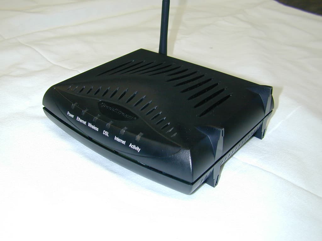
SN8N652
Aug 24, 2005Wireless DSL Modem
Equipment Class
DTS - Digital Transmission System
SN8R651
Jun 13, 2005802.11 b/g Wireless DSL Modem
Equipment Class
DTS - Digital Transmission System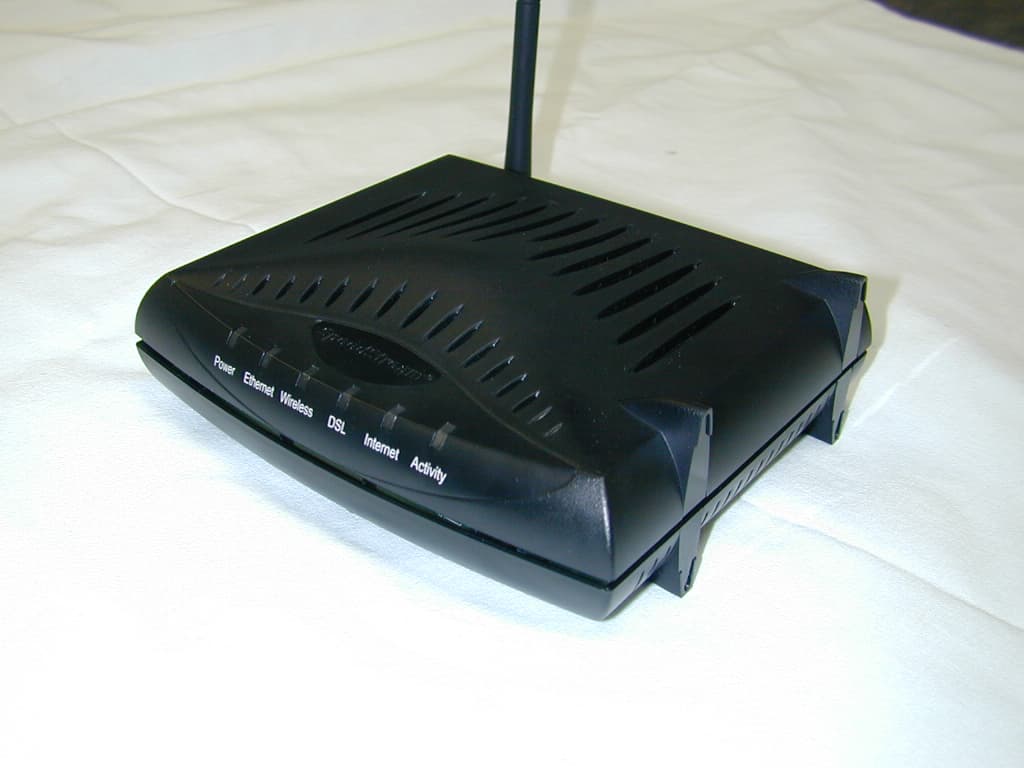
SN8N651
Jan 20, 2005Wireless DSL Modem
Equipment Class
DTS - Digital Transmission System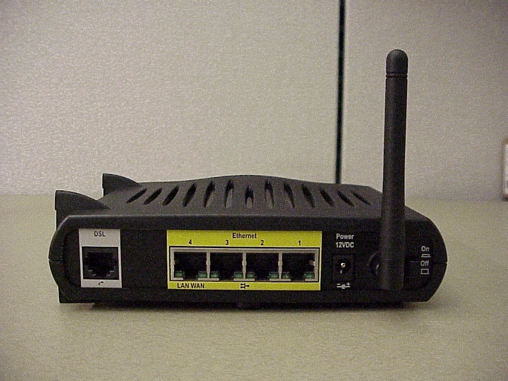
SN8N650A01
Nov 02, 2004Wireless DSL Modem
Equipment Class
DTS - Digital Transmission System