SN8N650A01Wireless DSL Modem
Sagemcom SAS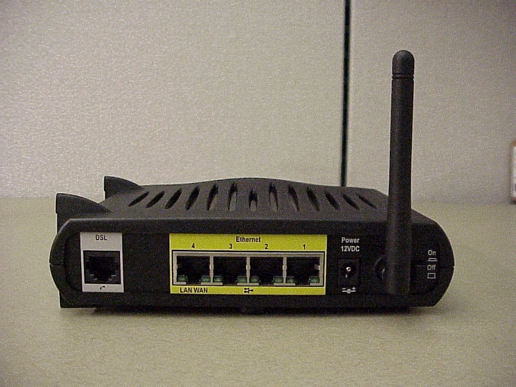
Click to zoom
Application Details
- Equipment Class
- DTS - Digital Transmission System
- Date of Grant
- Nov 02, 2004
- Application Purpose
- Original Equipment
- Date of Application
- Nov 02, 2004
- Equipment Note
- Wireless DSL Modem
- Frequency Range
- 2412.00000000 - 2462.00000000
- Company
- Sagemcom SAS
- Country
- France
Documents & Files
Document Text
Text extracted from the exhibit documents filed with the FCC. Open a document above to read the original.
Users Manual
SpeedStream® Residential Family User’s Guide 6500 Series Part No. 007-6770-001 Residential Gateway Family User’s Guide © Copyright 2004, Siemens Subscriber Network. All rights reserved. Printed in the U.S.A. Product names mentioned herein may be trademarks and/or registered trademarks of their respective companies. Siemens Subscriber Networks shall not be liable for technical or editorial errors or omissions in this document; nor for incidental or consequential damages resulting from the furnishing, performance, or use of this material. Siemens Subscriber Networks – End User Software License and Limited Warranty INSTALLATION OF THE HARDWARE AND SOFTWARE PROVIDED BY SIEMENS SUBSCRIBER NETWORKS (SIEMENS) CONSTITUTES ACCEPTANCE BY YOU OF THE TERMS OF THE FOLLOWING SOFTWARE LICENSE AND LIMITED WARRANTY. IF YOU DO NOT ACCEPT THESE TERMS, PLEASE RETURN THE HARDWARE AND SOFTWARE IN ITS ORIGINAL PACKAGING TO THE STORE OR OTHER VENDOR FROM WHICH YOU PURCHASED IT FOR A FULL REFUND OF THE PURCHASE PRICE. The following describes your license to use the software (the “Software”) that has been provided with your SIEMENS DSL customer premises equipment (“Hardware”) and the limited warranty that SIEMENS provides on its Software and Hardware. Software License The Software is protected by copyright laws and international copyright treaties. The Software is licensed and not sold to you. Accordingly, while you own the media (CD ROM or floppy disk) on which the Software is recorded, SIEMENS retains ownership of the Software itself. 1. Grant of License. You may install and use one (and only one) copy of the Software on the computer on which the Hardware is being installed. If the Hardware is being installed on a network, you may install the Software on the network server or other server-side device on which the Hardware is being installed and onto the client-side devices connected to the network as necessary. 2. Restrictions. The license granted is a limited license. You may NOT: sublicense, assign, or distribute copies of the Software to others; decompile, reverse engineer, disassemble or otherwise reduce the Software or any part thereof to a human perceivable form; modify, adapt, translate or create derivative works based upon the Software or any part thereof; or rent, lease, loan or otherwise operate for profit the Software. 3. Transfer. You may transfer the Software only where you are also transferring the Hardware. In such cases, you must remove all copies of the Software from any devices onto which you have installed it, and must ensure that the party to whom you transfer the Hardware receives this License Agreement and Limited Warranty. 4. Upgrades Covered. This license covers the Software originally provided to you with the Hardware, and any additional software that you may receive from SIEMENS, whether delivered via tangible media (CD ROM or floppy disk), down loaded from SIEMENS or delivered through customer support. Any such additional software shall be considered “Software” for all purposes under this License. 5. Export Law Assurance. You acknowledge that the Software may be subject to export control laws and regulations of the U.S.A. You confirm that you will not export or re-export the Software to any countries that are subject to export restrictions. 6. No Other Rights Granted. Other than the limited license expressly granted herein, no license, whether express or implied, by estoppel or otherwise, is granted to any copyright, patent, trademark, trade secret, or other proprietary rights of SIEMENS. 7. Termination. Without limiting SIEMENS’s other rights, SIEMENS may terminate this license if you fail to comply with any of these provisions. Upon termination, you must destroy the Software and all copies thereof. Limited Warranty The following limited warranties provided by SIEMENS extend to the original end user of the Hardware/licensee of the Software and are not assignable or transferable to any subsequent purchaser/licensee. 1. Hardware. SIEMENS warrants that the Hardware will be free from defects in materials and workmanship and will perform substantially in compliance with the user documentation relating to the Hardware for a period of one year from the date the original end user received the Hardware. 2. Software. SIEMENS warrants that the Software will perform substantially in compliance with the end user documentation provided with the Hardware and Software for a period of ninety days from the date the original end user received the Hardware and Software. The end user is responsible for the selection of hardware and software used in the end user’s systems. Given the wide range of third-party hardware and applications, SIEMENS does not warrant the compatibility or uninterrupted or error free operation of our Software with the end user’s system. 3. Exclusive Remedy. Your exclusive remedy and SIEMENS’s exclusive obligation for breach of this limited warranty is, in SIEMENS’s sole option, either (a) a refund of the purchase price paid for the Hardware/Software or (b) repair or replacement of the Hardware/Software with new or remanufactured products. Any replacement Hardware or Software will be warranted for the remainder of the original warranty period or thirty (30) days, which ever is longer. 4. Warranty Procedures. If a problem develops during the limited warranty period, the end user shall follow the procedure outlined below: A. Prior to returning a product under this warranty, the end user must first call SIEMENS at (888) 286-9375, or send an email to SIEMENS at [email protected] to obtain a return materials authorization (RMA) number. RMAs are issued between 8:00 a.m. and 5:00 p.m. Central Time, excluding weekends and holidays. The end user must provide the serial number(s) of the products in order to obtain an RMA. B. After receiving an RMA, the end user shall ship the product, including power supplies and cable, where applicable, freight or postage prepaid and insured, to SIEMENS …
Text truncated - open the document above for the full version.
Users Manual
Residential Gateway Family User’s Guide Configuring Advanced Features IP Network The Gateway provides the flexibility to use different ranges of IP addresses to be assigned by the DHCP Server housed in the Gateway. DHCP (Dynamic Host Configuration Protocol) allows computers to obtain either permanent or temporary IP addresses from a central server. To configure the IP network option: 1. Click the Configure the local SpeedStream Gateway IP Network hyperlink. This displays the “SpeedStream Gateway IP Network” window. 2. Select a range from the displayed options and click Save Settings. Be sure to select an IP address range that is not in conflict with any existing devices. 3. Optionally, click the Custom Settings hyperlink for advanced configuration. Please contact your ISP for more information on configuring the options for custom settings. 45 Residential Gateway Family User’s Guide Configuring Advanced Features Server Ports Common applications such as HTTP (Web site traffic), FTP, and Telnet use pre-defined incoming port numbers for compatibility with other services. If you wish to change the ports used by these applications you may do so using this option. This feature is recommended for use by advanced users only. To configure the server port option: 1. Click the Configure the Local SpeedStream Gateway Server Ports hyperlink. This displays the “SpeedStream Gateway Server Ports” window. 2. Optionally, type a port number in HTTP. The default port for this field is 80. 3. Optionally, type a port number in FTP. The default port for this field is 21. 4. Optionally, type a port number in Telnet. The default port for this field is 23. 5. Click Apply. This displays the “Your settings have been saved” window. 6. Optionally, click Reboot if you wish for the settings to immediately be implemented. The system responds by restarting your Gateway. 46 Residential Gateway Family User’s Guide Configuring Advanced Features LAN/WAN Port If your Gateway contains four Ethernet ports, Ethernet port #4 can be used as either a LAN (network) port or as a WAN (Internet connection) port. Select the appropriate option to define whether the port is used as a fourth local network port or as a connection for another broadband device. Note: For configuration of the port as a WAN port, you may be required to consult your Internet Service Provider for the appropriate settings. To configure the LAN/WAN port: 1. Click the Configure the Local SpeedStream Gateway LAN/WAN Port hyperlink. This displays the “SpeedStream Gateway LAN/WAN Port” window. 2. Select one of the following options: • LAN (Local Area Network) Use the port as a connection to the network located in your home or premises. • WAN (Wide Area Network) Use the port as a connection to a large connected network such as the Internet that is spread over a large geographic area. If you select the WAN option, please contact your ISP for instructions on how to configure this option. 3. Click Apply. 47 Residential Gateway Family User’s Guide Configuring Advanced Features Wireless Network Configure the wireless network using this option. The wireless settings on the Gateway must match those of any wireless clients on your network. To configure the wireless network: 1. Click the Configure the Local SpeedStream Gateway Wireless Network hyperlink. This displays the “Wireless Summary” window. 2. Click Begin Wireless Wizard. This displays the “Wireless Setup Configuration” window. 3. Select Enable to enable the Wireless Interface. 4. Type your wireless network ID in SSID (Service Set Identifier). 5. Optionally, select a channel ID from the Channel drop-down menu. This is typically done if you experience any interference with your wireless Gateway. 6. Click Next. This displays the “Wireless Security Configuration” window. 48 Residential Gateway Family User’s Guide Configuring Advanced Features Set the wireless security level from the “Wireless Security Configuration” window. All wireless devices attached to the Gateway MUST have the same wireless security settings for your network to have proper communications and security. 7. From the Security Mode drop-down menu, select one of the following options: • WEP 64-bits Wireless Equivalency Privacy. WEP security offers the same security offered by a wired LAN with encrypted packets. This option offers 64-bit encryption, which is the least secure WEP option. Please see the section in this document titled Wireless Setup WEP 64-Bit Option (Advanced Home Networking) for more information. • WEP 128-bits Wireless Equivalency Privacy. WEP security offers the same security offered by a wired LAN with encrypted packets. This option offers 128-bit encryption, which is a most secure WEP option. Please see the section in this document titled Wireless Setup WEP 128-Bit Option (Advanced Home Networking) for more information. • WPA PSK Wi-Fi Protected Access. WPA security changes encryption keys after a specified amount of time. This is the most secure option for wireless networks. Please see the section in this document titled Wireless Setup WPA PSK Option (Advanced Home Networking) for more information. 8. Optionally, select the Enable SSID Broadcast option so wireless users can see the existence of the wireless Gateway with the associated SSID. 49 Residential Gateway Family User’s Guide Configuring Advanced Features Wireless Setup WEP 64-Bit Option (Advanced Home Network) WEP security offers the same security offered by a wired LAN with encrypted packets. This section assumes you currently have the “Wireless Security Configuration” window displayed on your computer. To use the WEP 64-bit option: 1. From the “ Wireless Security Configuration” window, select WEP 64-bits from the Security Mode drop-down menu. 2. Click Next. This displays the “Wireless 64-bit WEP Configuration” window. 3. Select one of the following Authentication options: • Open System Open system keys are always authenticated at the device level. After authentication, data is e…
Text truncated - open the document above for the full version.
Users Manual
Safety and Certifications 007-0650-001 1 Important Information about the Sp eedStream 6520, SpeedStream 6515: Installation and Safe Usage Instructions: 1. Place the SpeedStream ADSL gateway in an upright horizontal orientation on a flat surface. 2. Connect the manufacturer supplied AC to DC power adapter. The SpeedStream 6xxx series gateways require the use of a 12 VDC, 1 A power adapter. Only use a manufacturer supplied and approved power adapter. 3. Connect the Ethernet cable (provided) to the RJ45 port on the SpeedStream ADSL Gateway labeled "Ethernet". Then connect the other end of the Ethernet Cable then to the Ethernet port of a computer. Repeat as necessary for the available Ethernet ports. 4. If a USB port is available, connect the “B” end of the provided USB cable to the port on the SpeedStream ADSL Gateway labeled "USB". Then connect the “A” end of the USB Cable to the USB host port of a computer. 5. Connect the provided DSL Cable to the port on the SpeedStream ADSL Gateway labeled "DSL". Connect the other end of the DSL Cable to a standard Phone Jack. Always use a DSL cable with a minimum wire gauge of 26AWG. 6. If using a USB port, use the SpeedStream CD to configure the computer’s USB connection. When using this device, basic safety precautions should always be followed to reduce the risk of fire, electric shock, and injury to persons including the following: 1. Do not use this product near water and avoid contact with moisture. For example, do not use near a bathtub, wash bowl, kitchen sink, laundry tub, in a wet basement, or near a swimming pool. Care should be taken so that liquids are not spilled on this equipment. 2. Never insert objects into the vents of this equipment as this can result in the risk of electrical shock or fire. 3. This equipment should only be operated from the type of power supply indicated on the marking label. 4. Do not overload wall outlets or extension cords. Doing so can result in the risk of fire or electrical shock. 5. Avoid blocking any vent openings or ex haust exits on this equipment. Do not place equipment in a built-in installation such as a c abinet that may impede the flow of air through the ventilation openings. 6. The equipment should be situated away from heat sources such as radiators, heat registers, stoves, or other heat producing appliances and equipment. 7. Care should be taken to ensure that the power cord is routed, so it is not likely to be walked on or pinched by items placed upon or next to it. 8. Unplug this equipment before cleaning. Do not use liquid cleaners or aerosol cleaners. Use a damp cloth for cleaning only. 9. This equipment is not user serviceable and is to be serviced by qualified personnel only. Do not disassemble this equipment. If servic e is required, disconnect all power and phones lines from the equipment and cons ult qualified service personnel. Save these Instructions! Federal Communications Commission (FCC) Statements This device complies with Part 15 of the FCC Ru les. Operation is subject to the following two conditions: (1) This device may not caus e harmful interference, and (2) This device must accept any interferenc e received, including interference that may cause undesired operation. Safety and Certifications 007-0650-001 2 Modifications: You are cautioned that changes or modifica tions not expressly approved by the party responsible for compliance could void your authority to operate the equipment. FCC Responsible Party: Siemens Subscriber Networks, Inc. 4849 Alpha Road Dallas, TX 75244 Phone: 972-852-1000 Radio Frequency Interference Statement Note: This equipment has been tested and found to comply with the limits for a Class B digital device, pursuant to Part 15 of the FCC Rules. These limits are designed to provide reasonable protection against harmf ul interference in a residential installation. This equipment generates, uses and can radiate radio frequency energy and, if not installed and used in accordance with the instructions, may cause harmful interference to radio communications. However, there is no guarantee that interference will not occur in a particular installation. If this equipment does cause harmful interference to radio or television reception, which can be determined by turning the equipment off and on, the user is encouraged to try to correct the interference by one or more of the following measures: 1. Reorient or relocate the receiving antenna. 2. Increase the separation between the equipment and receiver. 3. Connect the equipment into an outlet on a circui t different from that to which the receiver is connected. 4. Consult the dealer or an experienc ed radio/TV technician for help. FCC Terminal Equipment Statements This equipment complies with Part 68 of the FCC rules and the requirements adopted by the ACTA. On the bottom side of this equipment is a label that contains, among other information, a product identifier in the format US:AAAEQ##TXXXX. If requested, this number must be provided to the Telephone Company. A copy of the Suppliers Declaration of Conformity to the FCC Part 68 and ACTA requirements can be found at: http://www.part68.org. This equipment has a Universal Service Order Code (USOC) of RJ11C, a Facility Interface Code (FIC) of 02LS2, and a Service Order Code (SOC) of 7.0Y. The Telephone Company may request this information when ordering service for this equipment. A plug and jack used to connect this equipm ent to the premises wiring and telephone network must comply with the applicable FCC Part 68 rules and requirements adopted by the ACTA. A compliant telephone cord and modular plug is provided with this product. It is designed to be connected to a compatible modular jack that is also compliant. If this equipment causes harm to the tel ephone network, the telephone company will notify you in advance that temporary discontinuance of service may be required. But if advance notice isn't practical, the Telephone Company will notify the customer as soon a…
Text truncated - open the document above for the full version.
Cover Letter(s)
1 October, 2004 Equipment Authoriz ation Division Federal Communications Commission 7435 Oakland Mills Road Columbia, MD 21046 FCC ID: SN8N650A01 Product Name: SpeedStream 6520 and SpeedStream 6515 Request for Confidentiality Pursuant to Sections 0.457 and 0.459 of the commissions rules, we hereby request that the following documents be held confidential: • Schematics • Block diagram • Parts List These materials contain trade secrets and proprietary information and are not customarily released to the public. The public disclosure of this information might be harmful to the company and provide unjustified benefits to our competitors. Dated this 1 st Day of October 20 04 By: Tom Tidwell Signature Printed Title: Frontline Manager On behalf of : Siemens Subscriber Networks Telephone: 972-759-2542
ID Label/Location Info
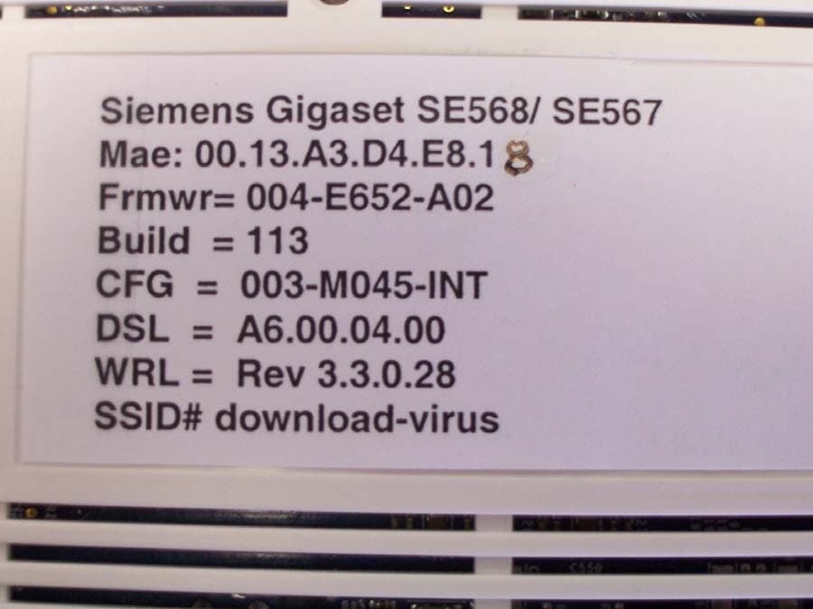
1345678 B A C D Siemens Subscriber Networks, INC. CONFIDENTIAL AND PROPRIETARY INFORMATION -- INTERNAL DATA All information set forth in this drawing and all rights in and to all patents, trademarks, copyrights, trade secrets and any and all intellectual property disclosed herein are the sole and executive property of Siemens Subscriber Networks, Inc. No disclosure of this drawing and/or the information contained herein shall be made to any other person, entity or organization without the express prior written consent of Siemens Subscriber Networks, Inc. REVDESCRIPTIONDATE REVISION HISTORY UNLESS OTHERWISE SPECIFIED APPROVALS SCALE: NONE PART NO. ¥ DIMS ARE IN INCHES ¥ TOLERANCES: - ANGLES +/- 1 DEGREE - 2-PLACE DECIMALS +/- .02 - 3-PLACE DECIMALS +/- .010 ¥ PARENTHETICAL INFORMATION FOR REFERENCE ONLY B SIZE B A C D 21345678 SpeedStream® 6520 Wireless ADSL Gateway Part Number: 060-N650-A01 1.0 09/30/04 ECO204xxx INITIAL RELEASE DRAWN BY: BOB ZMUDKA ENGR: BOB ZMUDKA MFG: SAFETY: CM: DATE: 09/30/04 DATE: 09/30/04 DATE: DATE: DATE: SHEET 1 1OF 763-0074-001 LABEL, CHASSIS, AGENCY APPROVAL, N650-A01 REV 1.0 763-0074-001 NOTES: 1. LABEL MATERIAL SHALL BE THERMLfilm SELECT 21940, 2 MIL WHITE POLYESTER WITH 1 MIL CLEAR THERMAL TRANSFER POLYESTER LAMINATE OR UL APPROVED EQUIVALENT. 2. ADHESIVE SHALL BE PERMANENT PSA OR APPROVED EQUIVALENT. 3. PRINTING SHALL BE BLACK, USING RESIN RIBBON OR RIBBON REQUIRED FOR MATERIAL SPECIFIED. 4. TO ENSURE PROPER AND QUALITY PRINTING, THE LABEL SURFACE SHALL BE CLEAN AND FREE OF RESIDUE. RATING:12VDC, 1.0 A C - + 5. ALL AGENCY CERTIFICATION GRAPHICS AND TEXT SHALL APPEAR AS DEFINED PER DRAWING BELOW. Mfg. In CCCCCCC LABEL EDGE DO NOT PRINT TEXT FONT STYLE SHALL BE ARIAL WITH A TEXT SIZE OF 6 PT UNLESS SPECIFIED OTHERWISE. 6. 3.00 1.00 207647 Assembled In CCCCCCC TEXT FONT ARIAL, BOLD ITALIC, 7 PT TEXT FONT ARIAL, BOLD ITALIC, 10 PT FCC ID: SN8N650A01 US: SSNDLNANN650A01 0470
ID Label/Location Info
1345678 B A C D Siemens Subscriber Networks, INC. CONFIDENTIAL AND PROPRIETARY INFORMATION -- INTERNAL DATA All information set forth in this drawing and all rights in and to all patents, trademarks, copyrights, trade secrets and any and all intellectual property disclosed herein are the sole and executive property of Siemens Subscriber Networks, Inc. No disclosure of this drawing and/or the information contained herein shall be made to any other person, entity or organization without the express prior written consent of Siemens Subscriber Networks, Inc. REVDESCRIPTIONDATE REVISION HISTORY UNLESS OTHERWISE SPECIFIED APPROVALS SCALE: NONE PART NO. ¥ DIMS ARE IN INCHES ¥ TOLERANCES: - ANGLES +/- 1 DEGREE - 2-PLACE DECIMALS +/- .02 - 3-PLACE DECIMALS +/- .010 ¥ PARENTHETICAL INFORMATION FOR REFERENCE ONLY B SIZE B A C D 21345678 SpeedStream® 6515 Wireless ADSL Gateway Part Number: 060-N550-A01 1.0 09/30/04 ECO204xxx INITIAL RELEASE DRAWN BY: BOB ZMUDKA ENGR: BOB ZMUDKA MFG: SAFETY: CM: DATE: 10/20/04 DATE: 10/20/04 DATE: DATE: DATE: SHEET 1 1OF 763-0074-002 LABEL, CHASSIS, AGENCY APPROVAL, N550-A01 REV 1.0 763-0074-002 NOTES: 1. LABEL MATERIAL SHALL BE THERMLfilm SELECT 21940, 2 MIL WHITE POLYESTER WITH 1 MIL CLEAR THERMAL TRANSFER POLYESTER LAMINATE OR UL APPROVED EQUIVALENT. 2. ADHESIVE SHALL BE PERMANENT PSA OR APPROVED EQUIVALENT. 3. PRINTING SHALL BE BLACK, USING RESIN RIBBON OR RIBBON REQUIRED FOR MATERIAL SPECIFIED. 4. TO ENSURE PROPER AND QUALITY PRINTING, THE LABEL SURFACE SHALL BE CLEAN AND FREE OF RESIDUE. RATING:12VDC, 1.0 A C - + 5. ALL AGENCY CERTIFICATION GRAPHICS AND TEXT SHALL APPEAR AS DEFINED PER DRAWING BELOW. Mfg. In CCCCCCC LABEL EDGE DO NOT PRINT TEXT FONT STYLE SHALL BE ARIAL WITH A TEXT SIZE OF 6 PT UNLESS SPECIFIED OTHERWISE. 6. 3.00 1.00 207647 Assembled In CCCCCCC TEXT FONT ARIAL, BOLD ITALIC, 7 PT TEXT FONT ARIAL, BOLD ITALIC, 10 PT FCC ID: SN8N650A01 US: SSNDLNANN650A01 0470
Operational Description
OPERATIONAL DESCRIPTION SpeedStream 6520 The Speedstream 6520 is a wireless DSL modem/router with 4 Ethernet ports and a USB port for connection to a Personal Computer. The wireless interface of the modem is compliant with the IEEE 802.11B and IEEE 802.11G interface standards. The radio circuit is built on the Texas Instruments TNETW2522M integrated radio chip. The radio operates on channels 1 – 11 (2412 – 2462 MHz). The transmit antenna is attaches to the main PC board via a non-standard miniature coaxial connector. The antenna is not detachable by the user. RF Output Power: 100 mW (+20 dBm) Antenna Type: Monopole Antenna Gain: 2dBi Type of modulation: DPSK, CCK, DQPSK, and OFDM Data Rates: 11 Mbps, 54 Mbps Duty Cycle: 50% TDD (Time Division Duplex) Channels of Operation: Channel Frequency (MHz) 1 2412 2 2417 3 2422 4 2427 5 2432 6 2437 7 2442 8 2447 9 2452 10 2457 11 2462 SpeedStream 6515 The SpeedStream 6515 is identical to the 6520 model except that the USB connector and components related to the USB are removed. The radio circuitry is identical.
RF Exposure Info
Prediction of MPE limit at a given distance Equation from page 18 of OET Bulletin 65, Edition 97-01 where:S = power density P = power input to the antenna R = distance to the center of radiation of the antenna Maximum peak output power at antenna input terminal:20.40(dBm) Maximum peak output power at antenna input terminal:109.6478(mW) Antenna gain(typical):2(dBi) Maximum antenna gain:1.584893(numeric) Prediction distance:20(cm) Prediction frequency:2400(MHz) MPE limit for uncontrolled exposure at prediction frequency:1(mW/cm^2) Power density at prediction frequency:0.034572(mW/cm^2) G = power gain of the antenna in the direction of interest relative to an isotropic radiator 2 4R PG S π =
Test Report
Nemko Test Report: 4L0521RUS1Rev1 Applicant: Siemens Subscriber Networks 4849 Alpha Road Dallas, TX 75244 Equipment Under Test: Speedstream 6520 (unit tested) (E.U.T.) Speedstream 6515 (variant) In Accordance With: FCC Part 15, Subpart C, 15.247 Direct Sequence Spread Spectrum Transmitters Tested By: Nemko Dallas Inc. 802 N. Kealy Lewisville, Texas 75057-3136 Authorized By: David Light, Lab Resource Manager Date: 10/26/04 Total Number of Pages: 50 Nemko Dallas FCC PART 15, SUBPART C SPREAD SPECTRUM TRANSMITTER EQUIPMENT: Speedstream 6520 and 6515 REPORT NO.: 4L0521RUS1Rev1 Page 2 of 50 Table of Contents Section 1. Summary of Test Results.................................................................... 3 Section 2. Equipment Under Test (E.U.T.) ......................................................... 5 Section 3. Powerline Conducted Emissions........................................................ 8 Section 4. Minimum 6 dB Bandwidth...............................................................11 Section 5. Maximum Peak Output Power .........................................................18 Section 6. RF Exposure .....................................................................................19 Section 7. Spurious Emissions (conducted) ......................................................20 Section 8. Radiated Emissions ..........................................................................25 Section 9. Peak Power Spectral Density ...........................................................29 Section 10. Test Equipment List ...........................................................................36 ANNEX A - TEST DETAILS................................................................................37 ANNEX B - TEST DIAGRAMS ...........................................................................47 Nemko Dallas FCC PART 15, SUBPART C SPREAD SPECTRUM TRANSMITTER EQUIPMENT: Speedstream 6520 and 6515 REPORT NO.: 4L0521RUS1Rev1 Page 3 of 50 Section 1. Summary of Test Results Manufacturer: Siemens Subscriber Networks Model No.: Speedstream 6520 (unit tested) Speedstream 6515 (variant) Serial No.: None REMARKS: This report contains the test results for the Siemens Subscribers Networks Model Speedstream 6520/ Speedstream 6515. Power was provided by an external power adapter. Model No’s: Part No’s: Speedstream 6520 060-N650-Axx Speedstream 6515 060-N550-Axx The Speedstream 6520 is the base model. Model Speedstream 6515 is identical except that the USB is removed. General: All measurements are traceable to national standards. These tests were conducted on a sample of the equipment for the purpose of demonstrating compliance with Part 15, Subpart C, Paragraph 15.247 for Direct Sequence Spread Spectrum devices. Radiated tests were conducted is accordance with ANSI C63.4-1992. Radiated emissions are made on an open area test site. A description of the test facility is on file with the FCC. New Submission Production Unit Class II Permissive Change Pre-Production Unit THIS TEST REPORT RELATES ONLY TO THE ITEM(S) TESTED. THE FOLLOWING DEVIATIONS FROM, ADDITIONS TO, OR EXCLUSIONS FROM THE TEST SPECIFICATIONS HAVE BEEN MADE. NONE NVLAP LAB CODE: 100426-0 Nemko Dallas Inc. authorizes the above named company to reproduce this report provided it is reproduced in its entirety and for use by the company’s employees only. Any use which a third party makes of this report, or any reliance on or decisions to be made based on it, are the responsibility of such third parties. Nemko Dallas Inc. accepts no responsibility for damages, if any, suffered by any third party as a result of decisions made or actions based on this report. This report applies only to the items tested. Nemko Dallas FCC PART 15, SUBPART C SPREAD SPECTRUM TRANSMITTER EQUIPMENT: Speedstream 6520 and 6515 REPORT NO.: 4L0521RUS1Rev1 Page 4 of 50 Summary Of Test Data NAME OF TEST PARA. NO. SPEC. RESULT Powerline Conducted Emissions 15.207(a) 48 dBμV Complies Minimum 6 dB Bandwidth 15.247(a)(2) >500 kHz Complies Maximum Peak Power Output 15.247(b)(1)<1 Watt Complies Spurious Emissions (Antenna Conducted) 15.247(c) -20 dBc/100kHz Complies Spurious Emissions (Restricted Bands) 15.247(c) < 74 dBuV/m Peak < 54 dBuV/m Avg Complies Peak Power Spectral Density 15.247(d) +8 dBm/3kHz Complies Footnotes: The device operates with either a maximum data rate of 11 Mbps (802.11b) or 54 Mbps (802.11g). It was determined that 802.11g mode represents worst-case operation. Data in this report is worst-case data with the device operating in the 802.11g mode. Nemko Dallas FCC PART 15, SUBPART C SPREAD SPECTRUM TRANSMITTER EQUIPMENT: Speedstream 6520 and 6515 REPORT NO.: 4L0521RUS1Rev1 Page 5 of 50 Section 2. Equipment Under Test (E.U.T.) General Equipment Information Frequency Band: 902 – 928 MHz 2400 – 2483.5 MHz 5725 – 5850 MHz Channel Spacing: 5 MHz Channels 1 - 11 User Frequency Adjustment: Software controlled Nemko Dallas FCC PART 15, SUBPART C SPREAD SPECTRUM TRANSMITTER EQUIPMENT: Speedstream 6520 and 6515 REPORT NO.: 4L0521RUS1Rev1 Page 6 of 50 AC adapter specifications: 120 – 240 Vac Input, 12 Vdc Output, 1.25 A max. EQUIPMENT CONFIGURATION LIST (HARDWARE/PERIPHERALS): Place an "*" next to EUT and any item that is part of the EUT. Item*Rev. (A)* (B)* (C) (D) (E) (F) (G) (H) (I) (J) (K) (L) ¹ FCC ID STATUS 1. FCC DOC3. None - (If performing FCC testing, contact lab manager) 2. FCC A/B Verification4. Certification (include FCC ID in parenthesis) INTER-CONNECTION CABLES: Place an "*" next to EUT and any item that is part …
Text truncated - open the document above for the full version.
Contact Information
Applicant
Jacques LE ROUX(R&D General Methods Dpt Manager)
Technical Contact
Non-Technical Contact
Nemko DallasTom Tidwell
[email protected]972-436-9600
Test Firm
Nemko Dallas, Inc.Michael Cantwell
Technical Specifications
| # | Rule Parts | Frequency Range | Power Output |
|---|---|---|---|
| 1 | 15C | 2.41 GHz - 2.46 GHz | 110.00 mW |
Other Applications from Sagemcom SAS
SN8H650
Oct 19, 2006Broadband Wireless Gateway
Equipment Class
DTS - Digital Transmission System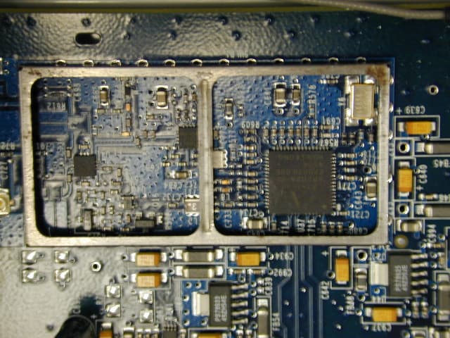
SN85883
Oct 20, 2005Wireless LAN modem
Equipment Class
DTS - Digital Transmission System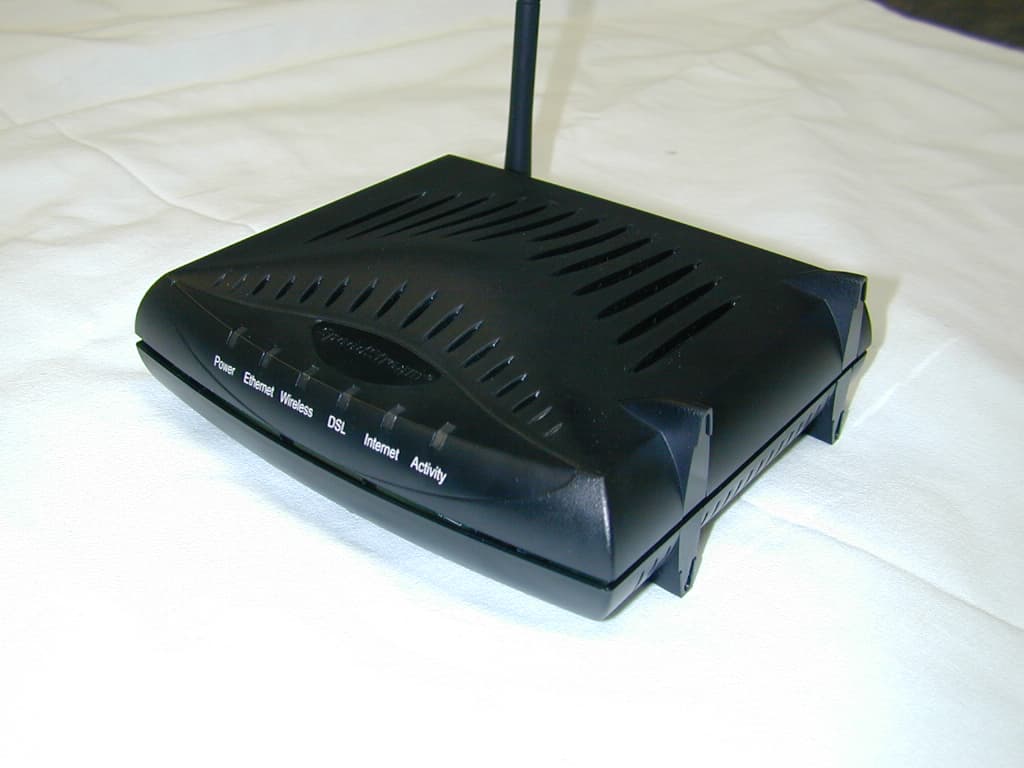
SN8N652
Aug 24, 2005Wireless DSL Modem
Equipment Class
DTS - Digital Transmission System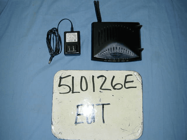
SN8R651
Jun 13, 2005802.11 b/g Wireless DSL Modem
Equipment Class
DTS - Digital Transmission System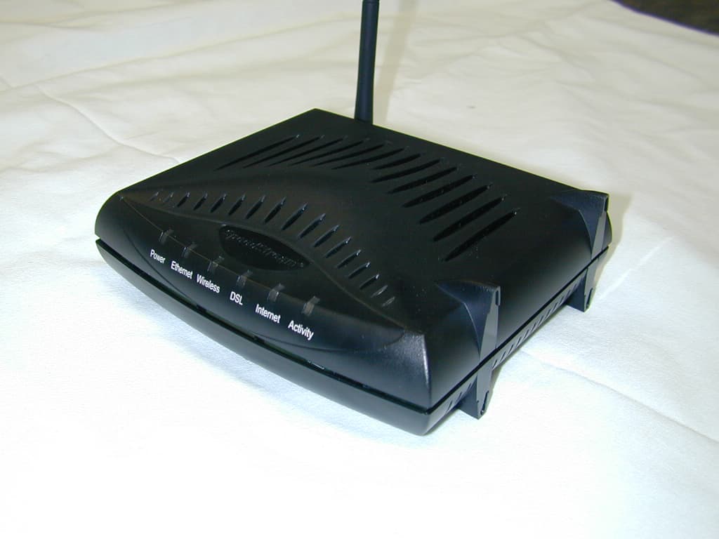
SN8N651
Jan 20, 2005Wireless DSL Modem
Equipment Class
DTS - Digital Transmission System