SNA-5125-5132REMOTE TRAINER
Woodstream Corporation
Click to zoom
Application Details
- Equipment Class
- DSC - Part 15 Security/Remote Control Transmitter
- Date of Grant
- Nov 04, 2004
- Application Purpose
- Original Equipment
- Date of Application
- Nov 04, 2004
- Equipment Note
- REMOTE TRAINER
- Frequency Range
- 303.62500000 - 304.02500000
- Company
- Woodstream Corporation
- Country
- United States
Documents & Files
Document Text
Text extracted from the exhibit documents filed with the FCC. Open a document above to read the original.
Block Diagram
+ 2.4V CLOCK 32.768 KHZ MATRIX SWITCH 1 1 of Sheet Filename Drawn by Date N/A Rev Model ScaleTitle 4321 AB CD 1234 D C B A WOODSTREAM BLOCK DIAGRAM 5125-5132 1-NOV-04 CHARGER CONVERTER CONTROLLER MSP430F1121 A TRANSMITTER CIRCUIT 303.825 MHZ AND REGULATOR 3.3 VOLTS
Operational Description
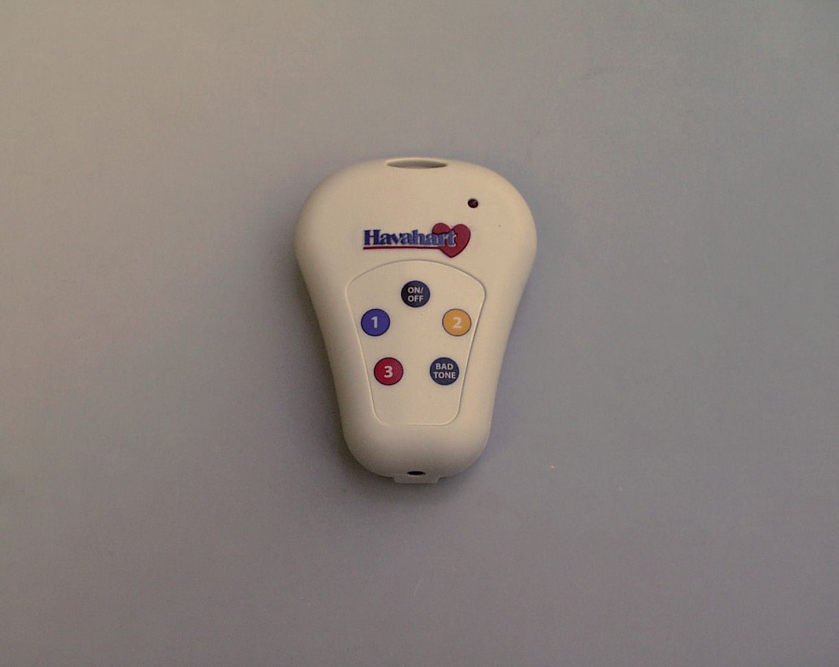
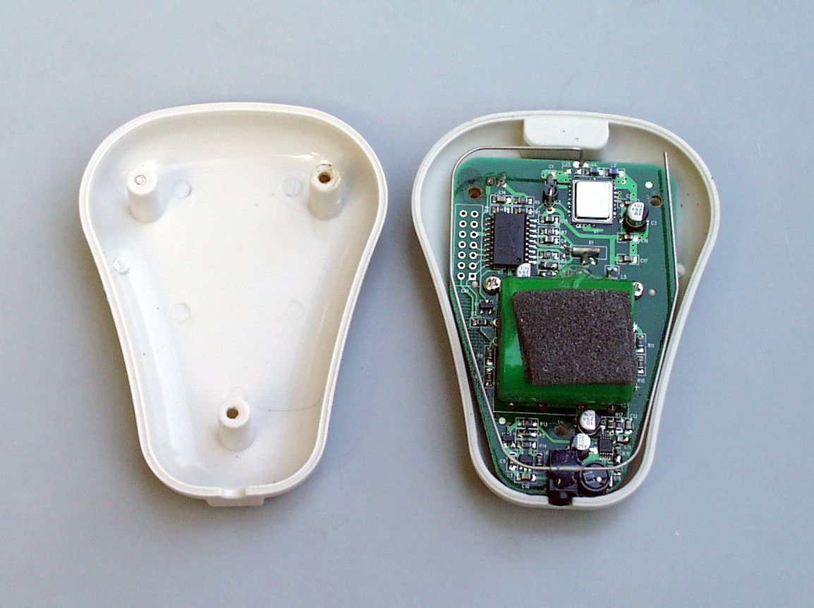
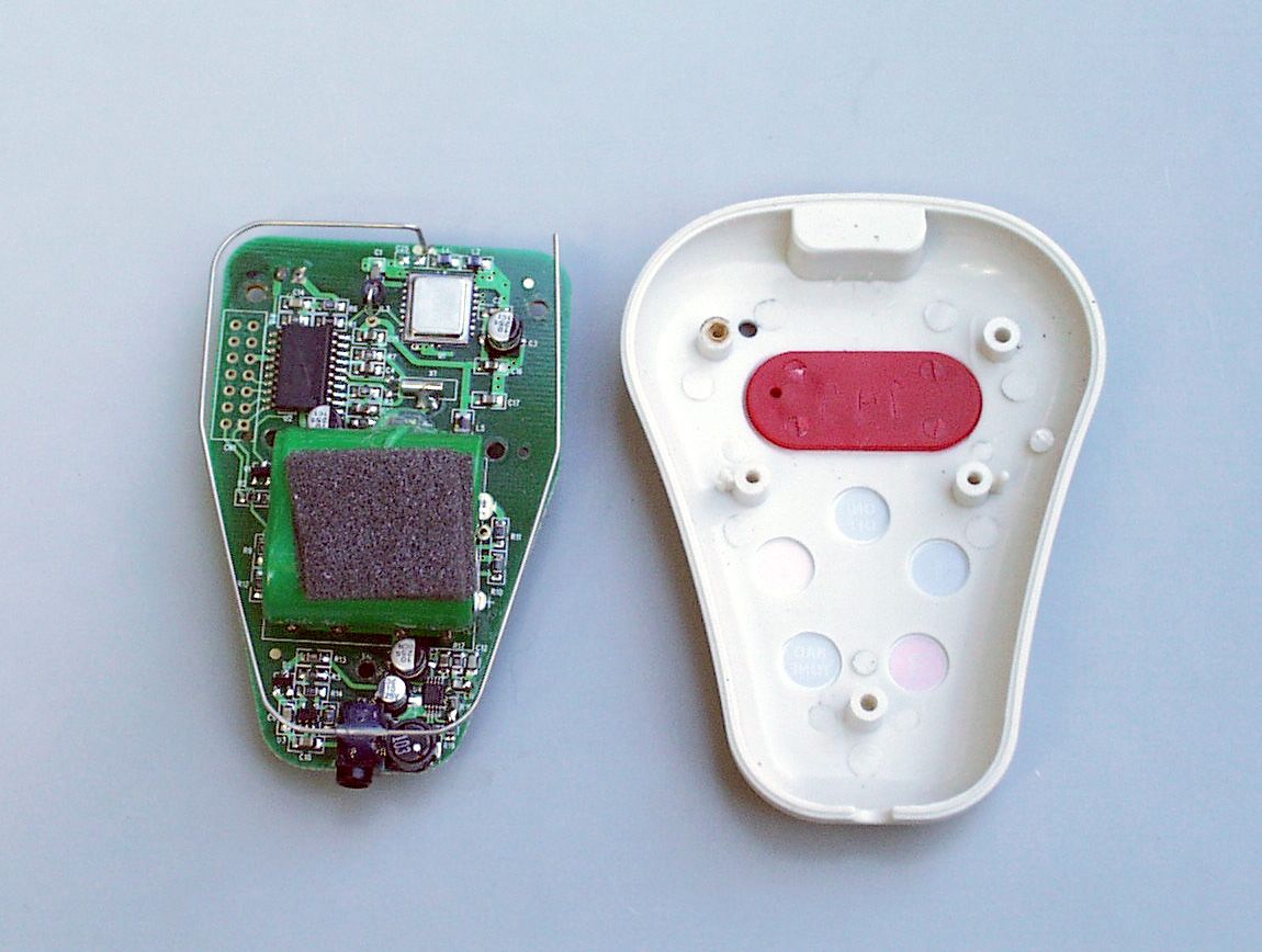
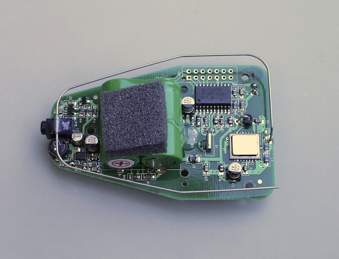
Remote Transmitter Circuit Operational Description U1 is an RFM TX5003 transmitter – the chip, in conjunction with the associated circuitry, is used in the on-off keyed (OOK) configuration. The RFM TX5003 operates at 303.825 MHz, the antenna is approximately 8.3 inches, a single strand wire. Q1 operates as a switch, completing a hard reset to U2; it also holds U2 in reset while the battery is being charged – this renders U2 inoperable when connected to the battery charger. U2 and its associated circuitry are the microprocessor control of the circuit – the mcu is controlled by user-activated switches. The mcu is synchronized to U1 (RF chip), and controls U1’s output. The clock oscillator for the mcu is 32.786kHz. JTAG connector ports are added for on-board programming. U3 and associated circuitry regulate the incoming voltage – incoming voltage from the wall mount battery charger is regulated down to 4.5Vdc. This circuitry controls the input voltage, and provides a trickle charge to the battery pack. U4 and its associated circuitry offer a boost converter to provide a Vcc higher than the 2.4Vdc of the battery pack. 11/4/2004 Larry L. Harman
Test Report
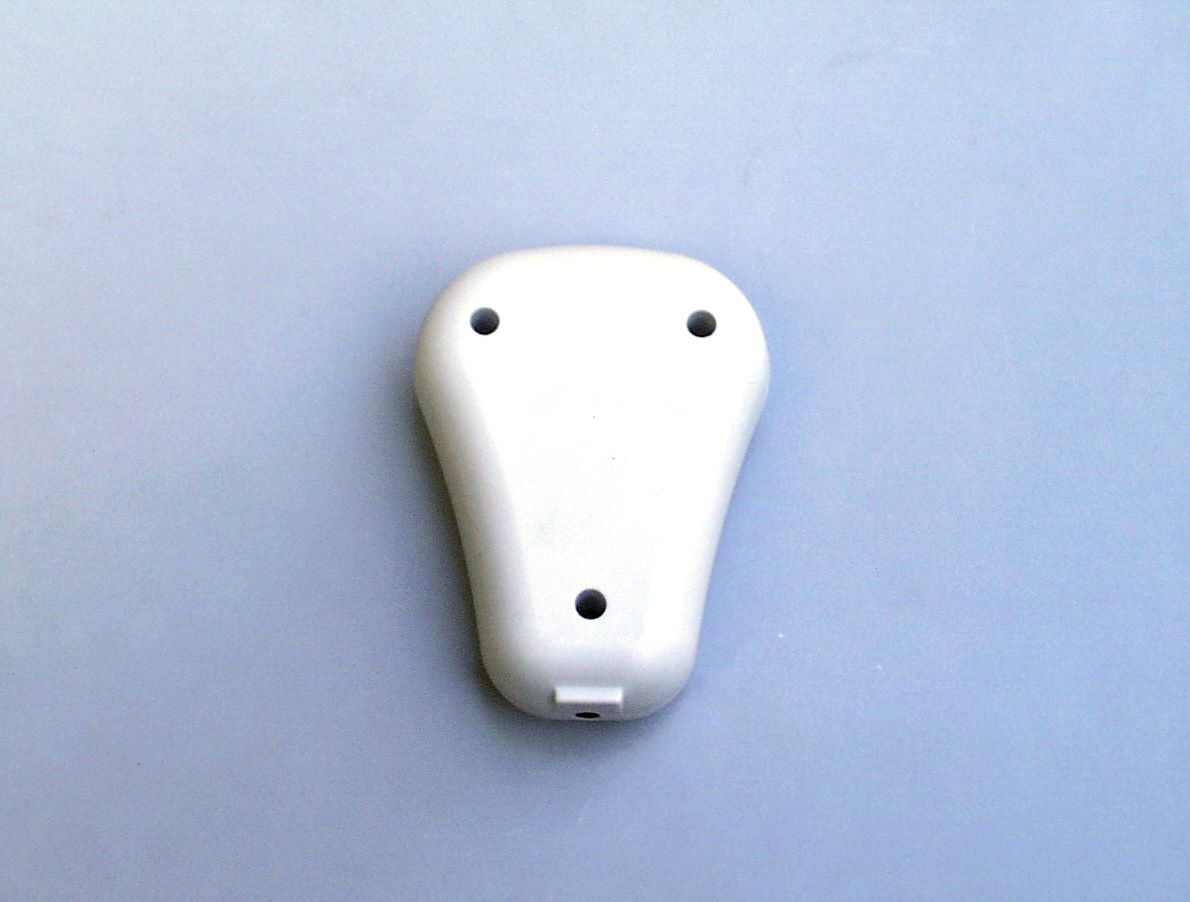
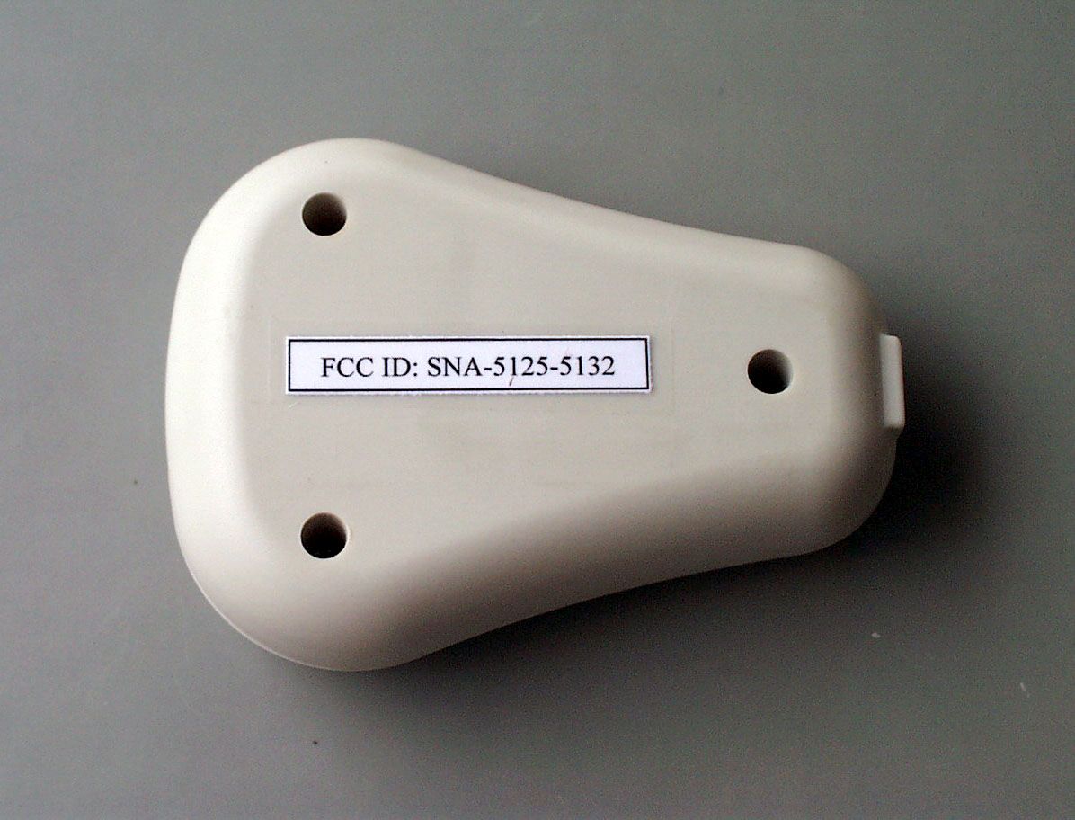
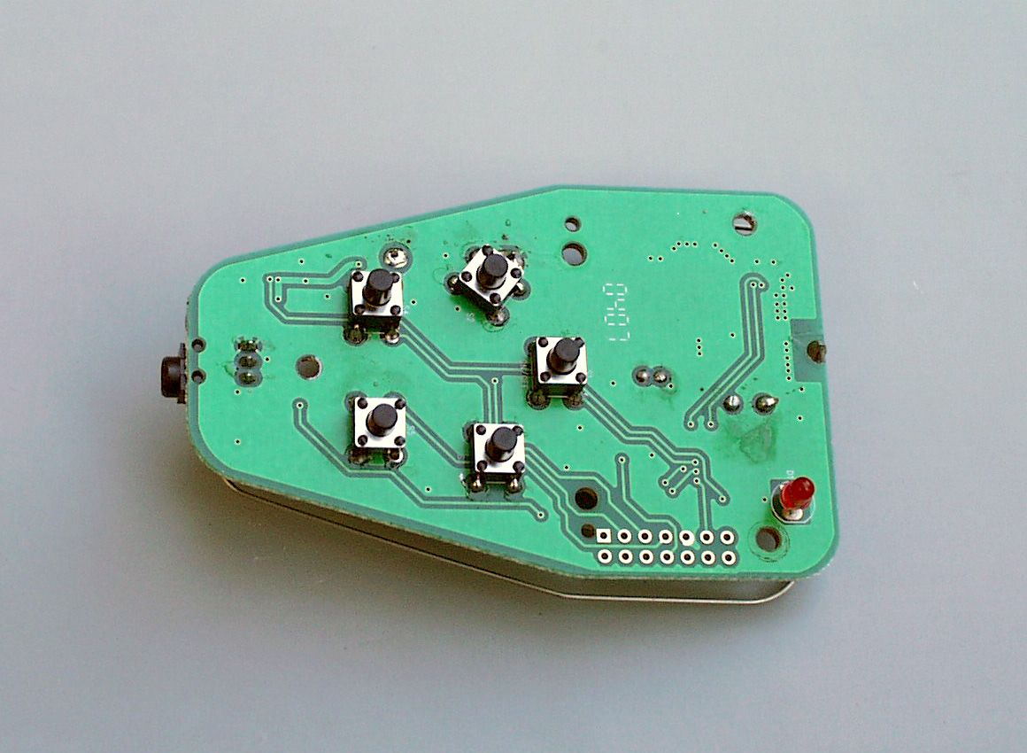
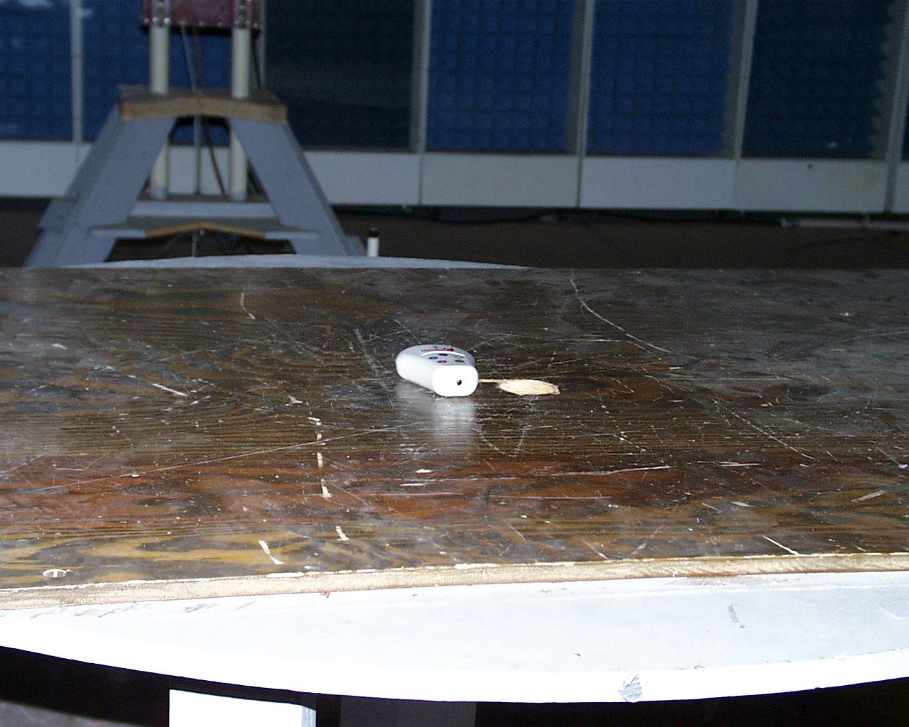
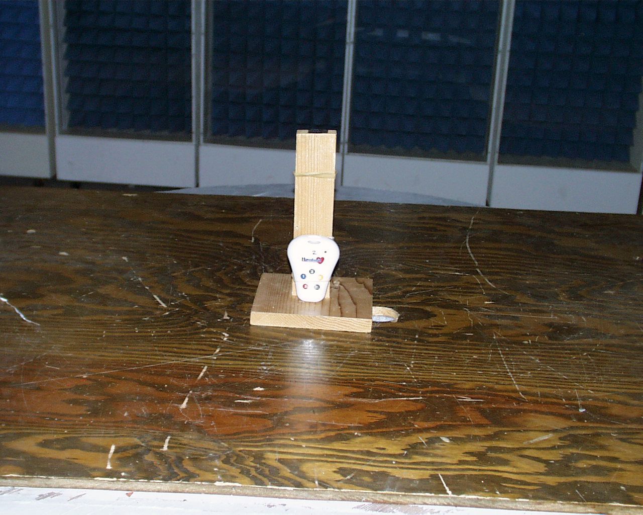
SNA-5125-5132 Woodstream Test Report of an Intentional Radiator for Certification under Part 15.231 of the FCC rules DUT: Remote Control Transmitter FCC ID SNA-5125-5132 Test Date: 21-October-2004 Manufacturer: Woodstream Corporation 69 North Locust St. Lititz, PA 17543 (717) 626-2125 Conducted at: Carl T. Jones site #90490 Springfield, VA Prepared by: Control Design & Testing, Inc. 6010 Red Fox Drive Spotsylvania, VA 22553 (540) 582-2826 1 SNA-5125-5132 Woodstream A. DEVICE UNDER TEST The device is a handheld, five button transmitter used to control the circuitry in a electronic dog collar as part of a remote training system. This product is designed to operate under the provisions of Part 15.231 of the FCC rules and RSS-210 in Canada. The frequency of operation is 303.825 MHz., nominal. The modulation mode is on/off pulse keying using binary code in Manchester format. The test samples were supplied in the final production plastic enclosure. The device is powered by an internal, rechargable battery pack and regulated at 3.3 volts DC. When the charging transformer is connected, the rf and controller circuits are disabled and the device cannot transmit. The transmitter circuit is comprised of an RF Monolitihics TR5003 hybrid IC, a two element inductive matching network and a formed steel wire antenna. The antenna is hard soldered to the circuit board. There is no provision to connect an external antenna. B. MEASUREMENT: RADIATED EMISSIONS Radiated emissions testing of this device was conducted at the Carl T. Jones test facility located in Springfield, Virginia. FCC Site #90490; IC Site #3101. The field strength measurements were conducted according to the procedures set forth in ANSI C63.4 (1992). The device under test was placed on a rotating turntable 0.8 meters high, centered at 3 meters distant from the measurement antenna. The device was placed in the center of the turntable and tested in the positions shown in the test setup photographs In normal operation, this device is programmed to transmit when any of the four control buttons is depressed and stops transmitting immediately when the button is released. However, transmission will cease automatically after ten seconds if the button is not released. For the purpose of radiated emissions testing, the test sample was specially programmed to continuously transmit its normal code sequence after pressing the “ON” button. The occupied bandwidth plot below (Plot 1) was captured using this signal. The occupied bandwidth limit for this frequency is 759.56 KHz. 2 SNA-5125-5132 Woodstream Plot 1 3 SNA-5125-5132 Woodstream The field strength measurements were taken using an HP8596E spectrum analyzer, an EMCO 3121C dipole set, an EMCO 3115 double ridge guide horn and an Avantek UJ210 preamp. The device was scanned from 30 MHz. to 4 GHz. and all emissions were noted. The only emissions detected were the primary operating frequency and those harmonically related to the fundamental transmit frequency. The micro-controller is clocked at 32 KHz. but no emissions related to the clock were evident. At each detected emission frequency, the device was measured by rotating the turntable and adjusting the antenna height over a range of 1 to 4 meters to obtain the maximum output level. This procedure was performed with both horizontal and vertical antenna polarizations for both of the positions shown in the test setup photos. The peak reading for each frequency was recorded in the fourth column in Table 1 below. Measurements taken for weak emissions were performed by reducing the distance from the measurement antenna to 1 meter and factoring –9.54dB into the calculation. This method was used for the 6 th and 7 th harmonics. CLIENT: WOODSTREAMFCC ID: SNA-5125-5132 DUT: HANDHELD TRANSMITTER PART 15.231(a)DATE: 21-OCT-04 Ant. Polar. H/V 303.875H20.1-42.8812.81625537245578 607.750H26.4-84.7112.827262578 911.625H30.7-90.5312.822852578 1215.500V29.2-91.7312.816738500 1519.375V31.0-95.0112.814132500 1823.250V32.2-92.2412.822351578 2127.125H33.8-102.6312.88119578 Table 1 RADIATED EMISSIONS DATA Frequency In MHz. Peak Power uV/m@3m Peak reading dBm Ant. Factor dB ANTENNA: DIPOLES/DRG HORN Duty Cycle -dB 15.231(a) Limit uV/m@3m Corrected Power uV/m@3m 4 SNA-5125-5132 Woodstream C. DUTY CYCLE AND INTERVAL CALCULATIONS The occupied bandwidth and duty cycle measurements were made using an HP8594E spectrum analyzer and plotted with an HP7475A pen plotter. The computation for the duty cycle correction factor for column five in Table 1 is derived from the manufacture’s description of the data scheme and is verified by plots 2 through 6. The data format for this device is standard 50% duty cycle Manchester phase consisting of a single 3.8ms. start bit followed by a 490μs. space, then thirty-eight, 980μs. bit frames. Each bit occupies half of the frame or, 490μs. The total on time for the data portion of one packet is 18.62ms. The packets are transmitted at 98.250ms. intervals so there are 1.018 packets in a 100ms time period. The net 100ms. duty cycle is calculated below. Start bit (3.8ms.) + Packet on time (18.62ms.) X 1.018 = Total on time (22.8235ms.) 20log (22.8235ms.)/100ms.) = -12.83 dB. As provided in Part 15.35 of the FCC rules, a correction factor of –12.8 dB is used for the calculations on the data sheet. The duty cycle corrected levels appear in the 7 th column in the table above. 5 SNA-5125-5132 Woodstream Plot 2 6 SNA-5125-5132 Woodstream Plot 3 7 SNA-5125-5132 Woodstream Plot 4 8 SNA-5125-5132 Woodstream Plot 5 9 SNA-5125-5132 Woodstream Plot 6 10
Contact Information
Applicant
Dwayne Arrighy
Test Firm
Carl T. Jones CorporationCarl Jones
Technical Specifications
| # | Rule Parts | Frequency Range | Power Output |
|---|---|---|---|
| 1 | 15.231 | 303.625 MHz - 304.025 MHz | - |
Other Applications from Woodstream Corporation
SNA-V430B
Apr 14, 2024V430B Rodent Snap Trap
Equipment Class
DTS - Digital Transmission System
SNA-V440
Dec 07, 2022Bait Box Rodent Trap with LoRa Radio
Equipment Class
DTS - Digital Transmission System
SNA-M2
May 10, 2020WiFi Rat Trap
Equipment Class
DTS - Digital Transmission System
SNA-M1
May 10, 2020WiFi Mousetrap
Equipment Class
DTS - Digital Transmission System
SNA-V400MR1
Mar 11, 2020LoRa Radio Connected Rodent Trap
Equipment Class
DTS - Digital Transmission System