SNBDM1000Dual Mode GSM850/1900 & 2.4 GHz FHSS Cordless Ph
Waxess Inc.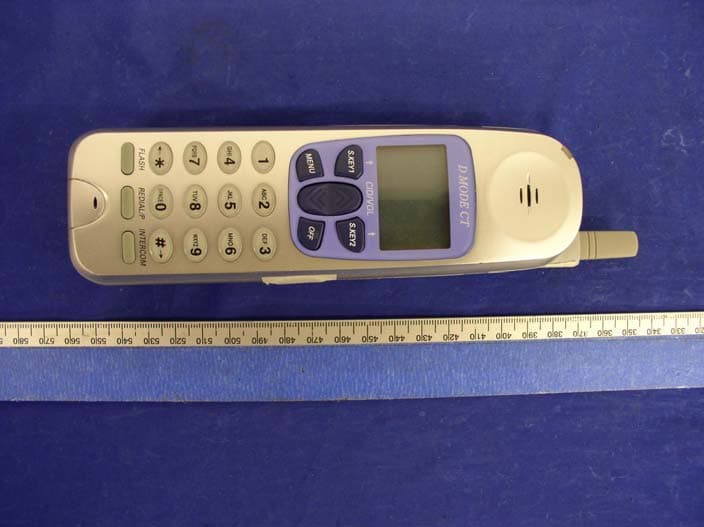
Click to zoom
Application Details
- Equipment Class
- DSS - Part 15 Spread Spectrum Transmitter
- Date of Grant
- Jan 17, 2005
- Application Purpose
- Original Equipment
- Date of Application
- Jan 17, 2005
- Equipment Note
- Dual Mode GSM850/1900 & 2.4 GHz FHSS Cordless Ph
- Frequency Range
- 2401.00000000 - 2482.00000000
- Company
- Waxess Inc.
- Country
- United States
Documents & Files
Document Text
Text extracted from the exhibit documents filed with the FCC. Open a document above to read the original.
Users Manual
D Mode CT User Guide FCC Draft D mode CT FCC DRAFTiiCopyright © 2004 Waxess Inside front cover fold-out Handset illustration Base unit illustration D Mode CT FCC DRAFTiiiCopyright © 2004 Waxess Front cover over-leaf • INTRODUCTION The D Mode CT is a very unique, all-in-one wireless (cellular) and PSTN (landline) communications device. This new product addresses the fast paced-convergence of wireless and cellular, as well as transitioning from landline usage to wireless service usage at home. This innovative product combines landline (in the home) phone service with cellular (mobile) phone service. With this one device, you can now make and receive phones calls at home using your traditional home phone service and/or your mobile wireless service. The competitive landscape of the cellular industry and driven down the cost of wireless service. Now, you can have that affordable pricing in your home. With its higher power, the new D Mode CT safely provides uninterrupted phone service in your home. No more dead spots. No more sporadic disconnects. You can roam freely around the house using a standard 2.4GHz cordless handset while utilizing your cellular service. • FEATURES • Interchangeable CDMA or GSM cellular modules • 2.4GHz DSS Multiple Handset Cordless Telephone • Caller ID from both Cellular and Land Line service • E-mail and SMS 3-Way Conference with Cellular and PSTN Lines • Conferencing with both Cellular and PSTN Lines • 1W or 850mA high power output Multiple Cordless Handsets (4 Maximum) • Corded Phone Handset on Base •Dual Keypad • Speakerphone •Large LCD on Base • Menu-Driven Operation • Power Backup Battery (option) • Voicemail Access (FSK/SDT VMWI for PSTN • Digital audio processing • 50 number caller ID memory • 50 Number phone book memory • Speed dial with keys 0 - 9 • 64-line, 16 digit backlit LCD on Handset and Base • 5 number redial memory with up to 32 digits each • Redial, flash • 14 day standby and 7 - 8 hour talk time • Tone/Pulse switchable • WEB SITE URL AND OTHER CONTACT INFORMATION D mode CT FCC DRAFTivCopyright © 2004 Waxess D Mode CT FCC DRAFTvCopyright © 2004 Waxess Contents Introduction . . . . . . . . . . . . . . . . . . . . . . . . . . . . . . . . . . . . . . iii Features . . . . . . . . . . . . . . . . . . . . . . . . . . . . . . . . . . . . . . . . . . iii Web site url and other contact information . . . . . . . . . . . . . . . . . . iii Get ready . . . . . . . . . . . . . . . . . . . . . . . . . . . . . . . . . . 1 Open . . . . . . . . . . . . . . . . . . . . . . . . . . . . . . . . . . . . . . . . . . . . 1 Prepare . . . . . . . . . . . . . . . . . . . . . . . . . . . . . . . . . . . . . . . . . . 1 Choose Location . . . . . . . . . . . . . . . . . . . . . . . . . . . . . . . . . . . . 1 Get set . . . . . . . . . . . . . . . . . . . . . . . . . . . . . . . . . . . . 4 Set the dialing mode . . . . . . . . . . . . . . . . . . . . . . . . . . . . . . . . . 4 Set the area code . . . . . . . . . . . . . . . . . . . . . . . . . . . . . . . . . . . 4 Set the language . . . . . . . . . . . . . . . . . . . . . . . . . . . . . . . . . . . . 4 Set time and date . . . . . . . . . . . . . . . . . . . . . . . . . . . . . . . . . . . 4 Set the ringer tone . . . . . . . . . . . . . . . . . . . . . . . . . . . . . . . . . . 4 Name the unit . . . . . . . . . . . . . . . . . . . . . . . . . . . . . . . . . . . . . . 5 Set up CID/CIDW . . . . . . . . . . . . . . . . . . . . . . . . . . . . . . . . . . . 6 Set up area code . . . . . . . . . . . . . . . . . . . . . . . . . . . . . . . . . . . . 6 Register handset . . . . . . . . . . . . . . . . . . . . . . . . . . . . . . . . . . . . 6 GO! . . . . . . . . . . . . . . . . . . . . . . . . . . . . . . . . . . . . . . 7 Make a CEL call . . . . . . . . . . . . . . . . . . . . . . . . . . . . . . . . . . . . . 7 Make a TEL call . . . . . . . . . . . . . . . . . . . . . . . . . . . . . . . . . . . . . 7 Answer a CEL call . . . . . . . . . . . . . . . . . . . . . . . . . . . . . . . . . . . 7 Answer a TEL call . . . . . . . . . . . . . . . . . . . . . . . . . . . . . . . . . . . 7 Phone book . . . . . . . . . . . . . . . . . . . . . . . . . . . . . . . . . . . . . . . 8 Messages . . . . . . . . . . . . . . . . . . . . . . . . . . . . . . . . . . . . . . . . . 9 Precautions . . . . . . . . . . . . . . . . . . . . . . . . . . . . . . . 11 Important Safety Instructions . . . . . . . . . . . . . . . . . . . . . . . . . . 11 I.C. Notice . . . . . . . . . . . . . . . . . . . . . . . . . . . . . . . . . . . . . . . 17 General information . . . . . . . . . . . . . . . . . . . . . . . . . . 18 D modeviCopyright © 2004 Waxess D Mode CT FCC DRAFT1Copyright © 2004 Waxess 1Get ready •OPEN List of included items Base unit Handset SIM card Accessories • PREPARE About the SIM card This phone connects to GSM networks through a Subscriber Identity Module card. The SIM card carries information about your wireless account. Here are some important considerations: • Keep all SIM cards out of the reach of small children. • The SIM card and its contacts are easily damaged by scratches or bending, so be careful when handling, inserting, or removing the card. • Always make sure to disconnect power from the phone before removing or inserting the SIM card. Install the SIM card 1 Verify that power is disconnected from the phone. 2 Open the SIM card cover (??) 3 Align the SIM card with the beveled corner facing (??), gold contact area facing downward (??) 4 Carefully insert the SIM card. • CHOOSE LOCATION Before choosing a location for your new phone, read “Installation Considerations” in the Precautions and Warranty section. Some important considerations: • Charge the handset for 12 - 15 hours before using. • The location should be close to both a phone jack and a power outlet which is not switchable. • Keep the base and handset away from sources of electrical noise such as motors and fluorescent lighting. • Leave enough room to raise both base antennas fully vert…
Text truncated - open the document above for the full version.
Cover Letter(s)
――――――――――――――――――――――――――――――――――――――――――――― Waxess, Inc. 34 Executive Park, Suite 250, Irvine, CA 92614 Tel: (949) 955-9542; Fax: (949) 955-2470 November 12, 2004 Federal Communications Commission Authorization and Evaluation Division Confidentiality Request regarding application for certification of FCC ID:_SNBDM1000 Pursuant to Sections 0.457 and 0.459 of the Commission’s Rules, we hereby request confidential treatment of information accompanying this application as outlined below: Parts List Schematics Tune-up Procedure Operational Description Block Diagrams The above materials contain trade secrets and proprietary information not customarily released to the public. The public disclosure of these materials may be harmful to the applicant and provide unjustified benefits to its competitors. The applicant understands that pursuant to Section 0.457 of the Rules, disclosure of this application and all accompanying documentation will not be made before the date of the Grant for this application. Sincerely, Hideyuki Kanakubo COO
External Photos
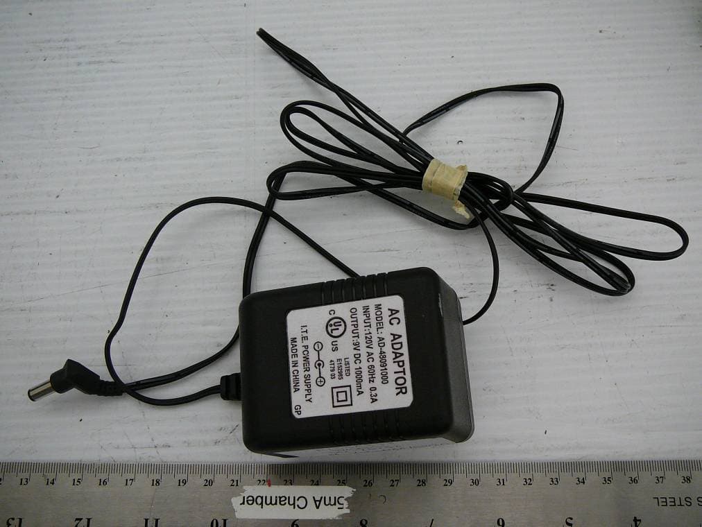
EXHIBIT C - EUT EXTERNAL PHOTOGRAPHS Base Top View Base Bottom View Handset Top View Handset Bottom View Adapter for Base Adapter for Charger Charger
ID Label/Location Info
XHIBIT A - FCC ID LABEL INFORMATION Proposed FCC ID Label Specifications: Text is black or white in color and is left justified. Labels are silk- screened and shall be “permanently affixed” at a conspicuous location on the EUT. Proposed Label Location on EUT Rear View of EUT/FCC ID Label FCC ID: SNBDM1000 This device complies with Part 15 of the FCC Rules. Operation is subject to the following two conditions: (1) this device may not cause harmful interference, and (2) this device must accept any interference received, including interference that may cause undesired operation. Privacy of communication may not be ensured when using this phone FCC ID: SNBDM1000
Internal Photos
EXHIBIT C - EUT INTERNAL PHOTOGRAPHS Dmode PCB Base Top Dmode PCB Base Bottom Base PCB Top View Base PCB Bottom View Dmode PCB HS front Dmode PCB HS Back Handset Cover off View
RF Exposure Info
RF EXPOSURE SAR evaluation for handset. Per the formula (60 / fGHz ) mW, d < 2.5 cm, the threshold is 60 / 2.441 = 24.6 (mW) Per the formula P = A + G + 10 log (1/x) , P : Peak eirp (dBm) A : Conducted average power (dBm) G : Antenna gain (dBi) x : Duty cycle = TXon / (TXon + TXoff ), So, conducted average power A = P - G - 10 log (1/x) , For the EUT : P = conducted peak power16.3dBm + antenna gain 0dBi = 16.3dBm, G = 0dBi , x = 0.0008 . So, A = 16.3 - 0 - 10 log (1/ 0.0008) = -14.6 (dBm) = 0.035 (mW) So, A = 0.035 mW < 24.6 mW Because the antenna gain (typical) is 0 dBi, so the average eirp is the same value as A = 0.035 mW < 24.6 mW. No SAR test is required for this EUT.
RF Exposure Info
§15.247 (b)(4) - RF EXPOSURE According to §15.247(b)(4) and §1.1307(b)(1), systems operating under the provisions of this section shall be operated in a manner that ensures that the public is not exposed to radio frequency energy level in excess of the Commission’s guidelines. According to §1.1310 and §2.1093 RF exposure is calculated. Limits for Maximum Permissive Exposure (MPE) Frequency Range (MHz) Electric Field Strength (V/m) Magnetic Field Strength (A/m) Power Density (mW/cm 2 ) Averaging Time (minute) Limits for General Population/Uncontrolled Exposure 0.3-1.34 614 1.63 *(100) 30 1.34-30 824/f 2.19/f *(180/f 2 ) 30 30-300 27.5 0.073 0.2 30 300-1500 / / f/1500 30 1500-15000 / / 1.0 30 f = frequency in MHz * = Plane-wave equivalent power density MPE Prediction Predication of MPE limit at a given distance Equation from page 18 of OET Bulletin 65, Edition 97-01 S = PG/4πR² Where: S = power density P = power input to antenna G = power gain of the antenna in the direction of interest relative to an isotropic radiator R = distance to the center of radiation of the antenna Base: Maximum peak output power at antenna input terminal: 23.1 (dBm ) Maximum peak output power at antenna input terminal: 204.2 (mW) Prediction distance: 20 (cm) Predication frequency: 2400 (MHz) Antenna Gain (typical): 0 (dBi) Maximum antenna gain: 1(numeric) Power density at predication frequency at 20 cm: 0.04(mW/cm^2) MPE limit for uncontrolled exposure at prediction frequency: 1 (mW/cm^2) Test Result Base Unit: The predicted power density level at 20 cm is 0.04 mW/cm^2. This is below the uncontrolled exposure limit of 1mW/cm^2 at 2400 MHz. The EUT is used at least 20cm away from user’s body. It is determined as mobile equipment.
Test Report
Note: This test report is specially limited to the above client company and product model only. It may not be duplicated without prior written consent of Bay Area Compliance Laboratory Corporation. This report must not be used by the client to claim product endorsement by NVLAP or any agency of the U.S. Government. FCC Type Approval EMI MEASUREMENT AND TEST REPORT For Waxess Inc. 34 Executive Park, Suite 250 Irvine, CA 92614 FCC ID: SNBDM1000 This Report Concerns: Original Report Equipment Type: Transceiver, Dual Mode GSM850/1900 & 2.4GHz FHSS Cordless Phone Test Engineer: Ming Jin / Report No.: R0410203 Report Date: 2004-11-09 Reviewed By: Daniel Deng / Prepared By: Bay Area Compliance Laboratory Corporation (BACL) 230 Commercial Street Sunnyvale, CA 94085 Tel: (408) 732-9162 Fax: (408) 732 9164 Waxess Inc. FCC ID: SNBDM1000 Report # R0410203Rpt-a.doc Page 2 of 74 FCC Type Approval Report TABLE OF CONTENTS GENERAL INFORMATION.......................................................................................................................................5 PRODUCT DESCRIPTION FOR EQUIPMENT UNDER TEST (EUT) ....................................................................................5 OBJECTIVE...................................................................................................................................................................5 RELATED SUBMITTAL(S)/GRANT(S).............................................................................................................................5 TEST METHODOLOGY..................................................................................................................................................6 TEST FACILITY.............................................................................................................................................................6 SYSTEM TEST CONFIGURATION ..........................................................................................................................7 JUSTIFICATION.............................................................................................................................................................7 BLOCK DIAGRAM.........................................................................................................................................................7 EQUIPMENT MODIFICATIONS.......................................................................................................................................7 LOCAL SUPPORT EQUIPMENT LIST AND DETAILS........................................................................................................7 REMOTE SUPPORT EQUIPMENT LIST AND DETAILS......................................................................................................7 POWER SUPPLY INFORMATION.....................................................................................................................................7 CONFIGURATION OF TEST SYSTEM..............................................................................................................................8 TEST SETUP BLOCK DIAGRAM.....................................................................................................................................8 SUMMARY OF TEST RESULTS FOR FCC PART 15............................................................................................9 ANTENNA REQUIREMENT ....................................................................................................................................10 §15.207(A) - CONDUCTED EMISSION...................................................................................................................11 MEASUREMENT UNCERTAINTY..................................................................................................................................11 TEST SETUP................................................................................................................................................................11 SPECTRUM ANALYZER SETUP....................................................................................................................................11 TEST EQUIPMENT LIST AND DETAILS.........................................................................................................................11 TEST PROCEDURE......................................................................................................................................................11 ENVIRONMENTAL CONDITIONS..................................................................................................................................12 SUMMARY OF TEST RESULTS.....................................................................................................................................12 CONDUCTED EMISSIONS TEST DATA.........................................................................................................................12 PLOT OF CONDUCTED EMISSIONS TEST DATA...........................................................................................................12 §15.205 & §15.209 - RADIATED EMISSION...........................................................................................................15 MEASUREMENT UNCERTAINTY..................................................................................................................................15 TEST SETUP................................................................................................................................................................15 SPECTRUM ANALYZER SETUP....................................................................................................................................15 TEST EQUIPMENT LIST AND DETAILS.........................................................................................................................15 ENVIRONMENTAL CONDITIONS..............................…
Text truncated - open the document above for the full version.
Test Setup Photos
EXHIBIT B - TEST SETUP PHOTOGRAPHS Conducted Emission – Front View Conducted Emission- Side View Base Radiated Emission – Front View (2.4GHz FHSS) Base Radiated Emission – Rear View (2.4GHz FHSS) Base Radiated Emission – Front View (GSM) Base Radiated Emission – Rear View (GSM) Handset Radiated Emission – Front View (2.4GHz FHSS) Handset Radiated Emission – Rear View (2.4GHz FHSS)
Contact Information
Applicant
Hidekazu Nakama
Test Firm
Bay Area Compliance LaboratoryJohn Chan
Technical Specifications
| # | Rule Parts | Frequency Range | Power Output |
|---|---|---|---|
| 1 | 15C | 2.40 GHz - 2.48 GHz | 204.00 mW |
Other Applications from Waxess Inc.
SNBDM1000CE
Oct 14, 2010Home Cellular Cordless Telephone
Equipment Class
PCB - PCS Licensed Transmitter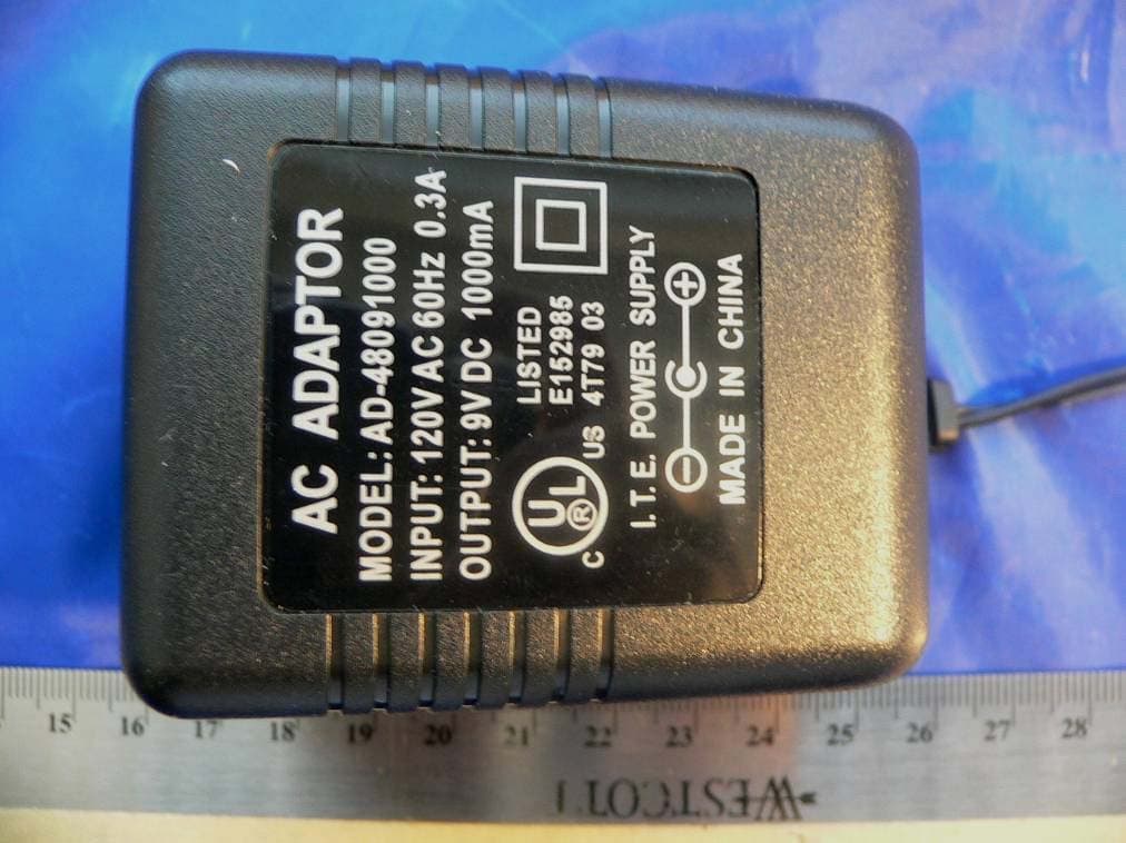
SNBDM1200E
Jan 17, 20072.4 GHz FHSS cordless phone
Equipment Class
DSS - Part 15 Spread Spectrum Transmitter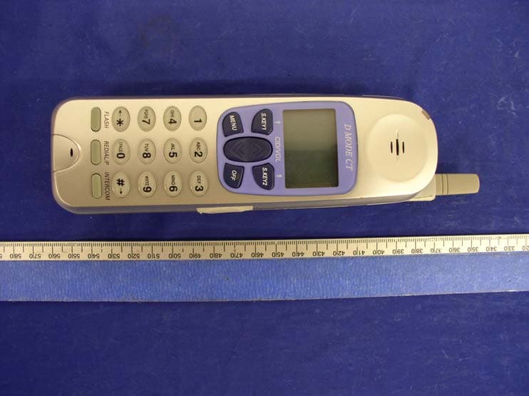
SNBDM100HS
Apr 20, 2005Dual Mode CDMA 850/1900 MHz & 2.4GHz FHSS Phone
Equipment Class
DSS - Part 15 Spread Spectrum Transmitter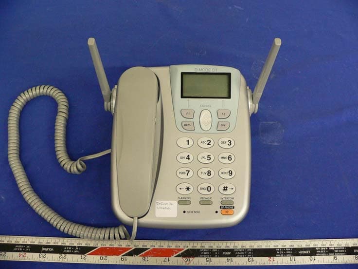
SNBDM1000C
Apr 04, 2005Dual Mode CDMA 850/1900 MHz & 2.4GHz FHSS Phone
Equipment Class
DSS - Part 15 Spread Spectrum Transmitter