SNL-16003510Receiver GR-12L Graupner/SJ HoTT
GRAUPNER CO., LTD.
Click to zoom
Application Details
- Equipment Class
- DSS - Part 15 Spread Spectrum Transmitter
- Date of Grant
- Jun 09, 2013
- Application Purpose
- Original Equipment
- Date of Application
- Jun 09, 2013
- Equipment Note
- Receiver GR-12L Graupner/SJ HoTT
- Frequency Range
- 2404.05600000 - 2474.02500000
- Company
- GRAUPNER CO., LTD.
- Country
- South Korea
Documents & Files
Document Text
Text extracted from the exhibit documents filed with the FCC. Open a document above to read the original.
Users Manual
GR-12L 6 Channel HoTT 2.4GHz Receiver OPERATING INSTRUCTION Optimized Digital Proportional System Prior to use, please read this manual thoroughly. Keep this manual in a convenient place for quick and easy reference. BEFORE USE Thank you for purchasing 6CH HoTT 2.4GHz receiver. This system is extremely versatile and may be used by beginners and pros alike. In order for you to make the best use of your system and to fly safely, please read this manual carefully. If you have any difficulties while using your system, please consult the manual, our online Frequently Asked Questions (on the web pages referenced below), your hobby dealer, or the SJ Service Center. Due to unforeseen changes in production procedures, the information contained in this manual is subject to change without notice. SUPPORT AND SERVICE • Customer support Please feel free to ask any question by e-mail or phone. We‟ve been trying to deal with your question. We are open from nine to six, Monday to Friday in Korea. We may respond to your question by e-mail as soon as possible when we are close. • Internet sales site Please feel free to contact “www.openhobbby.com” to stay up to date the latest SJ Firmware and the newest product line up • A/S regulation Only when the product is faulty after normal operation within the warranty period, we will repair the product for free based on our regulations. The repair will be paid for by the consumer when the damage is due to use in improper ways or beyond the warranty period. • Warranty regulation Refer the WARRANTY CARD in a Package OPENHOBBY A/S CENTER 202 Dong- 201, Chunui Techno-Park II, 18, 198 street, Bucheon-ro, Wonmi-Gu, Bucheon-Shi, Gyungki-Do KOREA 420-857 Phone: 82-70-7863-3674 Fax: 82-70-7863-3670 Customer Service E-mail: [email protected] INTRODUCTION SJ GR-12L/ GR-12Li/ GR-12Lm HoTT receivers are compatible with SJ T series transmitter and used to airplane, helicopter and glider. HoTT system gives user real-time information on various useful data such as user model‟s RPM, voltage, temperature, user programmable warning, and so on which are directly obtained from telemetric speed controllers equipped with this HoTT system without having to install separate sensor devices. Of course, all of those telemetric data can be also transmitted from separate sensor devices. The use of up to 75 hopping channels provides advanced reliable operation while keeping from any external interference. All instructions, warranties and other collateral documents are subject to change at the sole discretion of SJ INCORPORATED. For up-to-date product literature, visit http://www.openhobby.com and click on the support tab for this product WARNING: Read the ENTIRE instruction manual to become familiar with the features of the product before operating. Failure to operate the product correctly can result in damage to the product, personal property and cause serious injury. FLYING SAFETY • Do not fly your model near spectators, parking areas or any other area that could result in injury to people or damage of property. • Ensure that all channels are working in the proper manner. • Perform a ground range check prior to the initial flight of the day • Do not fly during adverse weather conditions. Poor visibility can cause disorientation and loss of control of your aircraft. Strong winds can cause similar problems • We strongly recommend to set the Failsafe function and also recommend that the preset Failsafe would be idle position • You need to set the function of the transmitter after removing a power battery from a model or stopping a engine of a model. • Ensure that all your batteries have been properly charged prior to flight. GENERAL INFORMATION 1. Products • GR-12L : Normal Rx 6ch 2. Features • The use of up to 75 channels ensures extreme operating reliability and immunity to external interference. • High bright LED allows to check the operating status • The optimized sizes and weights • Receiver input sensitivity and thus the range have been increased further. • Servo connections in the front panel. • Failsafe, Hold, OFF, and standard (channel 1 failsafe; all others hold) programmable. 3. The Specification When turning on or adjusting the radio control system it is essential to keep transmitter antenna at least 30 cm away from receiver antenna all the time. If transmitter antenna is too close to receiver antenna, receiver will be overloaded and the red status LED on receiver blinks red. Transmitter responds by repeating a single beep every second and the radio control system is entered Fail-Safe mode. If the distance of the antennas between transmitter and receiver would be simply longer than 30cm in this situation, the beep of transmitter is ceased and the red status LED on the receiver turns off 4. LED indicator You may check the signal reception according to status LED • LED off : Very good reception • LED blinking : Poor reception • LED on : No signal reception OPERATION 1. Binding • GR-12L Turn on receiver‟s power and press Bind button on receiver for 3 seconds, the red status LED turns off. Follow the procedures of your specific transmitter to bind, the system will connect within a few seconds. NOTICE: Once transmitter and receiver are connected, the red status LED on the receiver is off, indicating the receiver is bound to the transmitter. If the binding process has failed, repeat the whole procedure. • Binding a number of receivers in one model It is possible to bind a number of receivers to a transmitter in one model. Every receiver must be bound to the transmitter individually according to the procedure already described. The last bound receiver is the master receiver when the system is in use. Every telemetry sensors installed in the model must be connected to the master receiver, since the only master receiver transmits the sensor data through the downlink channel. The second and all further receivers are operated as the slave mode which are connected in parallel to the master …
Text truncated - open the document above for the full version.
Cover Letter(s)
SJ Incorporated SNL -16003510 Bucheon-Shi, Kyungki-Do , South Korea
Cover Letter(s)
SJ Incorporated Bucheon-Shi, Kyungki-Do, South Korea
External Photos
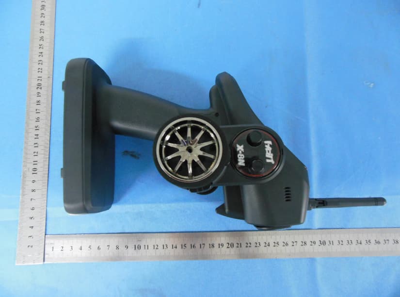
External Photographs EUT –Front View EUT – Rear View Antenna Location EUT – Side View
Internal Photos
Internal Photographs EUT - Open View EUT - PCB View EUT - PCB View
RF Exposure Info
Radio Frequency Exposure Report On Behalf of SJ Incorporated FCC ID: SNL-16003510 Product Description: Receiver GR-12L Graupner/SJ HoTT Model No.: GR-12L Supplementary Model: GR-12S,GR-12 Prepared for: SJ Incorporated 8th F,202 Dong,Chunui Techno-Park2,202,Chuni-Dong,Wonmi- Gu,Bucheon-Shi,Kyungki-Do,South Korea Prepared by: Bontek Compliance Testing Laboratory Ltd 1/F, Block East H-3, OCT Eastern Ind. Zone, Qiaocheng East Road, Nanshan, Shenzhen, China Tel: 86-755-86337020 Fax: 86-755-86337028 Report No.: BCT13DR121E-1 Issue Date: June 4, 2013 Test Date: April 18~ June 3, 2013 Tested by: Reviewed by: Lion Cai Kendy Wang Approved by: Tony Wu Report No.: BCT13DR121E-1 Page 2 of 5 TABLE OF CONTENTS 1 - GENERAL INFORMATION ....................................................................................................................... 3 1.1 PRODUCT DESCRIPTION FOR EQUIPMENT UNDER TEST (EUT) ........................................................................................ 3 1.2 OBJECTIVE ................................................................................................................................................................. 3 1.3 GENERAL DESCRIPTION OF TEST .................................................................................................................................. 4 1.4 HUMAN EXPOSURE ASSESSMENT RESULTS ................................................................................................................... 4 Report No.: BCT13DR121E-1 Page 3 of 5 1 - GENERAL INFORMATION 1.1 Product Description for Equipment Under Test (EUT) Applicant: SJ Incorporated Address of Applicant: 8th F,202 Dong,Chunui Techno-Park2,202,Chuni-Dong,Wonmi- Gu,Bucheon-Shi,Kyungki-Do,South Korea Manufacturer 1: SJ Technology(Shenzhen)Co.,Ltd Address of manufacturer: F6, 1 Bldg, A Area, Yintianxifa Industrial Area, Xixiang Town, Baoan District Shenzhen, Guangdong Province, China Manufacturer 2: SJ Incorporated Address of Manufacturer: 8th F,202 Dong,Chunui Techno-Park2,202,Chuni-Dong,Wonmi- Gu,Bucheon-Shi,Kyungki-Do,South Korea General Description of E.U.T Items Description EUT Description: Receiver GR-12L Graupner/SJ HoTT Model No.: GR-12L Trade Name: GRAUPNER/SJ HoTT Supplementary Model: GR-12S,GR-12 Frequency Band: 2404.056 MHz ~ 2474.025 MHz Channel Spacing: 1 MHz Number of Channels: 70 Type of Modulation: FHSS Antenna Gain: 1.5dBi Antenna Type: External Antenna Rated Voltage: Intput: DC 6V from battery Adapter description: Model: N/A Input: N/A Output: N/A Remark: * The test data gathered are from the production sample provided by the manufacturer. Supplementary Models are no difference. Management, according to the sales region. 1.2 Objective The objective of the following report is used to demonstrate that EUT operated in a manner that ensures the public is not exposed to radio frequency energy levels in excess of the relative provisions of FCC 47CFR Part 1.1307 Report No.: BCT13DR121E-1 Page 4 of 5 1.3 General Description of Test Items Description EUT Frequency band FHSS: 2.400GHz ~ 2.483GHz WLAN: 2.400GHz ~ 2.483GHz WLAN: 5.18GHz ~ 5.32GHz / 5.50GHz ~ 5.70GHz WLAN: 5.745GHz ~ 5825GHz Others: __________________________ Device category Portable (<20cm separation) Mobile (>20cm separation) Others __________________________ Exposure classification Occupational/Controlled exposure (S = 5mW/cm2) General Population/Uncontrolled exposure (S=1mW/cm 2 ) Others: __________________________ Antenna diversity Single antenna Multiple antennas: Tx diversity Rx diversity Tx/Rx diversity Max. output power 19.89dBm (0.0975W) Antenna gain (Max) 0 dBi (Numeric gain:1) Evaluation applied MPE Evaluation SAR Evaluation Note: 1. The maximum output power is 17.61dBm (0.05767W) at 2404.056MHz (with 1.42 numeric antenna gain.) 2. For mobile or fixed location transmitters, no SAR consideration applied. The minimum separation generally be used is at least 20 cm, even if the calculations indicate that the MPE distance would be lesser. 1.4 Human Exposure Assessment Results Report No.: BCT13DR121E-1 Page 5 of 5 EUT parameter (data from the separate report) Given Where G: numerical gain of transmitting antenna; TP: Transmitted power in watt; d: distance from the transmitting antenna in meter Max average output power in Watt (TP) 17.61dBm (0.05767W) Antenna gain (G) 1.5 dBi (Numeric gain: 1.42) Exposure classification S=1mW/cm 2 Minimum distance in meter (d) (from transmitting structure to the human body) 20cm (0.2m) Yields 2 30 3770 xPxG S d = , P=0.05767W, G=1.42, d=0.2 S=0.0163mW/cm 2 Or 30xPxG d= 3770S , S=1, P=0.05767W, G=1.42 d=0.026m Conclusion: S=0.0163mW/cm 2 is significant lower than the General Population Exposure Power Density Limit 1mW/cm 2 or except the distance when human body proximity to the antenna is less than 2.6cm then will reach the General Population Exposure Power Density Limit (For mobile or fixed location transmitters, the maximum power density is 1.0 mW / cm 2 even if the calculation indicates that the power density would be larger.)
Test Report
Test Report of FCC CFR 47 Part 15 Subpart C On Behalf of SJ Incorporated FCC ID: SNL-16003510 Product Description: Receiver GR-12L Graupner/SJ HoTT Model No.: GR-12L Supplementary Model: GR-12S,GR-12 Prepared for: SJ Incorporated 8th F,202 Dong,Chunui Techno-Park2,202,Chuni-Dong,Wonmi- Gu,Bucheon-Shi,Kyungki-Do,South Korea Prepared by: Bontek Compliance Testing Laboratory Co., Ltd 1/F, Block East H-3, OCT Eastern Ind. Zone, Qiaocheng East Road, Nanshan, Shenzhen, China Tel: 86-755-86337020 Fax: 86-755-86337028 Report No.: BCT13DR121E Issue Date: June 4, 2013 Test Date: April 18~ June 3, 2013 Tested by: Reviewed by: Lion Cai Kendy Wang Approved by: Tony Wu Report No.: BCT13DR121E Page 2 of 43 FCC ID: SNL-16003510 TABLE OF CONTENTS 1. GENERAL INFORMATION .................................................................................................................................... 4 1.1 PRODUCT DESCRIPTION FOR EQUIPMENT UNDER TEST (EUT) ......................................................................... 4 1.2 RELATED SUBMITTAL(S) / GRANT (S) AND TEST METHODOLOGY ....................................................................... 4 1.3 TEST FACILITY ...................................................................................................................................................... 5 2. SYSTEM TEST CONFIGURATION ...................................................................................................................... 6 2.1 EUT CONFIGURATION .......................................................................................................................................... 6 2.2 EUT EXERCISE ..................................................................................................................................................... 6 2.3 GENERAL TEST PROCEDURES ............................................................................................................................. 6 2.4 MEASUREMENT UNCERTAINTY ............................................................................................................................. 6 2.5TEST EQUIPMENT LIST AND DETAILS .................................................................................................................... 7 3. SUMMARY OF TEST RESULTS .......................................................................................................................... 8 4. TEST OF AC POWER LINE CONDUCTED EMISSION.................................................................................... 9 4.1 APPLICABLE STANDARD ....................................................................................................................................... 9 4.2 TEST SETUP DIAGRAM ......................................................................................................................................... 9 4.3 TEST RESULT ....................................................................................................................................................... 9 5. TEST OF HOPPING CHANNEL BANDWIDTH ................................................................................................ 10 5.1 APPLICABLE STANDARD ..................................................................................................................................... 10 5.2 EUT SETUP ........................................................................................................................................................ 10 5.3 TEST EQUIPMENT LIST AND DETAILS ................................................................................................................. 10 5.4 TEST PROCEDURE .............................................................................................................................................. 10 5.5 TEST RESULT ..................................................................................................................................................... 10 6. TEST OF HOPPING CHANNEL SEPARATION ............................................................................................... 13 6.1 APPLICABLE STANDARD ..................................................................................................................................... 13 6.2 EUT SETUP ........................................................................................................................................................ 13 6.3 TEST EQUIPMENT LIST AND DETAILS ................................................................................................................. 13 6.4 TEST PROCEDURE .............................................................................................................................................. 13 6.5 TEST RESULT ..................................................................................................................................................... 13 7. TEST OF NUMBER OF HOPPING FREQUENCY ........................................................................................... 16 7.1 APPLICABLE STANDARD ..................................................................................................................................... 16 7.2 EUT SETUP ........................................................................................................................................................ 16 7.3 TEST EQUIPMENT LIST AND DETAILS ................................................................................................................. 16 7.4 TEST PROCEDURE .............................................................................................................................................. 16 7.5 TEST RESULT ..................................................................................................................................................... 16 8. TEST OF DWELL TIME OF EACH FREQUENCY .........................................…
Text truncated - open the document above for the full version.
Test Setup Photos
Test Setup Photos Radiated emission
Contact Information
Applicant
Durk Churl Gahng
Technical Contact
Test Firm
Bontek Compliance Testing Laboratory LtdTony Wu
Technical Specifications
| # | Rule Parts | Frequency Range | Power Output |
|---|---|---|---|
| 1 | 15C | 2.40 GHz - 2.47 GHz | 57.70 mW |
Other Applications from GRAUPNER CO., LTD.
SNL-16006200
Jun 30, 20142.4 GHz Radio Control System
Equipment Class
DSS - Part 15 Spread Spectrum Transmitter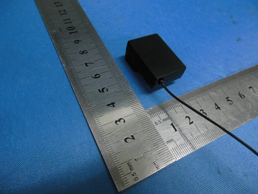
SNL-16005700
Jun 25, 20142.4 GHz Radio Control System
Equipment Class
DSS - Part 15 Spread Spectrum Transmitter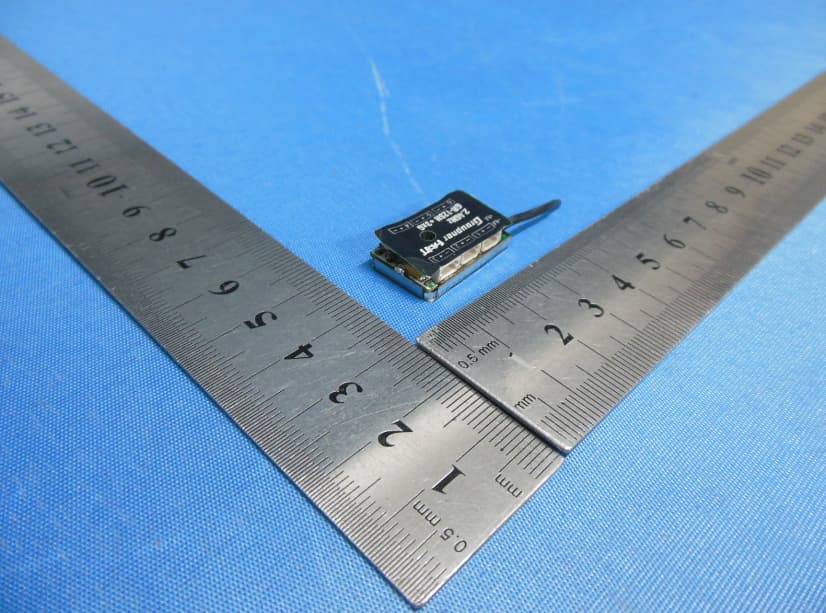
SNL-16006000
Jun 25, 20142.4 GHz Radio Control System
Equipment Class
DSS - Part 15 Spread Spectrum Transmitter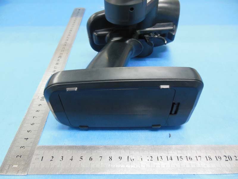
SNL-16005900
May 29, 20142.4GHz Radio Control Computer System
Equipment Class
DSS - Part 15 Spread Spectrum Transmitter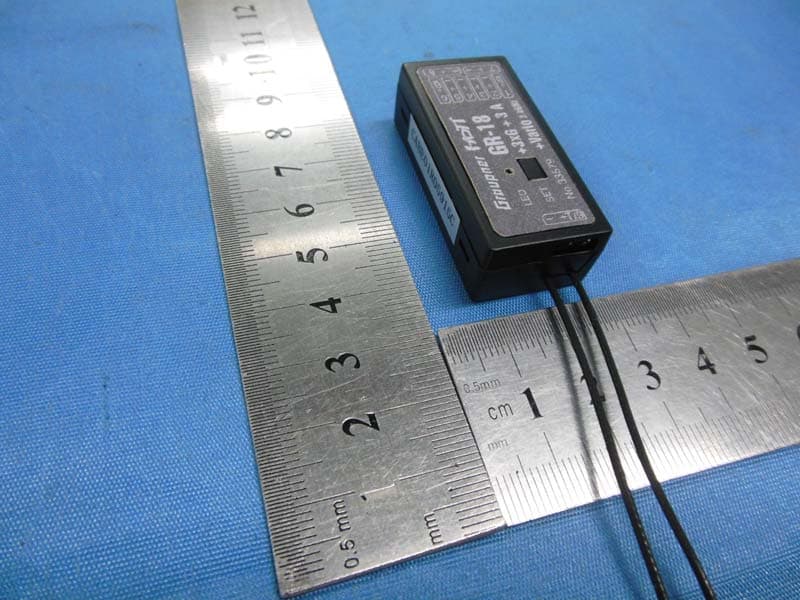
SNL-16006100
May 29, 20142.4GHz Radio Control Receiver
Equipment Class
DSS - Part 15 Spread Spectrum Transmitter