SNL-160059002.4GHz Radio Control Computer System
GRAUPNER CO., LTD.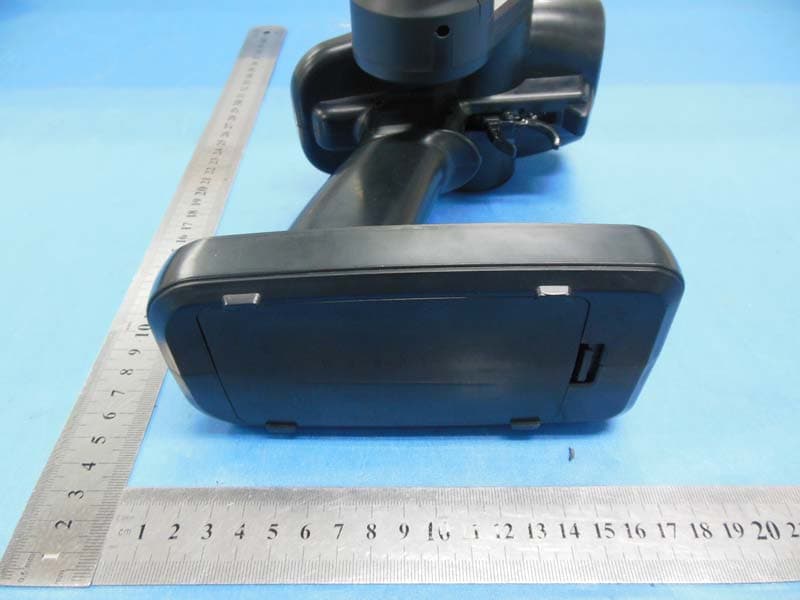
Click to zoom
Application Details
- Equipment Class
- DSS - Part 15 Spread Spectrum Transmitter
- Date of Grant
- May 29, 2014
- Application Purpose
- Original Equipment
- Date of Application
- May 29, 2014
- Equipment Note
- 2.4GHz Radio Control Computer System
- Frequency Range
- 2404.05600000 - 2474.02500000
- Company
- GRAUPNER CO., LTD.
- Country
- South Korea
Documents & Files
Document Text
Text extracted from the exhibit documents filed with the FCC. Open a document above to read the original.
Users Manual
FCC INFORMATION This device complies with Part 15 of the FCC Rules. Operation is subject to the following two conditions: 1. This device may not cause harmful interference, and 2. This device must accept any interference received, including interference that may cause undesired operation. Note: This equipment has been tested and found to comply with the limits for a Class B digital device, pursuant to part 15 of the FCC Rules. These limits are designed to provide reasonable protection against harmful interference in a residential installation. This equipment generates, uses and can radiate radio frequency energy and, if not installed and used in accordance with the instructions, may cause harmful interference to radio communications. However, there is no guarantee that interference will not occur in a particular installation. If this equipment does cause harmful interference to radio or television reception, which can be determined by turning the equipment off and on, the user is encouraged to try to correct the interference by one or more of the following measures: —Reorient or relocate the receiving antenna. —Increase the separation between the equipment and receiver. —Connect the equipment into an outlet on a circuit different from that to which the receiver is connected. —Consult the dealer or an experienced radio/TV technician for help. Caution: Any changes or modifications not expressly approved by the party responsible for compliance could void the user's authority to operate this equipment.
Users Manual
X-4S MANUAL Contents Before use------------------------------------------------------- • Support and Service----------------------------------------------- - Customer Support------------------------------------------------------------ - Internet sales site ----------------------------------------------------- - A/S support & Warranty information ------------------------------------------------------ - OPENHOBBY A/S SUPPORT AND SERVICE CENTER ------------- • Box Contents----------------------------------------------------------------- • Safety Warning Notes----------------------------------------------------------- • System Features----------------------------------------------------------------- • Specification------------------------------------------------------------------- • Product Description-------------------------------------------------------------- • HoTT • Operation • Receiver installation • Steering & Trigger tension adjustment • Steering wheel position adjustment • Trigger Angle Adjustment • Installation for left-handed users • Binding and Range test • Control Switch Functions-------------------------------------------------------------------P7 • Fail Safe mode Configuration ------------------------------------------------------------------------- • Trigger and Steering Calibration ------------------------------------------------------ • LED and Buzzer Indication------------------------------------------------------------------------ • Receiver port Description • Smart Box (Configuration by Telemetry) • Safety BEFORE USE Thank you for purchasing Graupner/SJ X-4S HoTT 2.4GHz Radio System. This system is extremely versatile and may be used by beginners and pros alike. In order for you to make the best use of your system, please read this manual carefully. If you have any difficulties while using your system, please consult the manual, our online Frequently Asked Questions (on the web pages referenced below), your hobby dealer, or the Graupner/SJ Service Center. Due to unforeseen changes in production procedures, the information contained in this manual is subject to change without notice. SUPPORT AND SERVICE • Customer support We are happy to assist you with any question by e-mail or phone, Customer service hours are 9 AM to 5 PM (Pacific Standard Time) during the workweek, Monday through Friday. E-mailed questions will be answered as soon as possible. • Internet sales site Please visit us at www.openhobbby.com , for more information • A/S support During the warranty period, we can repair this product at no cost for products that have become faulty under normal operating conditions. For non-functional products that are past the expiration date of the warranty or have been improperly used, we would be happy to repair this product for an appropriate amount of cost to the consumer • Warranty information Refer the WARRANTY CARD in the Package OPENHOBBY A/S SUPPORT AND SERVICE CENTER 기존 사용내용 기재 BOX CONTENTS X-4S HoTT Transmitter Warranty Card GR-4 Receiver Temperature / Voltage Sensor (S8362) Battery Holder Alkaline 4 cells Manual SAFETY WARNING NOTES • Never operate your car or truck in a crowded street with traffic. Especially, do not drive in a place near railway, chemical substance, gas to prevent any damage. • This product is not intended for use by inexperienced or disabled person without direct supervision of a responsible, knowledgeable adult. This is not suitable for children under 18 years. • This warranty does cover damaged products arising as a result of production process. It is not allowed to use to those who are the disabled or do not have enough knowledge. • The radio system is affected by signal environment and the electronic jamming signals can cause disorientation and loss of control of your aircraft. • Please read the manual to make the best use of the product • Make sure to check all operations of channels before use. • For the safe use, please operate the Range Check Mode before use. • Be careful not to turn your transmitter off while in use. • Do not touch or grab antenna during the use. • Do not operate your model in the rain or run through standing water • Fail Safe should be set before use to prevent uncontrollable situation occurred by any interruption. It is recommended to set throttle channel to Neutral condition or brake condition. • Always operate your program setup mode after stopping motor’s power or engine and disconnecting drive battery. • Make sure whenever you start operating your transmitter, turn your transmitter before switching your receiver switch. Whenever you stop your transmitter, turn your receiver off before your transmitter is switched off. • Always use new battery pack or charge your battery fully to avoid possible hazard causing by low battery capacity. • Always be sure to check your battery capacity for your transmitter and receiver. • As for boat model, we recommend installing your antenna vertically to the exterior boat and operating Range Check Mode for the best use of your model. System Features 1. HOPPING TELEMETRY TRANSMISSION (HoTT) The use of up to 35 hopping channels provides advanced reliable operation while keeping from any external interference. 2. Designed for beginners, X-4S HoTT Transmitter is the best choice for those who enjoy car, boat, and tank models. When optional Graupner/SJ Telemetry sensor or temperature sensor is used, you may check the real-time information such as model voltage, user programmable warnings. It is easy to check from your transmitter. 3. Unlike other binding systems which are widely used, X-4S HoTT Transmitter supports the fast binding system which is operated by pressing a button. Specifications (1) X-4S Transmitter Channel 2CH Operating Voltage 4.8 ~ 6.0V Battery Type Alkaline, Nixx 4 Cell Operating Current app. 65mA Operating Output Power App. 60 mW Frequency 2.4000 ~ 2.4835 GHz Modulation FHSS Operating Temperature app. -10 ~ +55`C ( app. -50 ~ +131°F ) Antenna Dipole Antenna Display LE…
Text truncated - open the document above for the full version.
Cover Letter(s)
Graupner CO.,Ltd Application for FCC ID: SNL-16005900 To whom it may concern: This communication port of this device is covered, and not for consumer use. Users cant upgrade the equipment. Possible country settings (if) referred to in the User Manual are not active / not implemented for the FCC version of this product. U.S. Users cannot bring the device out of compliance. Yours sincerely,
Cover Letter(s)
V V V
External Photos
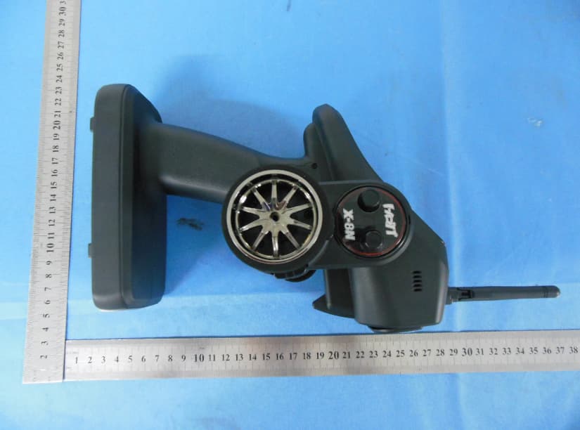
External Photographs EUT –Front View EUT – Rear View Antenna location EUT – Side View
ID Label/Location Info
FCC LABEL Location FCC LABEL Location
Internal Photos
Internal Photographs EUT - Open View EUT - PCB View EUT - PCB View EUT - PCB View
RF Exposure Info
FCC RF Exposure FCC ID: SNL-16005900 Frequency: 2404.056 - 2474.025 MHz (70 Ch) Mid-Channel: 2438.553 MHz Mid-Channel Peak Power, Conducted, highest valud measured: 16.88 dBm == 48.75 mW Antenna Gain: G = 1.2 dBi Peak, Radiated = 16.88 dBm + 1.2 dBi = 18.08 dBm = 64.27 mW SAR Test Exclusion Thresholds specified in KDB447498 Appendix A: Evaluation: Given the handgrip and position of the swivel antenna, it generally is more than 50mm from the human hand or human body while operating the device. The power this device generates is 64.27mW, thus below the 96mW that is allowed at 50mm. Conclusion: The emitted power appears to be below the required limit, so PASS.
Test Report
Test Report of FCC CFR 47 Part 15 Subpart C On Behalf of Graupner CO.,Ltd FCC ID: SNL-16005900 Product Description: 2.4GHz Radio Control Computer System Model No.: X-4S Supplementary Model: N/A Prepared for: Graupner CO.,Ltd 202Dong 8 th F,18, Bucheon-ro 198beon-gil, Wonmi-gu, Bucheon- si, Gyeonggi-do, Korea Prepared by: Bontek Compliance Testing Laboratory Co., Ltd 1/F, Block East H-3, OCT Eastern Ind. Zone, Qiaocheng East Road, Nanshan, Shenzhen, China Tel: 86-755-86337020 Fax: 86-755-86337028 Report No.: BCT14CR052E Issue Date: April 1, 2014 Test Date: March 12~ April 1, 2014 Tested by: Reviewed by: Lion Cai Owen Yang Approved by: Kendy Wang Report No.: BCT14CR052E Page 2 of 42 FCC ID: SNL-16005900 TABLE OF CONTENTS 1. GENERAL INFORMATION .................................................................................................................................... 4 1.1 PRODUCT DESCRIPTION FOR EQUIPMENT UNDER TEST (EUT) ......................................................................... 4 1.2 RELATED SUBMITTAL(S) / GRANT (S) AND TEST METHODOLOGY ....................................................................... 5 1.3 TEST FACILITY ...................................................................................................................................................... 5 2. SYSTEM TEST CONFIGURATION ...................................................................................................................... 6 2.1 EUT CONFIGURATION .......................................................................................................................................... 6 2.2 EUT EXERCISE ..................................................................................................................................................... 6 2.3 GENERAL TEST PROCEDURES ............................................................................................................................. 6 2.4 MEASUREMENT UNCERTAINTY ............................................................................................................................. 6 2.5TEST EQUIPMENT LIST AND DETAILS .................................................................................................................... 7 3. SUMMARY OF TEST RESULTS .......................................................................................................................... 7 4. TEST OF AC POWER LINE CONDUCTED EMISSION.................................................................................... 8 4.1 APPLICABLE STANDARD ....................................................................................................................................... 8 4.2 TEST SETUP DIAGRAM ......................................................................................................................................... 8 4.3 TEST RESULT ....................................................................................................................................................... 8 5. TEST OF HOPPING CHANNEL BANDWIDTH .................................................................................................. 9 5.1 APPLICABLE STANDARD ....................................................................................................................................... 9 5.2 EUT SETUP .......................................................................................................................................................... 9 5.3 TEST EQUIPMENT LIST AND DETAILS ................................................................................................................... 9 5.4 TEST PROCEDURE ................................................................................................................................................ 9 5.5 TEST RESULT ....................................................................................................................................................... 9 6. TEST OF HOPPING CHANNEL SEPARATION ............................................................................................... 12 6.1 APPLICABLE STANDARD ..................................................................................................................................... 12 6.2 EUT SETUP ........................................................................................................................................................ 12 6.3 TEST EQUIPMENT LIST AND DETAILS ................................................................................................................. 12 6.4 TEST PROCEDURE .............................................................................................................................................. 12 6.5 TEST RESULT ..................................................................................................................................................... 12 7. TEST OF NUMBER OF HOPPING FREQUENCY ........................................................................................... 15 7.1 APPLICABLE STANDARD ..................................................................................................................................... 15 7.2 EUT SETUP ........................................................................................................................................................ 15 7.3 TEST EQUIPMENT LIST AND DETAILS ................................................................................................................. 15 7.4 TEST PROCEDURE .............................................................................................................................................. 15 7.5 TEST RESULT ..................................................................................................................................................... 15 8. TEST OF DWELL TIME OF EACH FREQUENCY ..............................................…
Text truncated - open the document above for the full version.
Test Setup Photos
Test Setup Photos Radiated emission below 30MHz Radiated emission 30MHz~1GHz Radiated emission above 1GHz
Contact Information
Applicant
Durk Churl Gahng
Technical Contact
Test Firm
Shenzhen CTL Testing Technology Co., Ltd.Tracy Qi
[email protected]86-755-89486194
Technical Specifications
| # | Rule Parts | Frequency Range | Power Output |
|---|---|---|---|
| 1 | 15C | 2.40 GHz - 2.47 GHz | 48.75 mW |
Other Applications from GRAUPNER CO., LTD.
SNL-16006200
Jun 30, 20142.4 GHz Radio Control System
Equipment Class
DSS - Part 15 Spread Spectrum Transmitter
SNL-16005700
Jun 25, 20142.4 GHz Radio Control System
Equipment Class
DSS - Part 15 Spread Spectrum Transmitter
SNL-16006000
Jun 25, 20142.4 GHz Radio Control System
Equipment Class
DSS - Part 15 Spread Spectrum Transmitter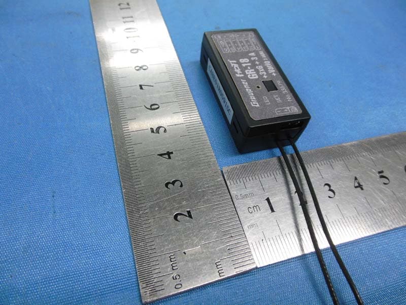
SNL-16006100
May 29, 20142.4GHz Radio Control Receiver
Equipment Class
DSS - Part 15 Spread Spectrum Transmitter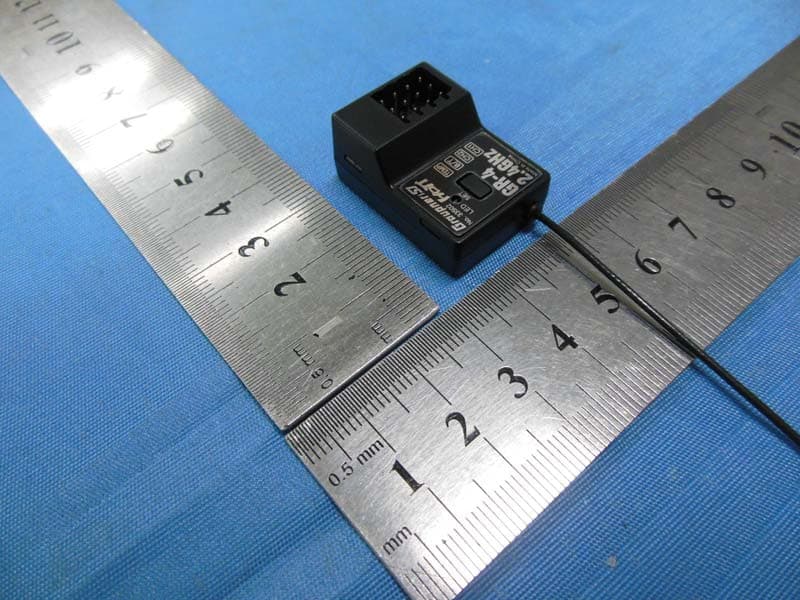
SNL-16005600
May 27, 20142.4 GHz Radio Control Receiver
Equipment Class
DSS - Part 15 Spread Spectrum Transmitter