SNL-160060002.4 GHz Radio Control System
GRAUPNER CO., LTD.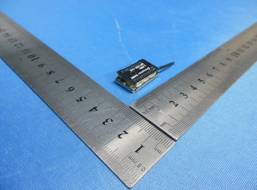
Click to zoom
Application Details
- Equipment Class
- DSS - Part 15 Spread Spectrum Transmitter
- Date of Grant
- Jun 25, 2014
- Application Purpose
- Original Equipment
- Date of Application
- Jun 25, 2014
- Equipment Note
- 2.4 GHz Radio Control System
- Frequency Range
- 2404.05600000 - 2474.02500000
- Company
- GRAUPNER CO., LTD.
- Country
- South Korea
Documents & Files
Document Text
Text extracted from the exhibit documents filed with the FCC. Open a document above to read the original.
Users Manual
FCC INFORMATION (additional) RF Exposure: A distance of 20 cm shall be maintained between the antenna and users, and the transmitter may not be co-located with any other transmitter or antenna.
Users Manual
1. Notes......................................................................................................................19 2. Functions...............................................................................................................21 2.1. Binding.........................................................................................................21 2.1.1 Binding multiple receivers...................................................................................21 2.2. Fail-Safe function...............................................................................................21 2.3 Range-checking...........................................................................................22 3. Receiver..................................................................................................................23 3.1. Connections..................................................................................................24 3.2. Receiver set-up menu........................................................................................25 3.3. Free mixers.......................................................................................................25 3.4 Assigning the gyro axes......................................................................................27 4. Programming the gyro settings...............................................................................29 4.1. Programming PID correction..............................................................................29 4.2. Programming the factors....................................................................................30 4.2.1 Programming, transmitter with proportional controls............................................30 4.2.2 Programming, transmitter without proportional controls.......................................31 4.3 Initialising the gyro............................................................................................31 5. Conformity declaration / Guarantee / Manufacturer’s declaration / Disposal..50 MANY THANKS for deciding to purchase the Graupner/SJ HoTT 2.4 system. Please read right through these operating instructions before you attempt to install and operate the Graupner HoTT 2.4 system. • The receiver stabilises the model aircraft in difficult, windy conditions, acting on a maximum of three axes • Proportional gyro suppression for natural flying characteristics • Excellent stabilisation for smooth, accurate manoeuvres • The triple-axis gyro endows even very demanding aerobatic models with docile flying characteristics, and greatly simplifies aerobatics • Aerobatic manoeuvres can be flown much more accurately • Simple gyro assignment procedure • Facility to adjust parameters using HoTT telemetry • Altitude sensor for vario and altimeter function (Order No. 33577) 1. APPROVED USAGE The receiver is intended exclusively for use in radio-controlled models. Any other usage is prohibited, and may result in damage to the receiver or model, and serious personal injury. We grant no guarantee and accept no liability for any type of use outside the stipulated range. Not suitable for children under fourteen years. This receiver is not a toy! The receiver is also equipped with a telemetry function which is only available in combination with a Graupner/SJ HoTT 2.4 system. If you do not own a Graupner/SJ HoTT 2.4 system, the receiver will not work. Please start by reading through the whole instructions before you attempt to install and operate the receiver. These operating instructions are an integral part of the product. They contain important notes on operating and handling the receiver. For this reason please store the operating instructions in a safe place, and pass them on to the new owner if you ever dispose of the product. Failure to observe the operating instructions and safety notes invalidates the guarantee. Here at Graupner we are constantly working on the further development of all our products; for this reason we are obliged to reserve the right to introduce changes to the set contents in form, technology and features. Please understand that we will not countenance claims resulting from information and illustrations in these operating instructions. Please store the operating instructions in a safe place for future reference! 1.1 SAFETY NOTES KEY TO THE SYMBOLS 1.2 GENERAL NOTES • The receiver’s integral gyros are very fast, high-resolution components. This means that you should always use high-speed digital servos wherever possible, so that the gyro’s corrective signals are converted directly and accurately into servo movement; this helps to prevent the model oscillating. • Keep all servo extension leads as short as possible. • When switching on or adjusting the radio control system, it is essential to keep the transmitter aerial at least 15 cm from the receiver aerial(s). If the transmitter aerial is too close to the receiver aerials, the receiver will be swamped and the red LED on the receiver will light up. The transmitter responds with a flashing red LED and repeated beeps at approximately one-second intervals, i.e. the radio control system reverts to fail-safe mode. If this should happen, increase the distance until the audible warning ceases, and the blue transmitter LED lights up constantly once more. The red LED on the receiver should now be off. 2. FUNCTIONS 2.1. Binding The Graupner/SJ HoTT 2.4 receiver must be “bound” to “its” Graupner/SJ HoTT 2.4 RF module (transmitter) before a radio link can be created between them; this process is known as “binding”. Binding is only necessary once for each combination of receiver / RF module, so the binding procedure described below only needs to be repeated if you add more receivers. However, binding can be repeated at any time if you wish; for example, if you switch transmitters. This is the procedure in detail: • Binding is only possible if the receiver has not been linked with a bound transmitt…
Text truncated - open the document above for the full version.
Cover Letter(s)
Graupner CO.,Ltd FCC Authorization Letter Number: CF304 Version: V03 Date: 01-08-2011 We, (the approval holder) Company name Graupner CO.,Ltd Address 8 th F,202 Dong,Chunui Techno-Park2,18, Bucheon-ro 198beon-gil,Wonmi-gu City Bucheon-shi,Kyungki-do Country South Korea declare that the following representative (agent): Name (person) Tony Wu Company name Bontek Compliance Laboratory Co., Ltd. Address 1/F, Block East H-3,OCT Eastern Ind. Zone, Qiaocheng East Road, Nanshan, City Shenzhen,Guangdong Country China is hereby authorized to apply the following equipment for certification on our behalf: Product Description 2.4GHz Radio Control System Type or Model(s) GR-12SH+3xG Tradename or Brand(s) HoTT We also authorize Teleconformity (Mr. M. Koop, Manager Certification, Address: Rietven 31, 7534NH Enschede, the Netherlands) to apply and sign this application for certification, registration or filing on our behalf (as representative agent or certifier). Attestation: City and Country: Date: Name: (this must be a person) Function:Signature: (or official company stamp) SHEN ZHEN 2014-06-01 Durk Churl Gahng manager
External Photos
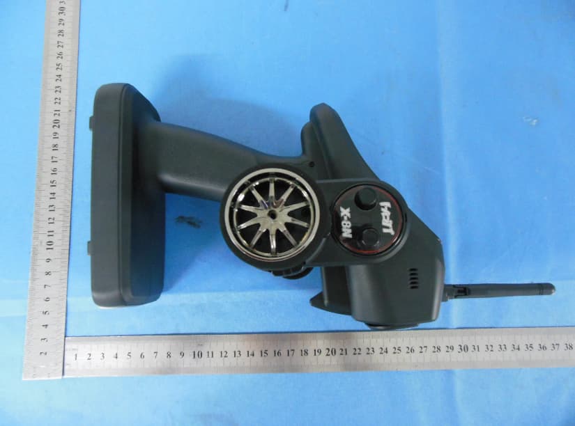
External Photographs EUT –Front View EUT – Rear View EUT – Side View
ID Label/Location Info
6.2 MAT'L Q'TY DWG.NO SCALE DATE 2014.03.06Q'TY MODEL NAME UNIT mm PART DESCRIPTION SPECIFICATION REMARK GR-12SH+3xG Assembly 24.0 27.0 15.0 NAME UNIT mm PART APP.BY MAT'L BOM NO. CUSTOME R SHEET A4 Assembly SJ INCORPORATED
Internal Photos
Internal Photographs EUT - Open View EUT - PCB View Antenna location
Test Report
Test Report of FCC CFR 47 Part 15 Subpart C On Behalf of Graupner CO.,Ltd FCC ID: SNL-16006000 Product Description: 2.4GHz Radio Control Receiver Model No.: GR-12SH+3XG Supplementary Model: N/A Prepared for: Graupner CO.,Ltd 8 th F,202 Dong,Chunui Techno-Park2,18, Bucheon-ro 198beon- gil,Wonmi-gu,Bucheon-shi,Kyungki-do, South Korea Prepared by: Bontek Compliance Testing Laboratory Co., Ltd 1/F, Block East H-3, OCT Eastern Ind. Zone, Qiaocheng East Road, Nanshan, Shenzhen, China Tel: 86-755-86337020 Fax: 86-755-86337028 Report No.: BCT14ER202E Issue Date: June 10, 2014 Test Date: May21~ June 10, 2014 Tested by: Reviewed by: Jiankuai.Li Owen Yang Approved by: Kendy Wang Report No.: BCT14ER202E Page 2 of 42 FCC ID: SNL-16006000 TABLE OF CONTENTS 1. GENERAL INFORMATION .................................................................................................................................... 4 1.1 PRODUCT DESCRIPTION FOR EQUIPMENT UNDER TEST (EUT) ......................................................................... 4 1.2 RELATED SUBMITTAL(S) / GRANT (S) AND TEST METHODOLOGY ....................................................................... 5 1.3 TEST FACILITY ...................................................................................................................................................... 5 FCC – REGISTRATION NO.: 970318 ......................................................................................................................... 5 2. SYSTEM TEST CONFIGURATION ...................................................................................................................... 6 2.1 EUT CONFIGURATION .......................................................................................................................................... 6 2.2 EUT EXERCISE ..................................................................................................................................................... 6 2.3 GENERAL TEST PROCEDURES ............................................................................................................................. 6 2.4 MEASUREMENT UNCERTAINTY ............................................................................................................................. 6 2.5TEST EQUIPMENT LIST AND DETAILS .................................................................................................................... 7 3. SUMMARY OF TEST RESULTS .......................................................................................................................... 7 4. TEST OF AC POWER LINE CONDUCTED EMISSION.................................................................................... 8 4.1 APPLICABLE STANDARD ....................................................................................................................................... 8 4.2 TEST SETUP DIAGRAM ......................................................................................................................................... 8 4.3 TEST RESULT ....................................................................................................................................................... 8 5. TEST OF HOPPING CHANNEL BANDWIDTH .................................................................................................. 9 5.1 APPLICABLE STANDARD ....................................................................................................................................... 9 5.2 EUT SETUP .......................................................................................................................................................... 9 5.3 TEST EQUIPMENT LIST AND DETAILS ................................................................................................................... 9 5.4 TEST PROCEDURE ................................................................................................................................................ 9 5.5 TEST RESULT ....................................................................................................................................................... 9 6. TEST OF HOPPING CHANNEL SEPARATION ............................................................................................... 12 6.1 APPLICABLE STANDARD ..................................................................................................................................... 12 6.2 EUT SETUP ........................................................................................................................................................ 12 6.3 TEST EQUIPMENT LIST AND DETAILS ................................................................................................................. 12 6.4 TEST PROCEDURE .............................................................................................................................................. 12 6.5 TEST RESULT ..................................................................................................................................................... 12 7. TEST OF NUMBER OF HOPPING FREQUENCY ........................................................................................... 15 7.1 APPLICABLE STANDARD ..................................................................................................................................... 15 7.2 EUT SETUP ........................................................................................................................................................ 15 7.3 TEST EQUIPMENT LIST AND DETAILS ................................................................................................................. 15 7.4 TEST PROCEDURE .............................................................................................................................................. 15 7.5 TEST RESULT ............................................................…
Text truncated - open the document above for the full version.
Test Setup Photos
Test Setup Photos Radiated emission below 30MHz Radiated emission 30MHz~1GHz Radiated emission above 1GHz
Contact Information
Applicant
Durk Churl Gahng
Technical Contact
Test Firm
Shenzhen CTL Testing Technology Co., Ltd.Tracy Qi
[email protected]86-755-89486194
Technical Specifications
| # | Rule Parts | Frequency Range | Power Output |
|---|---|---|---|
| 1 | 15C | 2.40 GHz - 2.47 GHz | 1.82 mW |
Other Applications from GRAUPNER CO., LTD.
SNL-16006200
Jun 30, 20142.4 GHz Radio Control System
Equipment Class
DSS - Part 15 Spread Spectrum Transmitter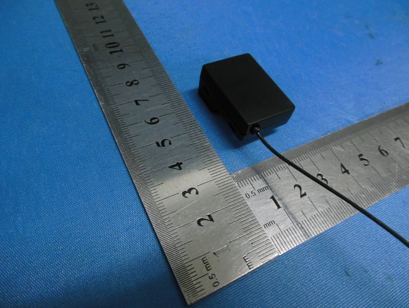
SNL-16005700
Jun 25, 20142.4 GHz Radio Control System
Equipment Class
DSS - Part 15 Spread Spectrum Transmitter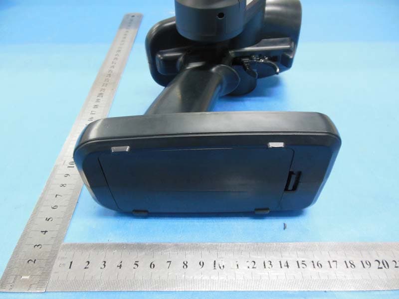
SNL-16005900
May 29, 20142.4GHz Radio Control Computer System
Equipment Class
DSS - Part 15 Spread Spectrum Transmitter
SNL-16006100
May 29, 20142.4GHz Radio Control Receiver
Equipment Class
DSS - Part 15 Spread Spectrum Transmitter
SNL-16005600
May 27, 20142.4 GHz Radio Control Receiver
Equipment Class
DSS - Part 15 Spread Spectrum Transmitter