SNL-160049002.4 GHz Radio Control Computer System
GRAUPNER CO., LTD.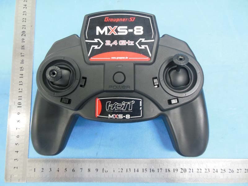
Click to zoom
Application Details
- Equipment Class
- DSS - Part 15 Spread Spectrum Transmitter
- Date of Grant
- May 27, 2014
- Application Purpose
- Original Equipment
- Date of Application
- May 27, 2014
- Equipment Note
- 2.4 GHz Radio Control Computer System
- Frequency Range
- 2404.05600000 - 2479.09500000
- Company
- GRAUPNER CO., LTD.
- Country
- South Korea
Documents & Files
Document Text
Text extracted from the exhibit documents filed with the FCC. Open a document above to read the original.
Users Manual
Programmier-Handbuch S.2-25 Programming Manual S.26-49 Manuel de programmation S.50-73 33200 mxs-8 - 33201 mxs-12.HoTT.1 mxs-8 mx s-12 Allgemeine Hinweise Sicherheitshinweise, bitte unbedingt beachten!............... 3 Symbole und deren Bedeutung....................................... 3 Sicherheitshinweise und Behandlungsvorschriften für Batterien..................................................................... 7 Vorwort............................................................................. 8 Beschreibung des Fernlenksets.......................................9 Technische Daten...........................................................10 Betriebshinweise.............................................................12 Sender-Stromversorgung.......................................12 Laden eines (optionalen) Senderakkus.................. 12 Einsetzen der Senderbatterien oder -akkus...........12 Entnahme der Senderbatterien -akkus...................12 Modeeinstellung......................................................12 Sendergehäuse zu Modeeinstellung öffnen............13 Umstellen der Kreuzknüppel...................................14 Senderbeschreibung...................................................... 15 Bedienelemente........................................................15 Inbetriebnahme des Senders......................................... 16 Firmware-Update des Senders.............................. 17 Inbetriebnahme des Empfängers................................... 17 Einbau des Empfängers.........................................17 Stromversorgung des Empfängers..........................18 Weitere Empfängerfunktionen.................................20 Update der Empfänger-Firmware............................20 Begriffsdefinitionen........................................................ 20 Grundeinstellung des Senders.......................................21 Steueranordnung ...........................................21 Binden von Sender und Empfänger................21 „Binding“ mehrerer Empfänger pro Modell......21 Reichweitetest ................................................22 »Servoeinstellung« ......................................................23 Servodrehrichtung...................................................23 Servoweg................................................................23 »Fail Safe Einstellung« ...............................................24 Digitale Trimmung.......................................................... 24 Anhang Herstellererklärung.........................................................25 Konformitätserklärung ...................................................26 Garantieurkunde ............................................................27 2 Hinweise zum Umweltschutz Das Symbol auf dem Produkt, der Gebrauchsanleitung oder der Verpackung weist darauf hin, dass dieses Produkt am Ende seiner Lebensdauer nicht über den nor- malen Haushaltsabfall entsorgt werden darf. Es muss an einem Sammelpunkt für das Recycling von elektrischen und elektronischen Geräten abgegeben werden. Die Werkstoffe sind gemäß ihrer Kennzeichnung wiederverwertbar. Mit der Wiederverwendung, der stofflichen Verwertung oder anderen Formen der Verwertung von Altgeräten leisten Sie einen wichtigen Beitrag zum Umweltschutz. Batterien und Akkus müssen aus dem Gerät entfernt werden und bei einer entsprechenden Sammelstelle getrennt entsorgt werden. Bitte erkundigen Sie sich ggf. bei der Gemeindeverwaltung nach der zuständigen Entsorgungsstelle. Dieses Handbuch dient ausschließlich Informationszwe- cken und kann ohne Vorankündigung geändert werden. Die Firma Graupner/SJ GmbH übernimmt keine Verant- wortung oder Haftung für Fehler bzw. Ungenauigkeiten, die in diesem Handbuch auftreten können. Inhaltsverzeichnis Inhaltsverzeichnis 3 Sicherheitshinweise Sicherheitshinweise Bitte unbedingt beachten! Um noch lange Freude an Ihrem Modellbauhobby zu haben, lesen Sie diese Anleitung unbedingt genau durch und beachten Sie vor allem die Sicherheitshinweise. Auch sollten Sie sich umgehend unter http://www.graupner.de/ de/service/produktregistrierung registrieren, denn nur so erhalten Sie automatisch per E-Mail aktuelle Informatio- nen zu Ihrem Produkt. Wenn Sie Anfänger im Bereich ferngesteuerter Modell- flugzeuge, -schiffe oder -autos sind, sollten Sie unbedingt einen erfahrenen Modellpiloten um Hilfe bitten. Diese Anleitung ist bei Weitergabe des Senders unbe- dingt mit auszuhändigen. Anwendungsbereich Diese Fernsteueranlage darf ausschließlich nur für den vom Hersteller vorgesehenen Zweck, für den Betrieb in nicht manntragenden Fernsteuermodellen eingesetzt werden. Eine anderweitige Verwendung ist unzulässig. Sicherheitshinweise SICHERHEIT IST KEIN ZUFALL und FERNGESTEUERTE MODELLE SIND KEIN SPIELZEUG ... denn auch kleine Modelle können durch unsachge- mäße Handhabung, aber auch durch fremdes Ver- schulden, erhebliche Sach- und/oder Personenschäden verursachen. Technische Defekte elektrischer oder mechanischer Art können zum unverhofften Anlaufen eines Motors und/ oder zu herumfliegenden Teilen führen, die nicht nur Sie erheblich verletzen können! Kurzschlüsse jeglicher Art sind unbedingt zu vermeiden! Durch Kurzschluss können nicht nur Teile der Fernsteu- erung zerstört werden, sondern je nach dessen Umstän- den und dem Energiegehalt des Akkus besteht darüber hinaus akute Verbrennungs- bis Explosionsgefahr. Alle durch einen Motor angetriebenen Teile wie Luft- und Schiffsschrauben, Rotoren bei Hubschraubern, offene Getriebe usw. stellen eine ständige Verletzungsgefahr dar. Sie dürfen keinesfalls berührt werden! Eine schnell dre- hende Luftschraube kann z. B. einen Finger abschlagen! Achten Sie darauf, dass auch kein sonstiger Gegenstand mit angetriebenen Teilen in Berührung kommt! Bei angeschlossenem Antriebsakku oder laufendem Mo- tor gilt: Halten Sie sich niemals im Gefährdungsbereich des Antriebs auf! Achten Sie auch während der Programmierung un bedingt darauf, dass ein an…
Text truncated - open the document above for the full version.
Users Manual
FCC INFORMATION This device complies with Part 15 of the FCC Rules. Operation is subject to the following two conditions: 1. This device may not cause harmful interference, and 2. This device must accept any interference received, including interference that may cause undesired operation. Note: This equipment has been tested and found to comply with the limits for a Class B digital device, pursuant to part 15 of the FCC Rules. These limits are designed to provide reasonable protection against harmful interference in a residential installation. This equipment generates, uses and can radiate radio frequency energy and, if not installed and used in accordance with the instructions, may cause harmful interference to radio communications. However, there is no guarantee that interference will not occur in a particular installation. If this equipment does cause harmful interference to radio or television reception, which can be determined by turning the equipment off and on, the user is encouraged to try to correct the interference by one or more of the following measures: —Reorient or relocate the receiving antenna. —Increase the separation between the equipment and receiver. —Connect the equipment into an outlet on a circuit different from that to which the receiver is connected. —Consult the dealer or an experienced radio/TV technician for help. Caution: Any changes or modifications not expressly approved by the party responsible for compliance could void the user's authority to operate this equipment. RF Exposure: A distance of 20 cm shall be maintained between the antenna and users, and the transmitter may not be co-located with any other transmitter or antenna.
Cover Letter(s)
Graupner CO.,Ltd Application for FCC ID: SNL-16004900 To whom it may concern: This communication port of this device is covered, and not for consumer use. Users cant upgrade the equipment. Yours sincerely,
Cover Letter(s)
Graupner CO.,Ltd FCC Authorization Letter Number: CF304 Version: V03 Date: 01-08-2011 We, (the approval holder) Company name Graupner CO.,Ltd Address 202Dong 8th F,18, Bucheon-ro 198beon-gil, Wonmi-gu, City Bucheon-si, Gyeonggi-do Country Korea declare that the following representative (agent): Name (person) Tony Wu Company name Bontek Compliance Laboratory Co., Ltd. Address 1/F, Block East H-3,OCT Eastern Ind. Zone, Qiaocheng East Road, Nanshan, City Shenzhen,Guangdong Country China is hereby authorized to apply the following equipment for certification on our behalf: Product Description 2.4GHz Radio Control Computer System Type or Model(s) MXS-8 Tradename or Brand(s) HoTT We also authorize Teleconformity (Mr. M. Koop, Manager Certification, Address: Rietven 31, 7534NH Enschede, the Netherlands) to apply and sign this application for certification, registration or filing on our behalf (as representative agent or certifier). Attestation: City and Country: Date: Name: (this must be a person) Function:Signature: (or official company stamp) SHEN ZHEN 2014-04-01 Durk Churl Gahng manager
Cover Letter(s)
V V V
External Photos
External Photographs EUT –Front View EUT – Rear View EUT – Side View
ID Label/Location Info
FCC ID LABEL Location FCC ID LABEL Location
Internal Photos
Internal Photographs EUT - Open View EUT - PCB View Antenna location EUT - PCB View EUT - PCB View EUT – Button PCB View
RF Exposure Info
FCC RF Exposure FCC ID: SNL-16005900 Frequency: 2404.056 - 2479.095 MHz (75 Ch) Mid-Channel: 2440.561 MHz Mid-Channel Peak Power, Conducted, highest valud measured: 16.56 dBm == 45.3 mW Antenna Gain: G = 1.5 dBi Peak, Radiated = 16.56 dBm + 1.5 dBi = 18.06 dBm = 63.79 mW SAR Test Exclusion Thresholds specified in KDB447498 Appendix A: Evaluation: Refer to the photos on the next page. Given the position to hold the remote control in front of you with two hands, using left and right hand finger to use the steering handles, the internal antenna is generally is more than 50mm from the human finger. When holding the device fully against the body during operation (belly/chest), the antenna is still 20cm away from the body. This is the reason the user manual contains the 20cm RF exposure 20cm warning. The power this device generates is 63.97mW, thus below the 96mW that is allowed at 50mm. For body position, the MPE shows that the power density is far below 1 and passes, see MPE calculation below: Frequency range:2404.056 - 2479.095MHzWhen using at distance of: d ≥20cm Power density limit for mobile devices at 2.4 GHz: S ≤1mW/cm 2 Maximum measured conducted power (Peak): Pconducted =16.56dBm =45.29mW Antenna Gain: G = 1.5dBi =1.41on the linear scale Calculation: P radiated = P conducted + G linear =16.56 dBm + 1.5 dBi =18.06dBm =63.97mW Power density S = (P radiated ) / (4π x d 2 ) = 63.97/5026 =0.0127 mW/cm 2 <1 => below limit 5 cm distance to finger 20 cm distance hand/body (worst case)
Test Report
Test Report of FCC CFR 47 Part 15 Subpart C On Behalf of Graupner CO.,Ltd FCC ID: SNL-16004900 Product Description: 2.4GHz Radio Control Computer System Model No.: MXS-8 Supplementary Model: N/A Prepared for: Graupner CO.,Ltd 202Dong 8 th F,18, Bucheon-ro 198beon-gil, Wonmi-gu, Bucheon- si, Gyeonggi-do, Korea Prepared by: Bontek Compliance Testing Laboratory Co., Ltd 1/F, Block East H-3, OCT Eastern Ind. Zone, Qiaocheng East Road, Nanshan, Shenzhen, China Tel: 86-755-86337020 Fax: 86-755-86337028 Report No.: BCT14CR049E Issue Date: March 31, 2014 Test Date: March 12~ 31, 2014 Tested by: Reviewed by: Lion Cai Owen Yang Approved by: Kendy Wang Report No.: BCT14CR049E Page 2 of 42 FCC ID: SNL-16004900 TABLE OF CONTENTS 1. GENERAL INFORMATION .................................................................................................................................... 4 1.1 PRODUCT DESCRIPTION FOR EQUIPMENT UNDER TEST (EUT) ......................................................................... 4 1.2 RELATED SUBMITTAL(S) / GRANT (S) AND TEST METHODOLOGY ....................................................................... 4 1.3 TEST FACILITY ...................................................................................................................................................... 5 2. SYSTEM TEST CONFIGURATION ...................................................................................................................... 6 2.1 EUT CONFIGURATION .......................................................................................................................................... 6 2.2 EUT EXERCISE ..................................................................................................................................................... 6 2.3 GENERAL TEST PROCEDURES ............................................................................................................................. 6 2.4 MEASUREMENT UNCERTAINTY ............................................................................................................................. 6 2.5TEST EQUIPMENT LIST AND DETAILS .................................................................................................................... 7 3. SUMMARY OF TEST RESULTS .......................................................................................................................... 7 4. TEST OF AC POWER LINE CONDUCTED EMISSION.................................................................................... 8 4.1 APPLICABLE STANDARD ....................................................................................................................................... 8 4.2 TEST SETUP DIAGRAM ......................................................................................................................................... 8 4.3 TEST RESULT ....................................................................................................................................................... 8 5. TEST OF HOPPING CHANNEL BANDWIDTH .................................................................................................. 9 5.1 APPLICABLE STANDARD ....................................................................................................................................... 9 5.2 EUT SETUP .......................................................................................................................................................... 9 5.3 TEST EQUIPMENT LIST AND DETAILS ................................................................................................................... 9 5.4 TEST PROCEDURE ................................................................................................................................................ 9 5.5 TEST RESULT ....................................................................................................................................................... 9 6. TEST OF HOPPING CHANNEL SEPARATION ............................................................................................... 12 6.1 APPLICABLE STANDARD ..................................................................................................................................... 12 6.2 EUT SETUP ........................................................................................................................................................ 12 6.3 TEST EQUIPMENT LIST AND DETAILS ................................................................................................................. 12 6.4 TEST PROCEDURE .............................................................................................................................................. 12 6.5 TEST RESULT ..................................................................................................................................................... 12 7. TEST OF NUMBER OF HOPPING FREQUENCY ........................................................................................... 15 7.1 APPLICABLE STANDARD ..................................................................................................................................... 15 7.2 EUT SETUP ........................................................................................................................................................ 15 7.3 TEST EQUIPMENT LIST AND DETAILS ................................................................................................................. 15 7.4 TEST PROCEDURE .............................................................................................................................................. 15 7.5 TEST RESULT ..................................................................................................................................................... 15 8. TEST OF DWELL TIME OF EACH FREQUENCY .................................................…
Text truncated - open the document above for the full version.
Test Setup Photos
Test Setup Photos Radiated emission below 30MHz Radiated emission 30MHz~1GHz Radiated emission above 1GHz
Contact Information
Applicant
Durk Churl Gahng
Technical Contact
Test Firm
Shenzhen CTL Testing Technology Co., Ltd.Tracy Qi
[email protected]86-755-89486194
Technical Specifications
| # | Rule Parts | Frequency Range | Power Output |
|---|---|---|---|
| 1 | 15C | 2.40 GHz - 2.48 GHz | 45.30 mW |
Other Applications from GRAUPNER CO., LTD.
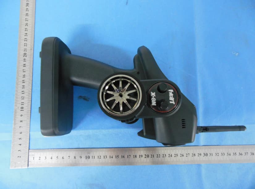
SNL-16006200
Jun 30, 20142.4 GHz Radio Control System
Equipment Class
DSS - Part 15 Spread Spectrum Transmitter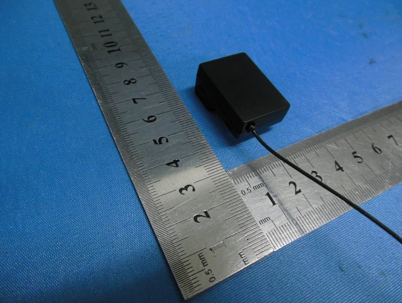
SNL-16005700
Jun 25, 20142.4 GHz Radio Control System
Equipment Class
DSS - Part 15 Spread Spectrum Transmitter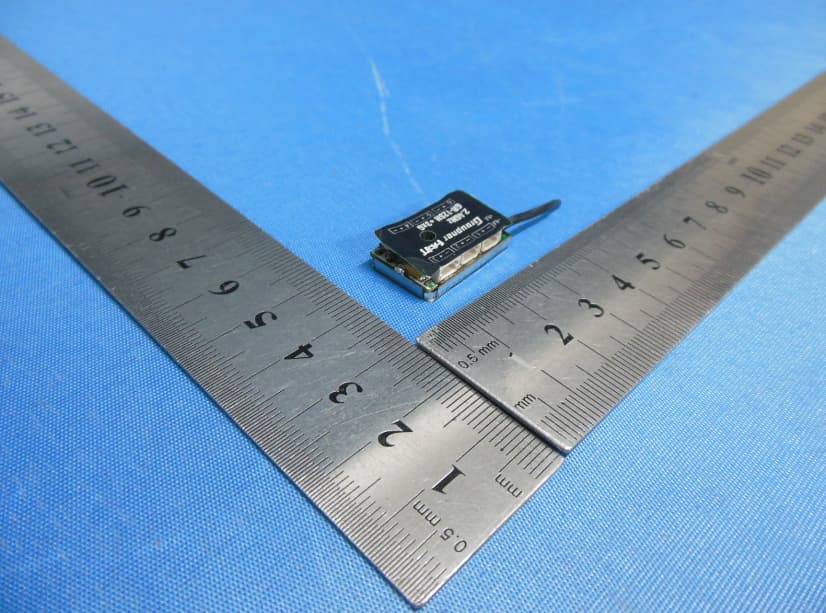
SNL-16006000
Jun 25, 20142.4 GHz Radio Control System
Equipment Class
DSS - Part 15 Spread Spectrum Transmitter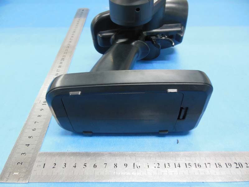
SNL-16005900
May 29, 20142.4GHz Radio Control Computer System
Equipment Class
DSS - Part 15 Spread Spectrum Transmitter
SNL-16006100
May 29, 20142.4GHz Radio Control Receiver
Equipment Class
DSS - Part 15 Spread Spectrum Transmitter