SNL-16005500Gyro Receiver Graupner/SJ HoTT
GRAUPNER CO., LTD.
Click to zoom
Application Details
- Equipment Class
- DSS - Part 15 Spread Spectrum Transmitter
- Date of Grant
- Dec 01, 2013
- Application Purpose
- Original Equipment
- Date of Application
- Dec 01, 2013
- Equipment Note
- Gyro Receiver Graupner/SJ HoTT
- Frequency Range
- 2404.05600000 - 2474.02500000
- Company
- GRAUPNER CO., LTD.
- Country
- South Korea
Documents & Files
Document Text
Text extracted from the exhibit documents filed with the FCC. Open a document above to read the original.
Users Manual
GRAUPNER/SJ GmbH – Postfach 1242 – 73230 Kirchheim/Teck – www.graupner.de Operating Instructions 33575Receiver GR-12 SH +3xG 33576Receiver GR-12 +3xG 33577Receiver GR-12 +3xG+3A+Vario 1. Notes......................................................................................................................02 2. Functions...............................................................................................................04 2.1. Binding.........................................................................................................04 2.1.1 Binding multiple receivers...................................................................................04 2.2. Fail-Safe function...............................................................................................04 2.3 Range-checking...........................................................................................05 3. Receiver..................................................................................................................06 3.1. Connections..................................................................................................07 3.2. Receiver set-up menu........................................................................................08 3.3. Free mixers.......................................................................................................08 3.4 Assigning the gyro axes......................................................................................10 4. Programming the gyro settings...............................................................................12 4.1. Programming PID correction..............................................................................12 4.2. Programming the factors....................................................................................13 4.2.1 Programming, transmitter with proportional controls............................................13 4.2.2 Programming, transmitter without proportional controls.......................................14 4.3 Initialising the gyro .....................................................................................................14 5. Firmware update..............................................................................................16 6. Conformity declaration / Guarantee / Manufacturer’s declaration / Disposal..17 Manual V1.0 Revision: Januar 2013 MANY THANKS for deciding to purchase the Graupner/SJ HoTT 2.4 system. Please read right through these operating instructions before you attempt to install and operate the Graupner HoTT 2.4 system. • The receiver stabilises the model aircraft in difficult, windy conditions, acting on a maximum of three axes • Proportional gyro suppression for natural flying characteristics • Excellent stabilisation for smooth, accurate manoeuvres • The triple-axis gyro endows even very demanding aerobatic models with docile flying characteristics, and greatly simplifies aerobatics • Aerobatic manoeuvres can be flown much more accurately • Simple gyro assignment procedure • Facility to adjust parameters using HoTT telemetry • Altitude sensor for vario and altimeter function (Order No. 33577) 1. APPROVED USAGE The receiver is intended exclusively for use in radio-controlled models. Any other usage is prohibited, and may result in damage to the receiver or model, and serious personal injury. We grant no guarantee and accept no liability for any type of use outside the stipulated range. Not suitable for children under fourteen years. This receiver is not a toy! The receiver is also equipped with a telemetry function which is only available in combination with a Graupner/SJ HoTT 2.4 system. If you do not own a Graupner/SJ HoTT 2.4 system, the receiver will not work. Please start by reading through the whole instructions before you attempt to install and operate the receiver. These operating instructions are an integral part of the product. They contain important notes on operating and handling the receiver. For this reason please store the operating instructions in a safe place, and pass them on to the new owner if you ever dispose of the product. Failure to observe the operating instructions and safety notes invalidates the guarantee. Here at Graupner we are constantly working on the further development of all our products; for this reason we are obliged to reserve the right to introduce changes to the set contents in form, technology and features. Please understand that we will not countenance claims resulting from information and illustrations in these operating instructions. Please store the operating instructions in a safe place for future reference! 1.1 SAFETY NOTES KEY TO THE SYMBOLS Caution! This symbol alerts you to prohibited actions which must be observed at all times. Any failure to observe the prohibited action indicated in this way may prevent the equipment working, and endanger the safety of the operator. Caution! This symbol alerts you to information which must be observed at all times. Any failure to observe the information indicated in this way may prevent the equipment working properly, and endanger the safety of the operator. This symbol indicates information which should always be observed in order to ensure that the equipment operates reliably. Manual Receiver GR-12+ 3xG Graupner HoTT 2. 4 2 Manual Receiver GR-12+ 3xG Graupner HoTT 2. 4 3 SAFETY NOTES Warning! The receiver must never be operated under the influence of medication, alcohol, drugs etc. Caution! Any deviation from the instructions may have an adverse effect on the function and operational security of the receiver, and must be avoided under all circumstances. Caution! The operator bears full responsibility for using the receiver. The only way to guard against personal injury and property damage is to handle the equipment carefully and use it exactly as recommended. Caution! Not suitable for children under fourteen years. Caution! Protect the receiver from d…
Text truncated - open the document above for the full version.
Cover Letter(s)
SJ Incorporated FCC Confidentiality Request (Permanent or also called long term confidentiality is the normal method to keep certain docuements confidential, and may apply to schematics, block diagrams, operational description and bill of materials.) To: Federal Communications Commission Equipment Authorization Branch 7435 Oakland Mills Road Columbia, MD 21046 Pursuant to 47 CFR Section 0.459(a) & (b), we, (the applicant / grantee) Company name SJ Incorporated Address 8th F,202 Dong,Chunui Techno-Park2,202,Chuni-Dong, City Wonmi-Gu,Bucheon-Shi,Kyungki-Do Country South Korea request for this certification filing under: Grantee Code Product Number FCC ID: SNL 16005500 to maintain permanent confidentiality for the following documents submitted within this application: (please cross what is applicable, or add other documents, provide the file name and description) Exhibit File Name Description Operational Description SNL-16005500_CircuitDescription.pdf explaining the functioning of the block diagram Block Diagrams SNL-16005500_Block Diagram.pdf showing the systematic building blocks of the EUT Schematics Diagrams SNL-16005500 _Schematic Diagram.pdfshowing components, their values and interconnection Bill of Materials List of components used on the PCB’s of the EUT Above materials crossed contain secrets, proprietary and technical information, which would customarily be guarded from competitors under 47 CFR, section 0.457(d)(2). Disclosure or publication or any portion of this company confidential material to other parties could cause substantial competitive harm and provide unjustified benefits for competitors. We understand that pursuant to 47 CFR section 0.457(d)(1)(ii) disclosure of the applicant and all accompanying documentation will not be made before the date of the grant. The documents indicated as confidential above, are not publicly available elsewhere. Attestation: City and Country: Date: Name: (this must be a person) Function:Signature: (or official company stamp) SHEN ZHEN 2013-10-20 Durk Churl Gahng manager
Cover Letter(s)
Declaration Letter November 26, 2013 Product Certification Department Königswinkel 10 D‐32825 Blomberg, Germany To whom it may concern: We hereby declare that the device of Gyro Receiver Graupner/SJ HoTT meets following FCC requirements of the Section 15.247(a)(1): 1. The hopping sequence is pseudorandom. There are total 70 channels and hop 70 channels randomly everytime. 2. All channels are used equally on average. 3. The receiver input bandwidth approximately equal the transmit bandwidth 4. The receiver hop in sequence with the transmit signal. SJ Incorporated Position: Manager Name:Durk Churl,Gahng Signature:
External Photos
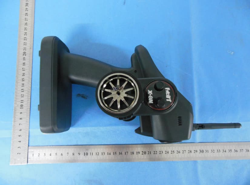
External Photographs EUT –Front View EUT – Rear View Antenna Location EUT – Side View
ID Label/Location Info
FCC ID LABEL Location FCC ID LABEL Location
ID Label/Location Info
FCC ID Label Sample 34mm 20mm
Internal Photos
Internal Photographs EUT - Open View EUT - PCB View EUT - PCB View EUT -Antenna View
RF Exposure Info
Radio Frequency Exposure Report On Behalf of SJ Incorporated FCC ID: SNL-16005500 Product Description: Gyro Receiver Graupner/SJ HoTT Model No.: GR-12+3xG+3A+Vario Supplementary Model: N/A Prepared for: SJ Incorporated 8th F,202 Dong,Chunui Techno-Park2,202,Chuni-Dong,Wonmi- Gu,Bucheon-Shi,Kyungki-Do,South Korea Prepared by: Bontek Compliance Testing Laboratory Ltd 1/F, Block East H-3, OCT Eastern Ind. Zone, Qiaocheng East Road, Nanshan, Shenzhen, China Tel: 86-755-86337020 Fax: 86-755-86337028 Report No.: BCT13HR288-1 Issue Date: August 28, 2013 Test Date: August 28~ October 22, 2013 Tested by: Reviewed by: Lion Cai Owen Yang Approved by: Kendy Wang Report No.: BCT13HR288-1 Page 2 of 5 TABLE OF CONTENTS 1 - GENERAL INFORMATION ....................................................................................................................... 3 1.1 PRODUCT DESCRIPTION FOR EQUIPMENT UNDER TEST (EUT) ........................................................................................ 3 1.2 OBJECTIVE ................................................................................................................................................................. 3 1.3 GENERAL DESCRIPTION OF TEST .................................................................................................................................. 4 1.4 HUMAN EXPOSURE ASSESSMENT RESULTS ................................................................................................................... 4 Report No.: BCT13HR288-1 Page 3 of 5 1 - GENERAL INFORMATION 1.1 Product Description for Equipment Under Test (EUT) Applicant: SJ Incorporated Address of Applicant: 8th F,202 Dong,Chunui Techno-Park2,202,Chuni-Dong,Wonmi- Gu,Bucheon-Shi,Kyungki-Do,South Korea Manufacturer 1: SJ Technology(Shenzhen)Co.,Ltd Address of manufacturer: F6, 1 Bldg, A Area, Yintianxifa Industrial Area, Xixiang Town, Baoan District Shenzhen, Guangdong Province, China Manufacturer 2: SJ Incorporated Address of Manufacturer: 8th F,202 Dong,Chunui Techno-Park2,202,Chuni-Dong,Wonmi- Gu,Bucheon-Shi,Kyungki-Do,South Korea General Description of E.U.T Items Description EUT Description: Gyro Receiver Graupner/SJ HoTT Model No.: GR-12+3xG+3A+Vario Trade Name: GRAUPNER/SJ HoTT Supplementary Model: N/A Frequency Band: 2404.056 MHz ~ 2474.025 MHz Number of Channels: 70 Type of Modulation: FHSS Antenna Gain: 1.5dBi Antenna Type: Integral Antenna Rated Voltage: Input: DC 3.6V~8.4V Adapter description: Model: N/A Input: N/A Output: N/A Remark: * The test data gathered are from the production sample provided by the manufacturer. 1.2 Objective The objective of the following report is used to demonstrate that EUT operated in a manner that ensures the public is not exposed to radio frequency energy levels in excess of the relative provisions of FCC 47CFR Part 1.1307 Report No.: BCT13HR288-1 Page 4 of 5 1.3 General Description of Test Items Description EUT Frequency band FHSS: 2.400GHz ~ 2.483GHz WLAN: 2.400GHz ~ 2.483GHz WLAN: 5.18GHz ~ 5.32GHz / 5.50GHz ~ 5.70GHz WLAN: 5.745GHz ~ 5825GHz Others: __________________________ Device category Portable (<20cm separation) Mobile (>20cm separation) Others __________________________ Exposure classification Occupational/Controlled exposure (S = 5mW/cm2) General Population/Uncontrolled exposure (S=1mW/cm 2 ) Others: __________________________ Antenna diversity Single antenna Multiple antennas: Tx diversity Rx diversity Tx/Rx diversity Max. output power 19.23dBm (0.0838W) Antenna gain (Max) 1.5dBi (Numeric gain:1.41) Evaluation applied MPE Evaluation SAR Evaluation Note: 1. The maximum output power is 19.23dBm (0.0838W) at 2474.025MHz (with 1.41 numeric antenna gain.) 2. For mobile or fixed location transmitters, no SAR consideration applied. The minimum separation generally be used is at least 20 cm, even if the calculations indicate that the MPE distance would be lesser. 1.4 Human Exposure Assessment Results Report No.: BCT13HR288-1 Page 5 of 5 EUT parameter (data from the separate report) Given Where G: numerical gain of transmitting antenna; TP: Transmitted power in watt; d: distance from the transmitting antenna in meter Max average output power in Watt (TP) 19.23dBm (0.0838W) Antenna gain (G) 1.5 dBi (Numeric gain: 1.41 Exposure classification S=1mW/cm 2 Minimum distance in meter (d) (from transmitting structure to the human body) 20cm (0.2m) Yields 2 30 3770 xPxG S d = , P=0.0838W, G=1.41, d=0.2 S=0.0235mW/cm 2 Or 30xPxG d= 3770S , S=1, P=0.0838W, G=1.41 d=0.0301m Conclusion: S=0.0235mW/cm 2 is significant lower than the General Population Exposure Power Density Limit 1mW/cm 2 or except the distance when human body proximity to the antenna is less than3.01cm then will reach the General Population Exposure Power Density Limit (For mobile or fixed location transmitters, the maximum power density is 1.0 mW / cm 2 even if the calculation indicates that the power density would be larger.)
Test Report
Test Report of FCC CFR 47 Part 15 Subpart C On Behalf of SJ Incorporated FCC ID: SNL-16005500 Product Description: Gyro Receiver Graupner/SJ HoTT Model No.: GR-12+3xG+3A+Vario Supplementary Model: N/A Prepared for: SJ Incorporated 8 th F,202 Dong,Chunui Techno-Park2,202,Chuni-Dong,Wonmi- Gu,Bucheon-Shi,Kyungki-Do,South Korea Prepared by: Bontek Compliance Testing Laboratory Co., Ltd 1/F, Block East H-3, OCT Eastern Ind. Zone, Qiaocheng East Road, Nanshan, Shenzhen, China Tel: 86-755-86337020 Fax: 86-755-86337028 Report No.: BCT13HR288E Issue Date: August 28, 2013 Test Date: August 28~ October 22, 2013 Tested by: Reviewed by: Lion Cai Owen Yang Approved by: Kendy Wang Report No.: BCT13HR288E Page 2 of 45 FCC ID: SNL-16005500 TABLE OF CONTENTS 1. GENERAL INFORMATION .................................................................................................................................... 4 1.1 PRODUCT DESCRIPTION FOR EQUIPMENT UNDER TEST (EUT) ......................................................................... 4 1.2 RELATED SUBMITTAL(S) / GRANT (S) AND TEST METHODOLOGY ....................................................................... 4 1.3 TEST FACILITY ...................................................................................................................................................... 5 2. SYSTEM TEST CONFIGURATION ...................................................................................................................... 6 2.1 EUT CONFIGURATION .......................................................................................................................................... 6 2.2 EUT EXERCISE ..................................................................................................................................................... 6 2.3 GENERAL TEST PROCEDURES ............................................................................................................................. 6 2.3.1 CHANNEL LIST .................................................................................................................................................... 7 2.4 MEASUREMENT UNCERTAINTY ............................................................................................................................. 8 2.5TEST EQUIPMENT LIST AND DETAILS .................................................................................................................... 9 3. SUMMARY OF TEST RESULTS ........................................................................................................................ 10 4. TEST OF AC POWER LINE CONDUCTED EMISSION.................................................................................. 11 4.1 APPLICABLE STANDARD ..................................................................................................................................... 11 4.2 TEST SETUP DIAGRAM ....................................................................................................................................... 11 4.3 TEST RESULT ..................................................................................................................................................... 11 5. TEST OF HOPPING CHANNEL BANDWIDTH ................................................................................................ 12 5.1 APPLICABLE STANDARD ..................................................................................................................................... 12 5.2 EUT SETUP ........................................................................................................................................................ 12 5.3 TEST EQUIPMENT LIST AND DETAILS ................................................................................................................. 12 5.4 TEST PROCEDURE .............................................................................................................................................. 12 5.5 TEST RESULT ..................................................................................................................................................... 12 6. TEST OF HOPPING CHANNEL SEPARATION ............................................................................................... 15 6.1 APPLICABLE STANDARD ..................................................................................................................................... 15 6.2 EUT SETUP ........................................................................................................................................................ 15 6.3 TEST EQUIPMENT LIST AND DETAILS ................................................................................................................. 15 6.4 TEST PROCEDURE .............................................................................................................................................. 15 6.5 TEST RESULT ..................................................................................................................................................... 15 7. TEST OF NUMBER OF HOPPING FREQUENCY ........................................................................................... 18 7.1 APPLICABLE STANDARD ..................................................................................................................................... 18 7.2 EUT SETUP ........................................................................................................................................................ 18 7.3 TEST EQUIPMENT LIST AND DETAILS ................................................................................................................. 18 7.4 TEST PROCEDURE .............................................................................................................................................. 18 7.5 TEST RESULT .........................................................…
Text truncated - open the document above for the full version.
Test Setup Photos
Test Setup Photos Radiated emission Radiated emission above 1GHz Radiated emission below 30MHz
Contact Information
Applicant
Durk Churl Gahng
Test Firm
Bontek Compliance Testing Laboratory LtdTony Wu
Technical Specifications
| # | Rule Parts | Frequency Range | Power Output |
|---|---|---|---|
| 1 | 15C | 2.40 GHz - 2.47 GHz | 83.76 mW |
Other Applications from GRAUPNER CO., LTD.
SNL-16006200
Jun 30, 20142.4 GHz Radio Control System
Equipment Class
DSS - Part 15 Spread Spectrum Transmitter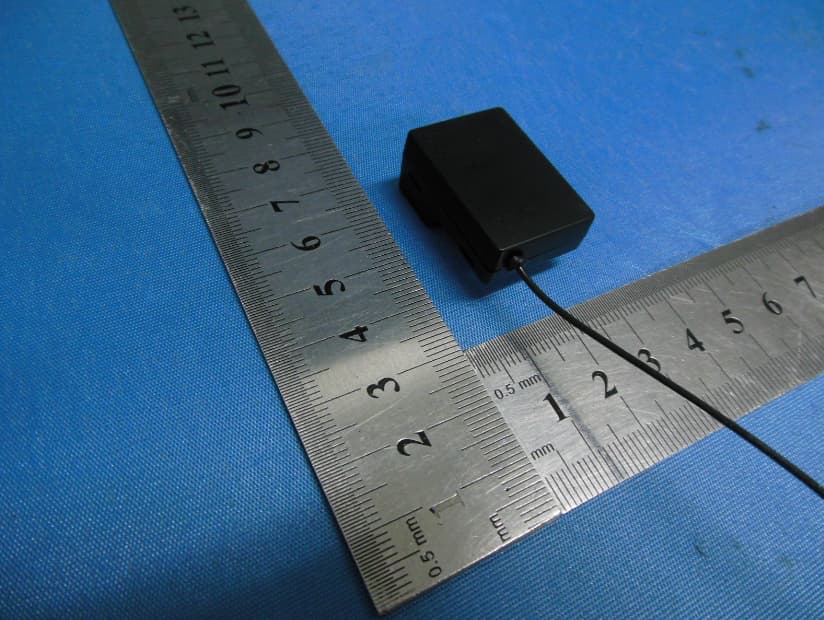
SNL-16005700
Jun 25, 20142.4 GHz Radio Control System
Equipment Class
DSS - Part 15 Spread Spectrum Transmitter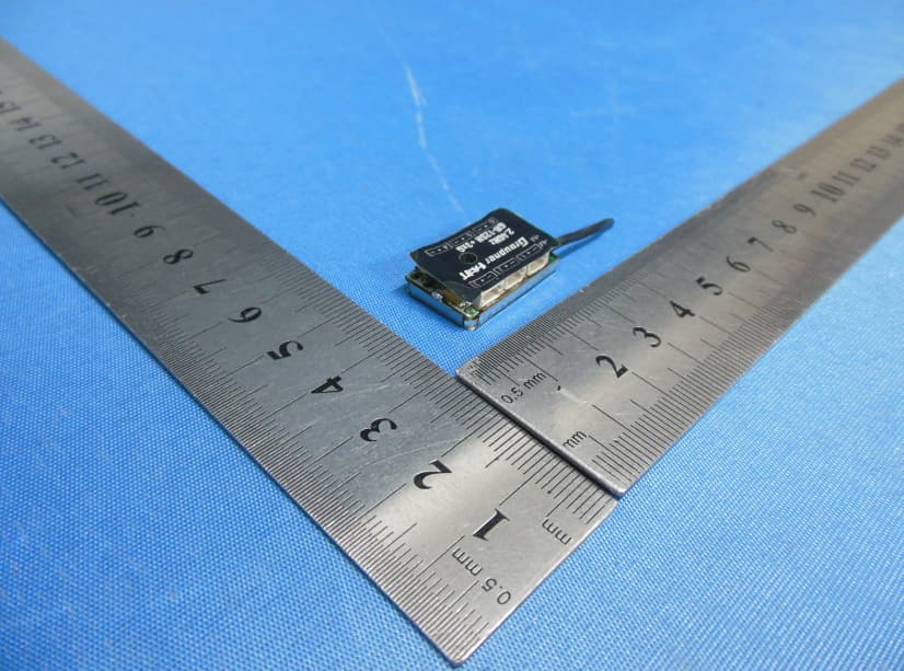
SNL-16006000
Jun 25, 20142.4 GHz Radio Control System
Equipment Class
DSS - Part 15 Spread Spectrum Transmitter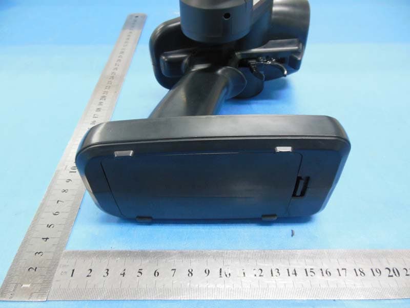
SNL-16005900
May 29, 20142.4GHz Radio Control Computer System
Equipment Class
DSS - Part 15 Spread Spectrum Transmitter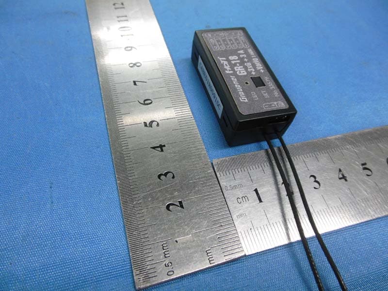
SNL-16006100
May 29, 20142.4GHz Radio Control Receiver
Equipment Class
DSS - Part 15 Spread Spectrum Transmitter