SNNDECTBASEWireless Conference Phone
Konftel AB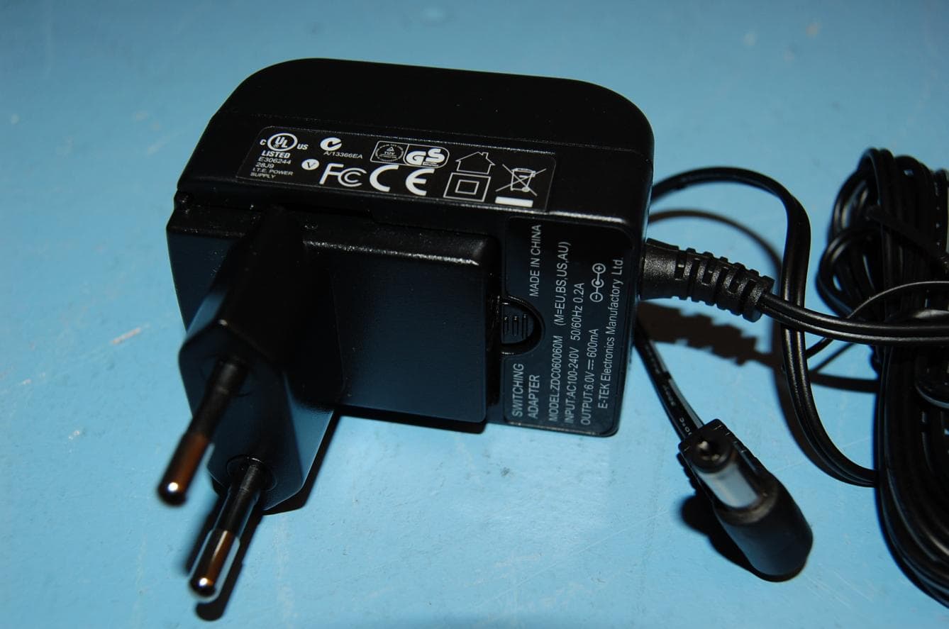
Click to zoom
Application Details
- Equipment Class
- PUB - Part 15 Unlicensed PCS Base Station
- Date of Grant
- Dec 16, 2013
- Application Purpose
- Original Equipment
- Date of Application
- Dec 16, 2013
- Equipment Note
- Wireless Conference Phone
- Frequency Range
- 1921.53600000 - 1928.44800000
- Company
- Konftel AB
- Country
- Sweden
Documents & Files
Document Text
Text extracted from the exhibit documents filed with the FCC. Open a document above to read the original.
Users Manual
Conference phones for every situation Konftel DECT Base Station ENGLISH • DEut ScH • FraNça IS • ESpañoL • S vENS ka English, Deutsch, Français, Español, Svenska 92mm 2m RegisteRing a handset (confeRence phone) A DECT-handset or a DECT conference phone has to be registered with a DECT base station before it can be used. please refer to your handset/conference phone user guide if you are unsure. If you have purchased a Konftel 300W with base station, the conference phone is already registered. set the Konftel dect base station in registration mode To be able to register a handset, the base station has to be put into registration mode. Hold down the key/LED on the base station for at least 3 seconds. The LED flashes rapidly. The base station is now in registration mode. Once registration has been completed, the LED will stop flashing. If the base station does not identify a DECT phone within 10 minutes, the registration mode will switch off automatically. Konftel DECT base station is automa- tically set into registration mode when connected to the mains. pin-code During the registration, you must enter the base station security code (PIN code) into the handset. PIN-code 0000 PARK-code Not used descRiption and connection Konftel DECT base station is GAP-compatible for analogue connec- tion to the telephone network. connection Connect the base station to a telephone jack and the mains using the power adapter as illustrated. Wall suspension The base station can be mounted on the wall. Use the screws provided as illustrated. Make sure it is securely mounted. holes for wall suspension power supplyLine connectionKey and Led screw eng Lish 92mm 2m ein handgeRät anmeLden Ein DECT Handgerät oder ein DECT Konferenztelefon müssen zuerst an einer DECT Basisstation angemeldet werden, bevor sie genutzt werden können. Bitte konsultieren sie die Bedienungs anleitung ihres handgerätes für weitere informationen. Wenn Sie das Konftel 300W im Paket mit der Konftel Basisstation erworben haben, ist das Konferenztelefon an der Basisstation bereits registriert. die Konftel dect-Basisstation in anmeldeposition stellen Um ein neues DECT Handgerät anmelden zu können muss die Basisstation in den Anmeldemodus gestellt werden. Halten Sie die Taste/Anzeigeleuchte an der Basisstation mindestens drei Sekunden lang gedrückt. Die Anzeigeleuchte blinkt dann schnell. Die Basisstation befindet sich nun in Anmelde position. Nach erfolgreicher Anmeldung hört die Anzeige auf zu blinken. Wenn die Basisstation inner halb von 10 Minuten kein DECTTelefon erkennt, wird die Anmeldeposition automatisch beendet. Die Konftel DECT Basisstation schaltet sich automatisch in den Anmeldemodus, sobald sie an der Stromversorgung angeschlossen wird. pin-code Während des Anmeldevorgangs muss der Sicherheitscode (Pin Code) der Basis station im Handgerät eingegeben werden. PIN-code 0000 PARK-code Wird nicht benötigt BeschRei Bung och anschLuss Konftel dect-Basisstation ist eine GAP-kompatible DECT- Basisstation für den analogen Anschluss an das Telefonnetz. anschluss Schließen Sie die Basisstation gemäß folgender Abbildung an eine Telefondose und mit dem Netzgerät an das Stromnetz an. Wandmontage Sie können die Basisstation auch an der Wand befestigen. Verwenden Sie hierzu die mitgelieferten Schrauben gemäß der Abbildung und prüfen Sie, ob die Station festen Halt hat. aussparung für Wandmontage stromversorgungtelefonleitungtaste und anzeigeleuchte schraube deutsch 92mm 2m enRegistRement d’un comBiné Pour pouvoir fonctionner, les combinés et téléphones de conférence DECT doivent être enregistrés sur une station de base DECT. en cas d’hésitation, voir le mode d’emploi du combiné ou du téléphone de conférence. Si vous avez acheté un Konftel 300W avec station de base, le téléphone de conférence est déjà enregistré. mettre la station de base Konftel dect en mode enregistrement Pour enregistrer un combiné, la station de base doit être mise en mode d’enregistrement. Maintenir la touche/LED de la station de base enfoncée pendant au moins 3 sec. La LED se met à clignoter rapidement. La station de base est à présent en mode enre gistrement Une fois l’enregistrement terminé, la diode cessera de clignoter. Si la station de base n’identifie pas de téléphone DECT dans un délai de 10 minutes, le mode enregistre ment se débranche automatiquement. La station de base Konftel DECT passe automatiquement en mode d’enregistrement lorsqu’elle est bran- chée sur le secteur. code pin En cours d’enregistrement, le code de sécurité (code PIN) de la station de base doit être introduit sur le combiné. Code PIN 0000 Code PARK Sans objet descRiption et connexion La station de base Konftel dect est compatible GAP pour une connexion analogique au réseau téléphonique. connexion Connecter la station de base à une prise téléphonique et la brancher au secteur à l’aide de l’adaptateur (voir illustration). suspension murale La station de base peut être fixée à un mur à l’aide des vis fournies (voir illustration). Vérifier la solidité du montage. trous pour console murale alimentationconnexion de lignetouche et diode Vis fR ançais 92mm 2m RegistRaR un micRoteLéfono Una unidad DECT o un equipo de audiocon- ferencia DECT, debe de ser registrado a una estación base DECT antes de ser usado. conslute las instrucciones de su unidad/ equipo de audioconferencia, para saber como se registra. Si es que compra un Konftel 300W con una Konftel estación base, el equipo de audioconferencia ya va estar registrado. para poner la estación base dect de Konftel en modo de registro Para que la unidad se pueda registrar, hay que poner la estación base en modo de registro. Presione y mantenga presionada la tecla/LED sobre la estación base durante al menos 3 segundos. El LED parpadea rápidamente. La estación base ya está en modo de registro. Cuando finalice la operación de registro, el piloto dejará de parpadear. Si la estación base no detecta un teléfono DECT en un plazo de 10 minutos…
Text truncated - open the document above for the full version.
Users Manual
Industry Canada warnings This product meets the applicable Industry Canada technical specifications. / Le présent matériel est conforme aux specifications techniques applicables d’Industrie Canada. The Ringer Equivalence Number (REN) is an indication of the maximum number of devices allowed to be connected to a telephone interface. The termination of an interface may consist of any combination of devices subject only to the requirement that the sum of the RENs of all the devices not exceed five. / L’indice d’équivalence de la sonnerie (IES) sert à indiquer le nombre maximal de terminaux qui peuvent être raccordés à une interface téléphonique. La terminaison d’une interface peut consister en une combinaison quelconque de dispositifs, à la seule condition que la somme d’indices d’équivalence de la sonnerie de tous les dispositifs n’excède pas cinq.This product has a Ringer Equivalence Number of 0.1 / Ce produit a une équivalence de la sonnerie Nombre de 0,1. This device complies with Industry Canada licence-exempt RSS standard(s). Operation is subject to the following two conditions: (1) this device may not cause interference, and (2) this device must accept any interference, including interference that may cause undesired operation of the device.Le présent appareil est conforme aux CNR d'Industrie Canada applicables aux appareils radio exempts de licence. L'exploitation est autorisée aux deux conditions suivantes : (1) l'appareil ne doit pas produire de brouillage, et (2) l'utilisateur de l'appareil doit accepter tout brouillage radioélectrique subi, même si le brouillage est susceptible d'en compromettre le fonctionnement. Privacy of communications may not be ensured when using this telephone. / Les communications effectuées au moyen de cet appareil ne sont pas nécessairement protégées des indiscrétions. CAN ICES-3 (B)/NMB-3(B) FCC Compliance statements This equipment complies with Part 68 of the FCC rules and the requirements adopted by the ACTA. On the bottom of this equipment is a label that contains, among other information, a product identifier in the format US: 5RWW401BDECTBASE. If requested, this number must be provided to the telephone company. A plug and jack used to connect this equipment to the premises wiring and telephone network must comply with the applicable FCC Part 68 rules and requirements adopted by the ACTA. A compliant telephone cord and modular plug is provided with this product. It is designed to be connected to a compatible modular jack that is also compliant. See installation instructions for details. The REN is used to determine the number of devices that may be connected to a telephone line. Excessive RENs on a telephone line may result in the devices not ringing in response to an incoming call. In most but not all areas, the sum of RENs should not exceed five (5.0). To be certain of the number of devices that may be connected to a line, as determined by the total RENs, contact the local telephone company. [For products approved after July 23, 2001, the REN for this product is part of the product identifier that has the format US: 5RWW401BDECTBASE. The digits represented by 01 are the REN without a decimal point (e.g., 01 is a REN of 0.1). For earlier products, the REN is separately shown on the label.] Notice: If your home has specially wired alarm equipment connected to the telephone line, ensure the installation of this unit does not disable your alarm equipment. If you have questions about what will disable alarm equipment, consult your telephone company or a qualified installer. Notice: According to telephone company reports, AC electrical surges, typically resulting from lightning strikes, are very destructive to telephone equipment connected to AC power sources. To minimize damage from these types of surges, a surge protector is recommended. An applicable certification jacks Universal Service Order Codes (USOC) for the equipment is provided in the packaging with each piece of approved terminal equipment. If trouble is experienced with this equipment (Konftel Dect Base Station), for repair or warranty information, please contact Konftel Inc., Phone: +1-(866)-606-4728. If the equipment is causing harm to the telephone network, the telephone company may request that you disconnect the equipment until the problem is resolved. If this equipment (Konftel Dect Base Station) causes harm to the telephone network, the telephone company will notify you in advance that temporary discontinuance of service may be required. But if advance notice isn’t practical, the telephone company will notify the customer as soon as possible. Also, you will be advised of your right to file a complaint with the FCC if you believe it is necessary. The telephone company may make changes in its facilities, equipment, operations or procedures that could affect the operation of the equipment. If this happens, the telephone company will provide advance notice in order for you to make necessary modifications to maintain uninterrupted service. This equipment complies with part 15 of the FCC Rules. Operation is subject to the following two conditions: (1) This device may not cause harmful interference, and (2) this device must accept interference received, including interference that may cause undesired operation. This equipment complies with the limits for a Class B digital device as specified in Part 15 of FCC Rules. These limits provide reasonable protection against radio and TV interference in a residential area. However, there is no guarantee that interference will not occur in a particular installation. If this equipment does cause harmful interference to radio or television reception, which can be determined by turning the equipment off and on, the user is encouraged to try to correct the interference by one or more of the following measures: • Reorient or relocate the receiving antenna. • Increase the distance between the equipment and the radio or TV. • Use outlets on different elec…
Text truncated - open the document above for the full version.
Cover Letter(s)
2013-06- 25 Equipment Autorisation Division Federal Communications Commission 7435 Oakland Mills Road Columbia, MD 21046 FCC ID: SNNDECTBASE Product Name: KONFTEL D ECT BASE STATION Request for Confidentiality Pursuant to Sections 0.457 and 0.459 of the commission’s rules, we hereby request that the following documents be held confidential: • Schematics • Block diagram • Operational Description These materials contain trade secrets and proprietary information and are not customarily released to the public. The public disclosure of this information might be harmful to the company and provide unjustified benefits to our competitors. Dated: June 25 2013 By: Tommy Edlund Signature Printed Title: Product Manager On behalf of : Konftel AB Telephone: +46 90 70 64 81
External Photos
- Page 1 of 2 - Photographs Order No. 235343 DECT Base station, top view DECT Base station, rear view - Page 2 of 2 - Photographs Order No. 235343 Connectors (LINE and DC input) AC adapter for use with DECT Base station
ID Label/Location Info
Made in China 49.5 mm R2.9 mm MN: Konftel DECT Base Station Item no. 840102128 Support: www.konftel.com Acta US: 5RWW401BDECTBASE 3171853 25.0 mm FCC: SNNDECTBASE IC:2408A-DECTBASE Color: Color print on white label Material: Coated matte polyester label with strong glue - recycling compatible (3M 8000) Stefan Andersson 2013-09-04 C Label: Product, DECT Base US 130241-61- 001 1(1) Release Notice Subject:Part No.: Rev.:B Doc. No.: Project Code: 91.6F409.001Release Date: Page 7 of 10 Project Name/Model No.: KT300Wx US Dect Base * Label location for machine 标签粘贴位置 PACKING STANDARD FOR KT300Wx US Dect Base 840102128 Product ID label 13007961001-B$01 PARK label 13006961001-A$01 PARK 31 77777777777 5 Product label 来料贴好 13024161001-B$01
Internal Photos
- Page 1 of 2 - Photographs Order No. 235343 Internal view, rear enclosure removed Internal view - Page 2 of 2 - Photographs Order No. 235343 PCB top side PCB rear side
RF Exposure Info
Prediction of MPE limit at a given distance S = power density P = power input to the antenna G = antenna gain R = distance Conducted output power:17.1(dBm) Tune up tolerance0.00(dB) Number of carriers1(N) 51(mW) 0.051(W) Antenna gain:1.7(dBi) Maximum antenna gain:1.48(numeric) EIRP0.076(W) ERP0.046(W) Distance:20(cm) Duty Cycle:100(%) Frequency:1920(MHz) MPE Limit:1.000(mW/cm^2) Power density:0.015(mW/cm^2) 0.15(W/m^2) Margin18.2(dB) 2 4R PG S p =
Test Report
Report No. 235343-5 Template version: B Nemko Norway Nemko AS, Instituttveien 6, P.O. Box 96 Kjeller, 2007 Kjeller, Norway TEL +47 22 96 03 30 FAX +47 22 96 05 50 EMAIL [email protected] ENTERPRISE NUMBER NO974404532 nemko.com/no Test Report Product UPCS Base Station Name and address of the applicant Konftel AB Box 268 SE-90106 Umeå, Sweden Name and address of the manufacturer Same as above Model Konftel DECT Base Station Rating / Trademark Konftel Serial number / Additional information / Tested according to FCC Part 15, subpart D Isochronous UPCS Device, 1920 – 1930 MHz Industry Canada RSS 213, Issue 2 2 GHz License-exempt Personal Communications Service Devices (LE-PCS) Order number 235343 Tested in period 2013.04.12 to 2013.09.10 Issue date 2013.11.18 Name and address of the testing laboratory Instituttveien 6 Kjeller, Norway FCC No: 994405 IC OATS: 2040D-1 TEL: (+47) 22 96 03 30 FAX: (+47) 22 96 05 50 Prepared by [Frode Sveinsen] Approved by [Thanh Tran] This report shall not be reproduced except in full without the written approval of Nemko. Opinions and interpretations expressed within this report are not part of the current accreditation. This report was originally distributed electronically with digital signatures. For more information contact Nemko. TEST REPORT FCC part 15D Report no.: 235343-5 FCC ID: SNNDECTBASE Nemko Norway, Instituttveien 6, Kjeller, Norway Page 2 (48) CONTENTS 1 INFORMATION ................................................................................................................................. 3 1.1 Tested Item........................................................................................................................................ 3 1.2 Description of Tested Device ............................................................................................................. 3 1.3 Exposure Evaluation .......................................................................................................................... 4 1.4 Test Environment .............................................................................................................................. 4 1.5 Test Engineer(s) ................................................................................................................................ 4 1.6 Test Equipment ................................................................................................................................. 4 1.7 Other Comments ............................................................................................................................... 4 2 TEST REPORT SUMMARY .............................................................................................................. 5 2.1 General .............................................................................................................................................. 5 2.2 Test Summary ................................................................................................................................... 6 3 TEST RESULTS ................................................................................................................................ 7 3.1 Power Line Conducted Emissions ..................................................................................................... 7 3.2 Coordination with fixed microwave .................................................................................................. 10 3.3 Digital Modulation Techniques ........................................................................................................ 10 3.4 Labeling Requirements ................................................................................................................... 10 3.5 Antenna Requirement...................................................................................................................... 11 3.6 Channel Frequencies ...................................................................................................................... 11 3.7 Automatic Discontinuation of Transmission .................................................................................... 12 3.8 Peak Power Output ......................................................................................................................... 13 3.9 Emission Bandwidth B ..................................................................................................................... 19 3.10 Power Spectral Density ................................................................................................................... 22 3.11 In-Band Unwanted Emissions, Conducted ...................................................................................... 25 3.12 Out-of-band Emissions, Conducted................................................................................................. 27 3.13 Carrier Frequency Stability .............................................................................................................. 31 3.14 Frame Repetition Stability ............................................................................................................... 32 3.15 Frame Period and Jitter ................................................................................................................... 32 3.16 Monitoring Threshold, Least Interfered Channel ............................................................................. 34 3.17 Threshold Monitoring Bandwidth ..................................................................................................... 36 3.18 Reaction Time and Monitoring Interval ............................................................................................ 37 3.19 Time and Spectrum Window Access Procedure ............................................................................. 39 3.20 Acknowledgements and Transmission Duration .......................................................................…
Text truncated - open the document above for the full version.
Test Report
FCC Part 15D – Compliance Information part 15d declarations_fp (2).doc 13-Mar-2013 page 1 (5) rev.2.0a EUT AND PRODUCT INFORMATION Type of Equipment UPCS (DECT 6.0) Applicant Name Konftel AB Address Box 268, S-90106, Umeå, Sweden Contact Tommy Edlund FP PP Repeater EUT Type/System FCC ID Industry Canada ID Model name Konftel DECT Base Station HW Version DVT SW Version NA Maximum Antenna Gain 3 Can the EUT be Initiating Device YES YES YES Does the EUT transmit signaling channels YES YES YES Max number of slots in use simultaneously 6 Test standard: FCC part 15D RSS-213, Issue 2 / RSS-GEN, Issue 3 Frequency Band 1921.536 – 1928.448 MHz Number of RF Channels 5 Frame Period 10 ms Max. Burst length 396uS Min. Burst Length 110uS Minimum Number of System Channels 60 Supported DECT Slot Types Full Slot Long Slot Operating Mode Simplex Duplex FCC Part 15D – Compliance Information part 15d declarations_fp (2).doc 13-Mar-2013 page 2 (5) rev.2.0a ANTENNAS Base (FP) Antenna Type Internal External 1 2 3 4 Does RX and TX use the same antenna(s)? Yes No Handset (PP) Antenna Type Internal External 1 2 Does RX and TX use the same antenna(s)? Yes No ANTENNA DIVERSITY Antenna Diversity Supported TX RX Base (FP) 1 2 3 4 Handset (PP) 1 2 VOLTAGE AND TEMPERATURE RANGES VOLTAGES FP PP Repeater Nominal Voltage 6V 14V Cut-Off Voltage (if applicable) POWER SOURCE Type Manufacturer Base or Repeater AC/DC Handset (PP) (charger) AC/DC Data Connections PSTN Others (please specify) .... FCC Part 15D – Compliance Information part 15d declarations_fp (2).doc 13-Mar-2013 page 3 (5) rev.2.0a ANCILLARY EQUIPMENT Description Type Manufacturer HOST DEVICE Description Type Manufacturer ADDITIONAL INFORMATION FCC Part 15D – Compliance Information part 15d declarations_fp (2).doc 13-Mar-2013 page 4 (5) rev.2.0a MANUFACTURERS DECLARATIONS FCC part 15.323 (c)(5) The applicant declares that the system in this application has more than 40 duplex system access channels defined, and that the system is operating in Least Interfered Channel (LIC) mode in accordance with this section. Applicant Agrees Yes No FCC part 15.323 (c)(5) No device or group of co-operating devices located within 1m of each other shall during any frame period occupy more than 6 MHz of aggregate bandwidth, or alternatively, more than one third of the time and spectrum windows defined by the system. Applicant Agrees Yes No FCC part 15.323 (c)(10) The applicant hereby declares that the system in this application does use the criteria of (c)(10) of this section. Applicant Agrees Yes No FCC part 15.323 (c)(11) The applicant hereby declares that system in this application does not use the criteria of (c)(11) of this section. Applicant Agrees Yes No FCC part 15.323 (c)(12) The provisions of (c)(10) or (c)(11) of this section shall not be used to extend the range of spectrum occupied over space or time for the purpose of denying fair access to spectrum to other devices. Applicant Agrees Yes No FCC part 15.307 (b) The Applicant is a participating member of UTAM, Inc. and will provide an affidavit from UTAM, Inc. certifying this. Confirmed By Applicant Yes No ADDITIONAL REMARKS: > DECLARED BY: 2013-12-16 Date Tommy Edlund Name (print) Signature FCC Part 15D – Compliance Information part 15d declarations_fp (2).doc 13-Mar-2013 page 5 (5) rev.2.0a About this document This document specifies the information that is needed to select the correct testcases and test procedures for testing to FCC Part 15D. The form must be completed by the applicant and submitted to Nemko before testing is started. Preparation of Equipment for Testing Note (a): Number of samples for testing The following samples are needed for FCC 15D testing: RF Conducted Tests: One sample with a 50 ohm antenna connector (preferably SMA Female). Only one antenna connector is needed for these tests even if the equipment has more than one antenna. Monitoring Tests: One sample with 50 ohm antenna connectors fitted to all antennas (preferably SMA female). Additionally we need a companion device that will work together with the EUT, the companion device must also have antenna connectors on all antennas. Radiated Tests: One sample with integral antennas. This sample will be used to measure Antenna Gain, Part 15B and Power-Line Conducted tests. Note (b): Monitoring Tests Monitoring tests are performed by establishing a connection from the handset (or the initiating device) to the base station (or the responding device). Most tests are performed by establishing connections from the initiating device to the responding device and observing which channel and/or timeslot is used. For monitoring tests we need a EUT and a Companion device that both have antenna connectors on all antennas (preferably SMA female, again). Additionally, we need access to the CLK100 signal on the Base Station, this is necessary because some of the tests require that the interferers are synced to the DECT frame. Note (c): Connection to an external power supply Means of connecting the equipment to an external power supply shall be supplied by the applicant together with the equipment to be tested. Battery operated equipment shall be supplied with the necessary batteries and chargers. All tests on battery operated equipment will be performed with batteries. Note (d): Burst Mode Most RF tests are performed with the EUT in force transmit mode. Software and necessary programming tools must be submitted to Nemko together with the test samples before start of testing. Note (e): Test-Mode (Loopback Mode) Some FCC test may also be performed in Loopback Mode with a CMD60 or similar DECT tester. If loopback mode is implemented in the EUT, the method for setting the equipment in Loopback should be submitted to Nemko together with the test samples before start of testing.
Test Setup Photos
FCC ID: SNNDECTBASE Project no.: 235343 Page 1 of 1 PHOTOS OF TEST SET-UP Power line Conducted Emissions Test
Contact Information
Applicant
Tommy Edlund
Technical Contact
Non-Technical Contact
Konftel ABSofia Karlsson
Test Firm
Nemko ASFrode Sveinsen
Technical Specifications
| # | Rule Parts | Frequency Range | Power Output |
|---|---|---|---|
| 1 | 15D | 1.92 GHz - 1.93 GHz | 55.00 mW |
Other Applications from Konftel AB
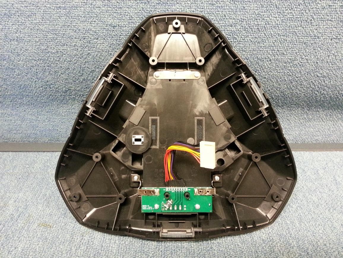
SNN300WX
Dec 16, 2013Wireless Conference Phone
Equipment Class
PUB - Part 15 Unlicensed PCS Base Station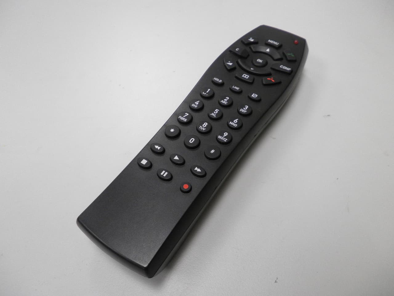
SNNRMT
Mar 08, 2012Konftel Remote Control
Equipment Class
DSC - Part 15 Security/Remote Control Transmitter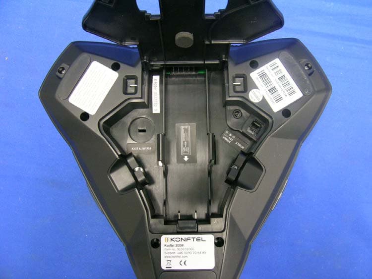
SNN1066
Apr 28, 20101.9GHz CORDLESS PHONE
Equipment Class
PUB - Part 15 Unlicensed PCS Base Station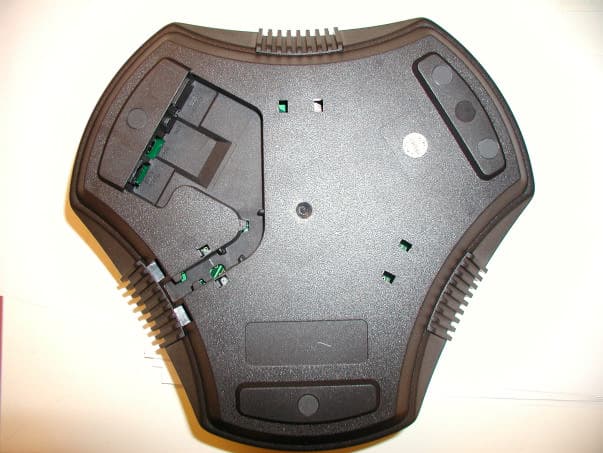
SNNC1049
Dec 27, 2004Conference Unit with Bluetooth
Equipment Class
DSS - Part 15 Spread Spectrum Transmitter