SO4YX240-PCS-CELCell Phone Signal Booster
zBoost, LLC
Click to zoom
Application Details
- Equipment Class
- PCB - PCS Licensed Transmitter
- Date of Grant
- Nov 28, 2011
- Application Purpose
- Original Equipment
- Date of Application
- Nov 28, 2011
- Equipment Note
- Cell Phone Signal Booster
- Frequency Range
- 1930.00000000 - 1990.00000000
- Company
- zBoost, LLC
- Country
- United States
Documents & Files
Document Text
Text extracted from the exhibit documents filed with the FCC. Open a document above to read the original.
Users Manual
zBoost z-Force® YX240 InstallaƟon Overview Download Product Manual at www.Wi-Ex.com Need a Signal Boost in Your Home or Office? See the full line of zBoost Signal Boosters at www.Wi-Ex.com Designed for consumers, the Wi-Ex® cell phone signal booster, z-Force, extends an in-vehicle Cell Zone. The dual band unit captures the signal outside of your car and amplifies it on the inside for a stronger “hands-free” signal. The unit incorporates a cradle and works with both 1900 MHz and 800 MHz phones – (not Nextel/iDEN, 4G or 2100 MHz). InstallaƟon is easy - this package includes everything you need. Package Contents ① zBoost Amplifier Cradle and MounƟng Adhesive ② Exterior MagneƟc Mount Antenna with 10 Ō Cable ③ 12v DC CigareƩe Power Adapter with 3 Ō Cable - OR - ④ Gooseneck Adapter Note: If your z-Force product includes the opƟonal Gooseneck Adapter (④), begin your installaƟon on Step 2. Otherwise, with the standard CLA (③), begin on Step 1. To purchase the Gooseneck Adapter, visit www.Wi-Ex.com. WARNING! Use only the provided power adapter. The use of any other power adapter or cable will harm the system and void your warranty. Before installing, please read the enƟre contents. InstallaƟon Step 1. PosiƟon zBoost Amplifier Cradle - Choose the locaƟon within your vehicle to mount the zBoost Cradle. Choose a locaƟon with a flat surface where Velcro can be applied. Avoid placing behind any metallic objects. Do not make contact with any metal surface. PosiƟon Amplifier Unit within 3 feet reach of power source. Clean the area where the mounƟng adhesive will be applied. Allow to dry. Peel backing to expose the adhesive and press onto the desired locaƟon. Remove the backing from the remaining side and press the zBoost Cradle into place. Step 2. PosiƟon Exterior MagneƟc Mount Antenna - PosiƟon Exterior MagneƟc Mount Antenna on roof of vehicle, making sure magnet is secured to metal surface. Thread the cable from exterior to the interior of the vehicle. Connect the cable connector to the Amplifier Cradle Unit. NOTE: The cord running from exterior to interior of vehicle is designed to withstand pressure when closed in door. Step 3. Connect DC Power - Connect DC Power Adapter to the zBoost Cradle using the provided cable or, if you are using a Gooseneck Adapter, by snapping the back of the cradle onto the Gooseneck. Then connect to power source within vehicle. NOTE: The leŌ side of the z-Force Cradle features a USB power connecƟon so that you can charge your cell phone while using this product. Step 4. Examine Amplifier LED - The lighted area on the zBoost Amplifier Cradle indicates the condiƟon of the system. Review LED Indicator secƟon below. NOTE: This product uses an auto-shut-off feature. When no movement is detected for 10 minutes, the unit will power down automaƟcally to avoid draining your vehicle’s baƩery and will display a slow blinking green LED. Step 5. Quick System Check - Place your cell phone in the zBoost Cradle. Check signal strength bars. Next, turn the system off (unplug unit). You should noƟce a decrease in signal bar strength. The excepƟon is if you are in an area where, with the system off, your phone is at full signal strength. Please note when you turn the system on, if your phone is receiving maximum signal strength you will not see a difference. In order for this quick test to work, you will need to test unit in a less than maximum signal strength area. © 2011 Wi-Ex, Inc. Wi-Ex.com | One Meca Way, Norcross, GA 30093 | 1-800-871-1612 DMAN-0046 Rev A FCC ID: SO4YX240-PCS-CEL IC: 5544A-YX240PCSCEL LED Status CondiƟon Solid Green Normal operaƟon Slow Blinking System has powered down aŌer sensing no Green movement for 10 minutes. Once movement resumes, system will power up. Blinking Red System is experiencing Interference. This is caused by inadequate distance between the Cradle and Exterior Antenna. Resolve by moving Exterior Antenna further back on the vehicle. Solid Red Indicates issue with power adapter. One possible cause is a loose power connecƟon. Verify that the adapter is properly secured in the socket. Another possible cause is the use of an incompaƟble power adapter. Use only the provided adapter and/or cable or risk harm to your zForce system. If you are using the adapter provided with your zForce system, please contact customer service for a replacement. LED INDICATORS PCS band Cellular band Uplink: 1850-1910 MHz Downlink: 1930-1990 MHz Uplink: 824-849 MHz Downlink: 869-894 MHz Band supported up to 35dBup to 43dB A, D, B, E, F, C A, B, A’, B’ CDMA, GSM, GPRS, EDGE, EVDO, 1xRTT, UMTS, HSPA, 3G Output Power Networks Power Source FCC Parts 15 & 24 (PCS), Parts 15 & 22 (CEL), Industry Canada Base Unit Size and Weight OperaƟng CondiƟons Frequency System Gain System CerƟficaƟons 4.4” x 3.0” x 1.9” – 20 oz. 5 - 50°C (40 - 122° F) This product uses patented technology to protect the carrier network (US 7,706,744); addiƟonal patents pending 12V adapter DL: +0dBm UL: +21dBm zBOOST ZFORCE YX240 TECHNICAL SPECIFICATIONS OROROROR ④ ③②① ④④ ③ ③ ② ① ③ ③③ ④④④ Gooseneck (optional) ① Power Adapter (CLA) zForce Cradle Amplifier Exterior Magnetic Mount Antenna USB Power ConnecƟon 12 v Adapter LED Indicator Gooseneck Adapter Exterior Antenna zBoost Amplifier Cradle ④ ③ ② ① InstallaƟon Guide Model Number: YX240 Technical Support For technical support, warranty issues or return authorizaƟon, contact Wi-Ex Support between the hours of 8:30 AM and 5:30 PM EST at 1-800-871-1612, email [email protected] or visit www.Wi-Ex.com. Before calling, locate the serial number on the amplifier unit. The serial number is required for technical support or establish a return authorizaƟon. FCC InformaƟon FCC ID: SO4YX240-PCS-CEL Warning: Changes or modificaƟons to this device not expressly approved by Wi-Ex could void the user’s authority to operate the equipment. Note: This equipment has been tested and found to comply with the limits for a Class B digital device, pursuant to Part 15 of the FCC Rules. These lim…
Text truncated - open the document above for the full version.
External Photos
Wi-Ex, Inc. FCC ID: SO4YX240-PCS-CEL Report Number: R1110172-2224 Page 75 of 80 FCC Part 22H/24E Test Report 14 EXHIBIT C – EUT PHOTOGRAPHS 14.1 EUT - Top View 14.2 EUT - Bottom View Wi-Ex, Inc. FCC ID: SO4YX240-PCS-CEL Report Number: R1110172-2224 Page 76 of 80 FCC Part 22H/24E Test Report 14.3 EUT - Side View (1) 14.4 EUT - Side View (2) Wi-Ex, Inc. FCC ID: SO4YX240-PCS-CEL Report Number: R1110172-2224 Page 77 of 80 FCC Part 22H/24E Test Report 14.5 EUT - Side View (3) 14.6 EUT – Side View (4)
ID Label/Location Info
FCC ID/IC Label
Internal Photos
Wi-Ex, Inc. FCC ID: SO4YX240-PCS-CEL Report Number: R1110172-2224 Page 78 of 80 FCC Part 22H/24E Test Report 14.7 EUT – Cover off View 14.8 EUT – PCB Board Assembly Top View Wi-Ex, Inc. FCC ID: SO4YX240-PCS-CEL Report Number: R1110172-2224 Page 79 of 80 FCC Part 22H/24E Test Report 14.9 EUT – PCB Board Assembly Bottom View (1) 14.10 EUT – PCB Board Assembly Bottom View (2) Wi-Ex, Inc. FCC ID: SO4YX240-PCS-CEL Report Number: R1110172-2224 Page 80 of 80 FCC Part 22H/24E Test Report 14.11 EUT – AC/DC Adapter View 14.12 EUT – USB Power Board View --- END OF REPORT ---
RF Exposure Info
Wi-Ex, Inc. FCC ID: SO4YX240-PCS-CEL Report Number: R1110172-2224 Page 70 of 80 FCC Part 22H/24E Test Report 11 FCC §1.1307(b)(1) & §2.1091 - RF EXPOSURE INFORMATION 11.1 Applicable Standard According to FCC §1.1310 and §2.1091 (Mobile Devices) RF exposure is calculated. Limits for General Population/Uncontrolled Exposure Frequency Range (MHz) Electric Field Strength (V/m) Magnetic Field Strength (A/m) Power Density (mW/cm 2 ) Averaging Time (minute) Limits for General Population/Uncontrolled Exposure 0.3-1.34 614 1.63 *(100) 30 1.34-30 824/f 2.19/f *(180/f 2 ) 30 30-300 27.5 0.073 0.2 30 300-1500 / / f/1500 30 1500-100,000 / / 1.0 30 Note: f = frequency in MHz * = Plane-wave equivalent power density 11.2 MPE Prediction Predication of MPE limit at a given distance, Equation from OET Bulletin 65, Edition 97-01 S = PG/4πR² Where: S = power density P = power input to antenna G = power gain of the antenna in the direction of interest relative to an isotropic radiator R = distance to the center of radiation of the antenna Cellular Band Uplink: Maximum peak output power at antenna input terminal (dBm):22.43 Maximum peak output power at antenna input terminal (mW):174.98 Prediction distance (cm):20 Prediction frequency (MHz):836.6 Antenna Gain, typical (dBi):2.0 Cable Loss (dB):3.0 Power density at predication frequency and distance (mW/cm 2 ):0.0277 MPE limit for uncontrolled exposure at predication frequency (mW/cm 2 ):0.5577 Wi-Ex, Inc. FCC ID: SO4YX240-PCS-CEL Report Number: R1110172-2224 Page 71 of 80 FCC Part 22H/24E Test Report Cellular Band Downlink: Maximum peak output power at antenna input terminal (dBm):0.93 Maximum peak output power at antenna input terminal (mW):1.24 Prediction distance (cm):20 Prediction frequency (MHz):891.6 Antenna Gain, typical (dBi):0 Cable Loss (dB):3.0 Power density at predication frequency and distance (mW/cm 2 ):0.000124 MPE limit for uncontrolled exposure at predication frequency (mW/cm 2 ):0.5944 PCS Band Uplink: Maximum peak output power at antenna input terminal (dBm):22.80 Maximum peak output power at antenna input terminal (mW):190.55 Prediction distance (cm):20 Prediction frequency (MHz):1909.8 Antenna Gain, typical (dBi):2.0 Cable Loss (dB):5.0 Power density at predication frequency and distance (mW/cm 2 ):0.019 MPE limit for uncontrolled exposure at predication frequency (mW/cm 2 ):1.0 PCS Band Downlink: Maximum peak output power at antenna input terminal (dBm):0.75 Maximum peak output power at antenna input terminal (mW):1.189 Prediction distance (cm):20 Prediction frequency (MHz):1989.8 Antenna Gain, typical (dBi):0 Cable Loss (dB):5.0 Power density at predication frequency and distance (mW/cm 2 ):0.0000748 MPE limit for uncontrolled exposure at predication frequency (mW/cm 2 ):1.0 Results For Uplink, the highest power density level at 20 cm is below the MPE uncontrolled exposure limit. For Downlink; the highest power density level at 20 cm is below the MPE uncontrolled exposure limit.
Test Report
Note: This test report is prepared for the customer shown above and for the device described herein. It may not be duplicated or used in part without prior written consent from Bay Area Compliance Laboratories Corp. This report must not be used by the customer to claim product certification, approval, or endorsement by NVLAP*, NIST, or any agency of the Federal Government. * This report may contain data that are not covered by the NVLAP accreditation and are marked with an asterisk “*” (Rev.2) FCC PART 22H, 24E TEST AND MEASUREMENT REPORT For Wi-Ex Inc. One Meca Way, Norcross, GA 30093, USA FCC ID: SO4YX240-PCS-CEL Report Type: Original Report Product Type: Bi Directional Amplifier Test Engineer: Quinn Jiang Report Number: R1110172-2224 Report Date: 2011-11-21 Reviewed By: Victor Zhang EMC/RF Lead Prepared By: (84) Bay Area Compliance Laboratories Corp. 1274 Anvilwood Ave., Sunnyvale, CA 94089, USA Tel: (408) 732-9162 Fax: (408) 732 9164 Wi-Ex, Inc. FCC ID: SO4YX240-PCS-CEL Report Number: R1110172-2224 Page 2 of 80 FCC Part 22H/24E Test Report TABLE OF CONTENTS 1 GENERAL INFORMATION ............................................................................................................................... 5 1.1 PRODUCT DESCRIPTION FOR EQUIPMENT UNDER TEST (EUT)........................................................................... 5 1.2 MECHANICAL DESCRIPTION.............................................................................................................................. 5 1.3 OBJECTIVE......................................................................................................................................................... 5 1.4 RELATED SUBMITTAL(S)/GRANT(S)................................................................................................................... 5 1.5 TEST METHODOLOGY........................................................................................................................................ 5 1.6 MEASUREMENT UNCERTAINTY.......................................................................................................................... 6 1.7 TEST FACILITY................................................................................................................................................... 6 2 SYSTEM TEST CONFIGURATION .................................................................................................................. 7 2.1 JUSTIFICATION................................................................................................................................................... 7 2.2 EUT EXERCISE SOFTWARE................................................................................................................................7 2.3 EQUIPMENT MODIFICATIONS............................................................................................................................. 7 2.4 POWER SUPPLY AND LINE FILTERS.................................................................................................................... 7 2.5 INTERNAL CONFIGURATION...............................................................................................................................7 2.6 LOCAL SUPPORT EQUIPMENT LIST AND DETAILS.............................................................................................. 7 2.7 INTERFACE PORTS AND CABLING...................................................................................................................... 8 3 SUMMARY OF TEST RESULTS........................................................................................................................ 9 4 FCC §2.1046, §22.913(A) & §24.232 – RF OUTPUT POWER ........................................................................ 10 4.1 APPLICABLE STANDARD.................................................................................................................................. 10 4.2 TEST PROCEDURE............................................................................................................................................ 10 4.3 TEST EQUIPMENT LIST AND DETAILS.............................................................................................................. 10 4.4 TEST ENVIRONMENTAL CONDITIONS............................................................................................................... 10 4.5 TEST RESULTS................................................................................................................................................. 11 5 FCC §2.1047 - MODULATION CHARACTERISTIC..................................................................................... 13 5.1 APPLICABLE STANDARD.................................................................................................................................. 13 5.2 TEST RESULT................................................................................................................................................... 13 6 FCC §2.1049, §22.917 & §24.238 - OCCUPIED BANDWIDTH...................................................................... 14 6.1 APPLICABLE STANDARD.................................................................................................................................. 14 6.2 TEST PROCEDURE............................................................................................................................................ 14 6.3 TEST EQUIPMENT LIST AND DETAILS.............................................................................................................. 14 6.4 TEST ENVIRONMENTAL CONDITIONS............................................................................................................... 14 6.5 TEST RESULTS................................................................................................................................................. 15 7 FCC §2.1053, §22.917 & §24.238 - SPURIOUS…
Text truncated - open the document above for the full version.
Test Setup Photos
Wi-Ex, Inc. FCC ID: SO4YX240-PCS-CEL Report Number: R1110172-2224 Page 73 of 80 FCC Part 22H/24E Test Report 13 EXHIBIT B - TEST SETUP PHOTOGRAPHS 13.1 Radiated Emissions - Front View 13.2 Radiated Emissions - Rear View (Below 1 GHz) Wi-Ex, Inc. FCC ID: SO4YX240-PCS-CEL Report Number: R1110172-2224 Page 74 of 80 FCC Part 22H/24E Test Report 13.3 Radiated Emissions - Rear View (Above 1 GHz)
Contact Information
Applicant
Scott Terry(VP of Engineering)
Test Firm
Bay Area Compliance LaboratoryJohn Chan
Technical Specifications
| # | Rule Parts | Frequency Range | Power Output | Emission | Tolerance |
|---|---|---|---|---|---|
| 12 | 24E | 1.93 GHz - 1.99 GHz | 1.00 mW | F9W | Amp |
Other Applications from zBoost, LLC

SO4ZB570-PCS-CEL
Mar 19, 2014Part 20 Wideband Consumer Booster
Equipment Class
B2W - Part 20 Wideband Consumer Booster (CMRS)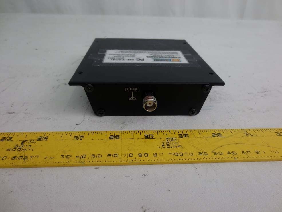
SO4YX741-PCS-CEL
Mar 18, 2014Industrial Booster
Equipment Class
B2I - Part 20 Industrial Booster (CMRS)
SO4YX550-AWS-ALTE
Feb 14, 20134G Cellular Signal Amplifier
Equipment Class
AMP - Amplifier
SO4YX550-AWS-VLTE
Jul 16, 20124G Cellular Signal Amplifier
Equipment Class
TNB - Licensed Non-Broadcast Station Transmitter
SO4YX545-PCS-CEL2
May 23, 2012Cellular Signal Booster
Equipment Class
PCB - PCS Licensed Transmitter