SO4YX500-CELCellular Bi-Directional Booster
zBoost, LLC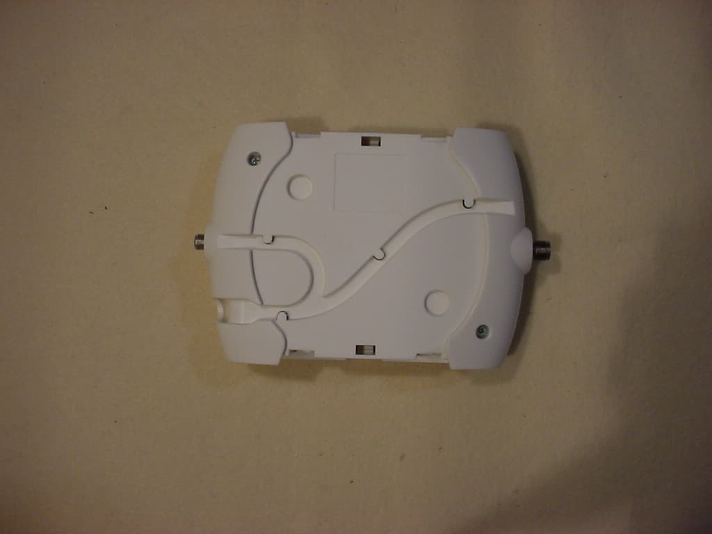
Click to zoom
Application Details
- Equipment Class
- TNB - Licensed Non-Broadcast Station Transmitter
- Date of Grant
- Nov 07, 2005
- Application Purpose
- Original Equipment
- Date of Application
- Nov 07, 2005
- Equipment Note
- Cellular Bi-Directional Booster
- Frequency Range
- 869.00000000 - 894.00000000
- Company
- zBoost, LLC
- Country
- United States
Documents & Files
Document Text
Text extracted from the exhibit documents filed with the FCC. Open a document above to read the original.
Users Manual
5015 B.U. Bowman Drive Buford, GA 30518 USA Voice: 770-831-8048 Fax: 770-831-8598 FCC Part 22 Transmitter Certification Test Report FCC ID: SO4YX500-CEL FCC Rule Part: CFR 47 Part 22 Subpart H ACS Report Number: 05-0343-22H Manufacturer: Wireless Extenders Equipment Type: Cellular Band Bi-Directional Booster Model: YX500-CEL Installation Guide Rev. A YX500-CEL Installation Guide Wireless Extenders Rev. A YX500-CEL Installation Guide Copyright Notice This manual is copyrighted. All rights reserved. This manual, whole or in part, may not be copied, photocopied, reproduced, translated, or reduced to any electronic medium or machine-readable form for distribution. This manual, whole or in part, may not be modified without prior consent, in writing, from Wireless Extenders. Copyright © 2005 by Wireless Extenders, Inc. 330 Research Court Suite 250, Norcross, GA 30092, U.S.A. Trademarks Wireless Extenders, the Wireless Extenders logo, and Wireless Where You Want It are registered trademarks of Wireless Extenders, Inc. iDEN is a registered trademark of Motorola. Nextel is a registered trademark of Nextel Communications Corp. FCC Information FCC ID: SO4YX500-CEL This equipment has been tested and found to comply with the limits for a Class B digital device, pursuant to Part 15 of the FCC Rules. These limits are designed to provide reasonable protection against harmful interference in the residential installation. This equipment generates, uses and can radiate radio frequency energy and, if not installed and used in accordance with the instructions, may cause harmful interference to radio communications. However, there is no guarantee that interference will not occur in a particular installation. If this equipment does cause harmful interference to radio or television reception, which can be determined by turning the equipment off and on, the user is encouraged to try to correct the interference by one or more of the following measures: • Reorient or relocate the receiving antenna. • Increase the separation between the equipment and receiver. • Connect the equipment into an outlet on a circuit different from that to which the receiver is connected. • Consult the dealer or a professional installer for help. Industry Canada Regulations Canada IC: 5544A-YX500CEL This Class B digital apparatus meets all requirements of the Canadian Interference Causing Equipment Regulations. Operation is subject to the following two conditions: (1) this device may not cause harmful interference, and (2) this device must accept any interference received, including interference that may cause undesired operation. Cet appareillage numérique de la classe [B] répond à toutes les exigences de l'interférence canadienne causant des règlements d'équipement. L'opération est sujette aux deux conditions suivantes: (1) ce dispositif peut ne pas causer l'interférence nocive, et (2) ce dispositif doit accepter n'importe quelle interférence reçue, y compris l'interférence qui peut causer l'opération peu désirée. Wireless Extenders i YX500-CEL Installation Guide Rev. A Read First Before Installing the YX500-CEL YX500-CEL For Cell Phones Operating on Cellular 800MHZ Frequencies Only Before unpacking this box, verify that your phone operates on Cellular 800MHz frequencies. The YX500-CEL will enhance your in-building coverage for local provider networks operating at the 800MHz (Cellular) frequency. To verify that your phone uses Cellular 800MHz frequencies, please follow these four simple steps: 1) Unpack the Base Unit and the Base Unit power supply only. 2) Connect the power supply to the Base Unit and plug it into an outlet. All of the lights will flash for several seconds. The Power light should now be solid green. 3) While standing about 1 foot away from the Base Unit, turn on your cell phone or make a call. If the Signal light begins flashing green, you can proceed with the installation of the YX500. If it flashes red, move your phone away from the Base Unit (typical for GSM). 4) If the Signal light does not flash green, try to place another call with your cell phone directly touching the YX500 (typical for CDMA). If the Signal light still does not flash green, your cell phone may not be compatible with the YX500- CEL. Contact Wireless Extenders technical support at 1-800-871-1612 for further assistance. Note: The YX500 is fully automatic. The Install, Signal, and Power lights on the Base Unit are not buttons. There are no buttons to press on the Base Unit. ii Wireless Extenders YX500-CEL Installation Guide Safety and Product Warranty Information Safety Guidelines Please adhere to the following safety guidelines during the installation of the YX500-CEL. 1) In accordance with FCC requirements of human exposure to radiofrequency fields, the radiating element (antenna) shall be installed such that a minimum separation distance of 8 inches (20cm) is maintained between the radiating element and the user and/or general population. 2) If a ladder is required to install the YX500, make sure that the ladder feet are on a flat surface and the ladder is securely fixed. It is highly recommended that you have someone assist you while you are on the ladder. 3) You should always wear proper eye protection when working with power tools. 4) Keep all plastic bags away from children to avoid suffocation hazard. 5) Before drilling make sure you know where existing electrical wiring is so as not to hit the wiring, which could cause an electrical shock and severe the wiring. Limited Liability In no event shall Wireless Extenders be liable for any direct, indirect, special, punitive, incidental, exemplary or consequential damages, or any damages, whether in an action under contract, negligence, or any other theory, arising out of or in connection with the installation of, use of, inability to use, or performance of the information, services, products, and materials available from this manual. These limitations shall apply notwithstanding any failure of es…
Text truncated - open the document above for the full version.
Cover Letter(s)
Wireless Where You Want It TM Federal Communications Commission Date: 09/26/05 Equipment Authorization Branch 7435 Oakland Mills Road Columbia, MD 21046 Gentlemen: Wireless Extenders respectfully requests confidentiality of certain materials provided with the submission of the YX500-CEL under FCC ID: SO4YX500-CEL in accordance with FCC Regulations 0.459. The confidentiality request applies to the schematics, parts lists, and block diagrams contained in this filing. Pursuant to DA 04-1705 June 15, 2004 of the Commission’s public notice, we also request temporary confidential treatment of the internal photos. We are working on new patents and we believe our competitors (especially foreign) will be able to copy some of our technology much more quickly if they have access to internal photos. The YX500-CEL has been developed at considerable effort and expense by Wireless Extenders. These items are considered as highly sensitive and therefore public access to the proprietary material could possibly result in duplication of equipment that could severely damage the company's business advantage. I appreciate your assistance in this matter. Sincerely, Michael W Rodgers Signature:_________________________________ Date: November 7, 2005 Title: VP of Engineering 330 Research Court Suite 250 Norcross, Georgia 30092 Fax: 770-239-5473
External Photos
5015 B.U. Bowman Drive Buford, GA 30518 USA Voice: 770-831-8048 Fax: 770-831-8598 FCC Part 22 Transmitter Certification Test Report FCC ID: SO4YX500-CEL FCC Rule Part: CFR 47 Part 22 Subpart H ACS Report Number: 05-0343-22H Manufacturer: Wireless Extenders Equipment Type: Cellular Band Bi-Directional Booster Model: YX500-CEL External Photographs Model: YX500-CEL Advanced Compliance Solutions FCC ID: SO4YX500-CEL 5015 B.U. Bowman Drive Buford, GA 30518 USA Voice: 770-831-8048 Fax: 770-831-8598 Figure 1: EUT Side View Model: YX500-CEL Advanced Compliance Solutions FCC ID: SO4YX500-CEL 5015 B.U. Bowman Drive Buford, GA 30518 USA Voice: 770-831-8048 Fax: 770-831-8598 Figure 2: EUT Top View Model: YX500-CEL Advanced Compliance Solutions FCC ID: SO4YX500-CEL 5015 B.U. Bowman Drive Buford, GA 30518 USA Voice: 770-831-8048 Fax: 770-831-8598 Figure 3: EUT Bottom View Model: YX500-CEL Advanced Compliance Solutions FCC ID: SO4YX500-CEL 5015 B.U. Bowman Drive Buford, GA 30518 USA Voice: 770-831-8048 Fax: 770-831-8598 Figure 4: EUT Bottom View with Mounting Hardware Model: YX500-CEL Advanced Compliance Solutions FCC ID: SO4YX500-CEL 5015 B.U. Bowman Drive Buford, GA 30518 USA Voice: 770-831-8048 Fax: 770-831-8598 Figure 5: EUT Front View Model: YX500-CEL Advanced Compliance Solutions FCC ID: SO4YX500-CEL 5015 B.U. Bowman Drive Buford, GA 30518 USA Voice: 770-831-8048 Fax: 770-831-8598 Figure 6: EUT Rear View
ID Label/Location Info
5015 B.U. Bowman Drive Buford, GA 30518 USA Voice: 770-831-8048 Fax: 770-831-8598 FCC Part 22 Transmitter Certification Test Report FCC ID: SO4YX500-CEL FCC Rule Part: CFR 47 Part 22 Subpart H ACS Report Number: 05-0343-22H Manufacturer: Wireless Extenders Equipment Type: Cellular Band Bi-Directional Booster Model: YX500-CEL Label Information 2.00" 3.00" SPECTRAL RESPONSE, INC. Electronic Manufacturing Services Wireless Extenders LEDLabel, CEL Date: 9/30/05 SRI Part #:MAB0018AWX RevAPRELIMINARY SRI Part Desc: WX FC/LED LBLDLAB-0018 Wireless Extenders Part # DLAB-0018 Material:0.002 thick white semi-gloss polyester with permanent adhesive 3 ì Core size 0.062 R (standard) +/- 0.010î +/- 0.010î I S O 9 0 0 1 : 2 0 0 0 I S O 1 3 4 8 5 : 2 0 0 3 A 5 6 9 2 Page 1 of 2 SPECTRAL RESPONSE, INC. Electronic Manufacturing Services Wireless Extenders LED Label, CEL SRI Part #:MAB0018AWX RevA SRI Part Desc: WX FC/LED LBLDLAB-0018 Wireless Extenders Part # DLAB-018 Page 2 of 2 Artwork See manual for more detail LED (GREEN) POWERAPPLIED (OFF) INSTALLED CORRECTLY (RED) INSTALLATION ERROR (FLASHING GREEN) GOOD (FLASHING RED) CAUTION (RED) SHUT DOWN POWER INSTALL SIGNAL FCC ID: SO4YX500-CELIC ID:5544A-YX500CEL This device complies with part 15 of the FCC Rules. Operation is subject to the following two conditions: (1)This device may not cause harmful interference, and (2) this device must accept any interference received, including interference that may cause undesired operation. This Class B digital apparatus meets all requirements of the Canadian Interference Causing Equipment Regulations. Operation is subject to the following two conditions: (1) this device may not cause harmful interference, and (2) this device must accept any interference received, including interference that may cause undesired operation. Cet appareillage numÈrique de la classe B rÈpond ‡ toutes les exigences de l'interfÈrence canadienne causant des rËglements d'Èquipement. L'opÈration est sujette aux deux conditions suivantes: (1) ce dispositif peut ne pas causer l'interfÈrence nocive, et (2) ce dispositif doit accepter n'importe quelle interfÈrence reÁue, y compris l'interfÈrence qui peut causer l'opÈration peu dÈsirÈe. Figure 1. Label Location Label Location
Internal Photos
5015 B.U. Bowman Drive Buford, GA 30518 USA Voice: 770-831-8048 Fax: 770-831-8598 FCC Part 22 Transmitter Certification Test Report FCC ID: SO4YX500-CEL FCC Rule Part: CFR 47 Part 22 Subpart H ACS Report Number: 05-0343-22H Manufacturer: Wireless Extenders Equipment Type: Cellular Band Bi-Directional Booster Model: YX500-CEL Internal Photographs Model: YX500-CEL Advanced Compliance Solutions FCC ID: SO4YX500-CEL 5015 B.U. Bowman Drive Buford, GA 30518 USA Voice: 770-831-8048 Fax: 770-831-8598 Figure 1: EUT PCB Top View Model: YX500-CEL Advanced Compliance Solutions FCC ID: SO4YX500-CEL 5015 B.U. Bowman Drive Buford, GA 30518 USA Voice: 770-831-8048 Fax: 770-831-8598 Figure 2: EUT PCB Bottom View
Operational Description
5015 B.U. Bowman Drive Buford, GA 30518 USA Voice: 770-831-8048 Fax: 770-831-8598 FCC Part 22 Transmitter Certification Test Report FCC ID: SO4YX500-CEL FCC Rule Part: CFR 47 Part 22 Subpart H ACS Report Number: 05-0343-22H Manufacturer: Wireless Extenders Equipment Type: Cellular Band Bi-Directional Booster Model: YX500-CEL Theory of Operation Theory of Operation: As a BDA, the YX500-CEL amplifies both the downlink (tower to phone, 869- 894 MHz) and the uplink (phone to tower, 824-849 MHz). The outdoor network signal (downlink) is captured by the Signal Antenna, transferred through the coaxial cable, and arrives at the Base Unit. Inside the Base Unit, a duplexer diverts the downlink signal, amplifies the full band, isolates it from the uplink, and detects the power level. The downlink band is then recombined with another duplexer where the Base Unit Antenna sends the signal inside the home or office. The downlink final amplifier operates class A at 3.6V and 50mA. Similarly, the cell phone signal (uplink) is captured by the Base Unit Antenna and, inside the Base Unit, a duplexer diverts the uplink signal, amplifies the full band, isolates it from the downlink, and detects the power level. The uplink band is then recombined with another duplexer where it exits the Base Unit, is transferred through the coaxial cable to the Signal Antenna which sends the signal to the outdoor network. The uplink PA operates class AB at 3.6V and 200mA – 800mA. The detected power levels are monitored by a microcontroller. The microcontroller limits the maximum output power to keep the amplifiers linear without interfering with the network power control. Patent pending circuitry and algorithms also detect low-level self-oscillation and either corrects it or shuts down while alerting the user with LED outputs.
Parts List/Tune Up Info
5015 B.U. Bowman Drive Buford, GA 30518 USA Voice: 770-831-8048 Fax: 770-831-8598 FCC Part 22 Transmitter Certification Test Report FCC ID: SO4YX500-CEL FCC Rule Part: CFR 47 Part 22 Subpart H ACS Report Number: 05-0343-22H Manufacturer: Wireless Extenders Equipment Type: Cellular Band Bi-Directional Booster Model: YX500-CEL Tune-up Procedure This document contains proprietary information and is loaned in confidence subject to return upon demand on the express condition that it will not be used in any way not authorized by Wireless Extenders. Type Document Number Rev Page 1 of 6 1 YX500-CEL Cellular BDA Tuning Procedure WIRELESS EXTENDERS, INC. 330 Research Court Suite 250 Norcross, GA 30092 Wireless Extenders, Inc. 2005 All rights reserved YX500-CEL Tuning Procedure Company Document Number Rev Confidential Page 2 of 6 1 Revision History Rev/Ver Description Date Changed By Wireless Extenders, Inc. 2005 All rights reserved YX500-CEL Tuning Procedure Company Document Number Rev Confidential Page 3 of 6 1 1. Purpose The purpose of this document is to outline a tuning procedure for defining maximum RF output power on Up link path and down link path. Wireless Extenders, Inc. 2005 All rights reserved YX500-CEL Tuning Procedure Company Document Number Rev Confidential Page 4 of 6 1 2. RF Power Tuning Procedure 2.1. UUT Functional Test 2.1.1. DC Test Test UUT for proper DC voltage and current. 2.1.2. Verify Uplink P1dB Up link P1dB measurement is made to verify if maximum RF output power is acceptable. 2.1.3. Verify Downlink P1dB Down link P1dB measurement is made to verify if maximum RF output power is acceptable. 2.2. RF Output Power Level Calibration Sequence 2.2.1. Downlink RF Output Power Level Calibration 2.2.1.1. Measure Downlink –10dBm level measure the Downlink RF Power Calibration at -10dBm output power level. Record the detected voltage level. 2.2.1.2. Measure Downlink –5dBm level measure the Downlink RF Power Calibration at -5dBm output power level. Record the detected voltage level. 2.2.1.3. Measure Downlink 0dBm level measure the Downlink RF Power Calibration at 0dBm output power level. Record the detected voltage level. 2.2.1.4. Measure Downlink 5dBm level measure the Downlink RF Power Calibration at 5dBm output power level. Record the detected voltage level. 2.2.1.5. Measure Downlink 10dBm level measure the Downlink RF Power Calibration at 10dBm output power level. Record the detected voltage level. 2.2.1.6 Measure Downlink 15dBm level measure the Downlink RF Power Calibration at 15dBm output power level. Record the detected voltage level. Wireless Extenders, Inc. 2005 All rights reserved YX500-CEL Tuning Procedure Company Document Number Rev Confidential Page 5 of 6 1 2.2.1.7 Measure Downlink 18dBm level measure the Downlink RF Power Calibration at 18dBm output power level. Record the detected voltage level. 2.2.1.6. Store Downlink maximum Level Set maximum RF output power on the down link path by interpolating the detected voltage level curve. 2.2.2. Uplink RF Power Output Level CalibrationMake Loop Decision 2.2.2.1. Measure Uplink –10dBm level measure the uplink RF Power Calibration at -10dBm output power level. Record the detected voltage level. 2.2.2.2. Measure Uplink –5dBm level measure the uplink RF Power Calibration at -5dBm output power level. Record the detected voltage level. 2.2.2.3. Measure Uplink 0dBm level measure the uplink RF Power Calibration at 0dBm output power level. Record the detected voltage level. 2.2.2.4. Measure Uplink 5dBm level measure the uplink RF Power Calibration at 5dBm output power level. Record the detected voltage level. 2.2.2.5. Measure Uplink 10dBm level measure the uplink RF Power Calibration at –d10Bm output power level. Record the detected voltage level. 2.2.2.6. Measure Uplink 15dBm level measure the uplink RF Power Calibration at 15dBm output power level. Record the detected voltage level. 2.2.2.7. Measure Uplink 20dBm level measure the uplink RF Power Calibration at 20dBm output power level. Record the detected voltage level. 2.2.2.8. Measure Uplink 25dBm level measure the uplink RF Power Calibration at 25dBm output power level. Record the detected voltage level. Wireless Extenders, Inc. 2005 All rights reserved YX500-CEL Tuning Procedure Company Document Number Rev Confidential Page 6 of 6 1 2.2.2.9. Measure Uplink 30dBm level measure the uplink RF Power Calibration at 30dBm output power level. Record the detected voltage level. 2.2.2.10. Store Uplink Maximum output power level Set maximum RF output power on the up link path by interpolating the detected voltage level curve.
RF Exposure Info
5015 B.U. Bowman Drive Buford, GA 30518 USA Voice: 770-831-8048 Fax: 770-831-8598 FCC Part 22 Transmitter Certification Test Report FCC ID: SO4YX500-CEL FCC Rule Part: CFR 47 Part 22 Subpart H ACS Report Number: 05-0343-22H Manufacturer: Wireless Extenders Equipment Type: Cellular Bi-Directional Booster Model: YX500-CEL RF Exposure Information Model: YX500-CEL Advanced Compliance Solutions FCC ID: SO4YX500-CEL 5015 B.U. Bowman Drive Buford, GA 30518 USA Voice: 770-831-8048 Fax: 770-831-8598 General Information: Applicant: Wireless Extenders ACS Project: 05-0343 FCC ID: SO4YX500-CEL Device Category: Mobile Environment: General Population/Uncontrolled Exposure Technical Information: UPLINK: The supplied uplink antenna for this product will be an omni-directional monopole antenna with a maximum of 4dBi of antenna gain, and 75 ohms impedance. The uplink antenna is fixed mounted outdoors or in an attic and is attached to the booster using the supplied 35 feet of RG-6 coaxial cable. This 75 ohm cable has an average cable loss of 2.2 dB at 824 MHz. The maximum EIRP for this configuration would be: 26.13 – 2.2 + 4.0 = 27.93dBm. An optional uplink antenna will be a directional (yagi) antenna with a maximum gain of 11dBi, and 50 ohms impedance. This antenna will be supplied with an additional minimum of 15 feet of cable, which would add an additional 1.0 dB of cable loss. Further, the mismatch between the 75 ohm coaxial cable and the 50 ohm antenna would result in a minimum of 0.2 dB of additional loss. Maximum EIRP for this antenna configuration would be: 26.13 – 2.2 – 1.0 - 0.2 + 11.0 = 33.73dBm. Another optional antenna will be a directional (yagi) antenna with a maximum gain of 13dBi, and 50 ohms impedance. This antenna will be supplied with an additional minimum of 50 feet of cable, which would add an additional 3.0 dB of cable loss. Further, the mismatch between the 75 ohm coaxial cable and the 50 ohm antenna would result in a minimum of 0.2 dB of additional loss. Maximum EIRP for this antenna configuration would be: 26.13 – 2.2 – 3.0 - 0.2 + 13.0 = 33.73dBm Antenna Gain (omni-directional monopole): 4dBi Antenna Gain (directional yagi): 13dBi/11dBi Minimum Cable/System Attenuation: 2.2dB (Monopole) 3.4dB (11dBi Yagi) 5.4dB (13dBi Yagi) Resulting Maximum Antenna Gain: 1.8dB (Monopole) 7.6dB (11/13dBi Yagi) Maximum Transmitter Conducted Power: 26.13dBm Maximum System EIRP: 27.93dBm / 0.621W (Monopole) 33.73dBm / 2.36W (Directional Yagi) DOWNLINK: The supplied downlink antenna for this product will be an omni-directional monopole antenna with a maximum of 10dBi of antenna gain. Antenna Gain (omni-directional monopole): 10dBi Maximum Transmitter Conducted Power: 17.69dBm Maximum System EIRP: 27.69dBm / 0.588W Operating Configuration: Mobile Exposure Conditions: 20 centimeters Model: YX500-CEL Advanced Compliance Solutions FCC ID: SO4YX500-CEL 5015 B.U. Bowman Drive Buford, GA 30518 USA Voice: 770-831-8048 Fax: 770-831-8598 MPE Calculation The Power Density (mW/cm 2 ) is calculated as follows: S = 2 4R PG π Where: S = power density (in appropriate units, e.g. mW/cm2) P = power input to the antenna (in appropriate units, e.g., mW) G = power gain of the antenna in the direction of interest relative to an isotropic radiator R = distance to the center of radiation of the antenna (appropriate units, e.g., cm) Calculations were performed for the channel which exhibited the highest calculated EIRP for both uplink and downlink. MPE Calculator for Mobile Equipment Limits for General Population/Uncontrolled Exposure 848.826.130.57410.207.65.754 200.470Uplink 893.817.690.6058.751010.000 200.117Downlink Configuration Power Density (mW/cm^2) Distance (cm) Transmit Frequency (MHz) Radio Power (dBm) Power Density Limit (mW/Cm2) Radio Power (mW) Antenna Gain (dBi) Antenna Gain (mW eq.) Installation Guidelines The installation manual contains the following text advising how to install the equipment to maintain compliance with the FCC RF exposure requirements: “RF Exposure (Intentional Radiators Only) In accordance with FCC requirements of human exposure to radiofrequency fields, the radiating element shall be installed such that a minimum separation distance of 20 cm is maintained between the radiating element and the general population.” Conclusion This device complies with the MPE requirements by providing adequate separation between the device, any radiating structure and the general population.
Test Report
5015 B.U. Bowman Drive Buford, GA 30518 USA Voice: 770-831-8048 Fax: 770-831-8598 FCC Part 22 Transmitter Certification Test Report FCC ID: SO4YX500-CEL FCC Rule Part: CFR 47 Part 22 Subpart H ACS Report Number: 05-0343-22H Manufacturer: Wireless Extenders Equipment Type: Cellular Bi-Directional Booster Model: YX500-CEL Test Begin Date: September 27, 2005 Test End Date: September 30, 2005 Report Issue Date: October 10, 2005 FOR THE SCOPE OF ACCREDITATION UNDER LAB Code 200612 Prepared by: Reviewed by: J. Kirby Munroe Manager Wireless Certifications ACS, Inc. R. Sam Wismer Engineering Manager ACS, Inc. This test report shall not be reproduced except in full. This report may be reproduced in part with prior written consent of ACS, Inc. The results contained in this report are representative of the sample(s) submitted for evaluation. This report contains 24 pages 5015 B.U. Bowman Drive Buford, GA 30518 USA Voice: 770-831-8048 Fax: 770-831-8598 Table of Contents 1.0 General 3 1.1 Purpose 3 1.2 Product Description 3 1.3 Technical Specifications 3 1.4 EUT Operating Configuration and Test Conditions 3 2.0 Location of Test Facility 4 2.1 Location 4 2.2 Laboratory Accreditations/Recognitions/Certifications 4 2.3 Radiated Emissions Test Site Description 4 2.3.1 Semi-Anechoic Chamber Test Site 4 2.3.2 Open Area Tests Site (OATS) 5 2.4 Conducted Emissions Test Site Description 6 3.0 Applicable Standards and References 7 4.0 List of Test Equipment 8 5.0 Support Equipment and Accessories 9 6.0 EUT Setup and Block Diagram 9 7.0 Summary of Tests 10 7.1 RF Power Output 10 7.1.1 Measurement Procedure 10 7.1.2 Measurement Results 10 7.2 Occupied Bandwidth (Emission Limits) 11 7.2.1 Measurement Procedure 11 7.2.2 Measurement Results 11 7.3 Spurious Emissions at Antenna Terminals and Inter-modulation Products 12 7.3.1 Measurement Procedure 12 7.3.2 Measurement Results 12 7.4 Band-edge Compliance 14 7.4.1 Measurement Procedure 14 7.4.2 Measurement Results 14 7.5 Field Strength of Spurious Emissions 15 7.5.1 Measurement Procedure 15 7.5.2 Measurement Results 15 7.6 Frequency Response 17 7.7 Radiated Emissions (Unintentional Radiators) 18 7.7.1 Measurement Procedure 18 7.7.2 Measurement Results 18 7.8 Power Line Conducted Emissions 19 7.8.1 Measurement Procedure 19 7.8.2 Measurement Results 19 Additional Exhibits Included In Filing Internal Photographs External Photographs Test Setup Photographs Product Labeling RF Exposure – MPE Calculations Installation/Users Guide Theory of Operation Parts List System Block Diagram Tune-up Procedure Schematics Model: XY500-CEL FCC ID: SO4YX500-CEL ACS Report: 05-0343-22H Advanced Compliance Solutions Page 3 1.0 GENERAL 1.1 Purpose The purpose of this report is to demonstrate compliance with Part 2 Subpart J and Part 22 Subpart H of the FCC’s Code of Federal Regulations. 1.2 Product Description The YX500-CEL is a Bi-Directional Amplifier (BDA) system which captures the signal arriving outside a consumer’s home and amplifies it inside the home, as well as capturing the signal from the user’s phone and amplifying it to the outdoor network. The YX500-CEL handles all applicable air-interface protocols including TDMA, GSM, CDMA, and AMPS. It includes multiple patent pending technologies to prevent interference. The combination of low gain and low NF means that it will not raise the BTS’s Noise Floor and the YX500-CEL has a signal delay similar to multipath making it transparent to the wireless network. Detailed photographs of the EUT are filed separately with this filing. 1.3 Technical Specifications Table 1.3-1: Specifications Frequency 824 – 894 MHz Networks CDMA, GSM, AMPS, and TDMA Total Signal Gain 57dB (adaptive) Power Input 0 – 240 VAC, 50/60Hz Power Output 5VDC, 2.0A Output Power (w/ included antenna & coax) Uplink: 0.5W EIRP Downlink: 10mW EIRP Base Unit antenna cable: 50 Ω coaxial cable, TNC male Signal Antenna Cable Outdoor rated 75Ω DBS satellite coaxial cable, F male 1.4 EUT Operating Configuration and Test Conditions The EUT was configured and tested utilizing the maximum input drive level resulting in maximum gain conditions for all tests. If the maximum input drive level is exceeded, internal attenuators are activated to produce a level RF output and eliminate the device from operating beyond the maximum RF output power that is below the saturated RF output power. Model: XY500-CEL FCC ID: SO4YX500-CEL ACS Report: 05-0343-22H Advanced Compliance Solutions Page 4 2.0 TEST FACILITIES 2.1 Location The radiated and conducted emissions test sites are located at the following address: Advanced Compliance Solutions 5015 B.U. Bowman Drive Buford, GA 30518 Phone: (770) 831-8048 Fax: (770) 831-8598 2.2 Laboratory Accreditations/Recognitions/Certifications The Semi-Anechoic Chamber Test Site, Open Area Test Site (OATS) and Conducted Emissions Site have been fully described, submitted to, and accepted by the FCC, Industry Canada and the Japanese Voluntary Control Council for Interference by information technology equipment. In addition, ACS is compliant to ISO 17025 as certified by the National Institute of Standards and Technology under their National Voluntary Laboratory Accreditation Program. The following certification numbers have been issued in recognition of these accreditations and certifications: FCC Registration Number: 89450 Industry Canada Lab Code: IC 4175 VCCI Member Number: 1831 VCCI OATS Registration Number R-1526 VCCI Conducted Emissions Site Registration Number: C-1608 NVLAP Lab Code: 200612 2.3 Radiated Emissions Test Site Description 2.3.1 Semi-Anechoic Chamber Test Site The Semi-Anechoic Chamber Test Site consists of a 20’ x 30’ x 18’ shielded enclosure. The chamber is lined with Toyo Ferrite Grid Absorber, model number FFG-1000. The ferrite tile grid is 101 x 101 x 19mm thick and weighs approximately 550 grams. These tiles are mounted on steel panels and installed directly on the inner walls of the chamber. The turntable is 150cm in diameter and is loc…
Text truncated - open the document above for the full version.
Test Report
5015 B.U. Bowman Drive Buford, GA 30518 USA Voice: 770-831-8048 Fax: 770-831-8598 FCC Part 22 Transmitter Certification Test Report FCC ID: SO4YX500-CEL FCC Rule Part: CFR 47 Part 22 Subpart H ACS Report Number: 05-0343-22H-A Manufacturer: Wireless Extenders Equipment Type: Cell Band Bi-Directional Booster Model: YX500-CEL Test Begin Date: September 27, 2005 Test End Date: September 30, 2005 Report Issue Date: October 10, 2005 FOR THE SCOPE OF ACCREDITATION UNDER LAB Code 200612 Prepared by: Reviewed by: J. Kirby Munroe Manager Wireless Certifications ACS, Inc. R. Sam Wismer Engineering Manager ACS, Inc. This test report shall not be reproduced except in full. This report may be reproduced in part with prior written consent of ACS, Inc. The results contained in this report are representative of the sample(s) submitted for evaluation. This report contains 31 pages ACS Report: 05-0343-22H-A Advanced Compliance Solutions Page 2 Table of Contents 1.0 Occupied Bandwidth 1.1 Uplink 3 1.2 Downlink 4 2.0 Spurious Emissions at Antenna Terminals and Inter-modulation Products 2.1 CDMA Uplink 6 2.2 TDMA Uplink 9 2.3 CW Uplink 12 2.4 GSM Uplink 14 2.5 CDMA Downlink 16 2.6 TDMA Downlink 19 2.7 CW Downlink 22 2.8 GSM Downlink 24 3.0 Band-edge 3.1 CDMA Uplink 26 3.2 TDMA Uplink 27 3.3 GSM Uplink 28 3.4 CDMA Downlink 29 3.5 TDMA Downlink 30 3.6 GSM Downlink 31 Model: XY500-CEL FCC ID: SO4…
Text truncated - open the document above for the full version.
Contact Information
Applicant
Scott Terry(VP of Engineering)
Test Firm
Advanced Compliance Solutions, Inc.Sam Wismer
Technical Specifications
| # | Rule Parts | Frequency Range | Power Output | Emission | Tolerance |
|---|---|---|---|---|---|
| 8 | 22H | 869 MHz - 894 MHz | 59.00 mW | F1D | Amp |
Other Applications from zBoost, LLC

SO4ZB570-PCS-CEL
Mar 19, 2014Part 20 Wideband Consumer Booster
Equipment Class
B2W - Part 20 Wideband Consumer Booster (CMRS)
SO4YX741-PCS-CEL
Mar 18, 2014Industrial Booster
Equipment Class
B2I - Part 20 Industrial Booster (CMRS)
SO4YX550-AWS-ALTE
Feb 14, 20134G Cellular Signal Amplifier
Equipment Class
AMP - Amplifier
SO4YX550-AWS-VLTE
Jul 16, 20124G Cellular Signal Amplifier
Equipment Class
TNB - Licensed Non-Broadcast Station Transmitter
SO4YX545-PCS-CEL2
May 23, 2012Cellular Signal Booster
Equipment Class
PCB - PCS Licensed Transmitter