SO4YX500-PCSPCS Band Bi-Directional Booster
zBoost, LLC
Click to zoom
Application Details
- Equipment Class
- PCB - PCS Licensed Transmitter
- Date of Grant
- Dec 16, 2004
- Application Purpose
- Original Equipment
- Date of Application
- Dec 16, 2004
- Equipment Note
- PCS Band Bi-Directional Booster
- Frequency Range
- 1930.00000000 - 1990.00000000
- Company
- zBoost, LLC
- Country
- United States
Documents & Files
Document Text
Text extracted from the exhibit documents filed with the FCC. Open a document above to read the original.
Users Manual
Model: YX500-PCS Advanced Compliance Solutions FCC ID: SO4YX500-PCS FCC Part 24 Transmitter Certification Test Report FCC ID: SO4YX500-PCS FCC Rule Part: CFR 47 Part 24 Subpart E ACS Report Number: 04-0364-24E Manufacturer: Wireless Extenders Equipment Type: PCS Band Bi-Directional Booster Model: YX500-PCS Manual Wireless Extenders YX500-PCS Installation Guide Copyright Notice This manual is copyrighted. All rights reserved. This manual, whole or in part, may not be copied, photocopied, reproduced, translated, or reduced to any electronic medium or machine-readable form for distribution. This manual, whole or in part, may not be modified without prior consent, in writing, from Wireless Extenders. Copyright © 2004 by Wireless Extenders, 11450 Technology Circle, Duluth, GA 30097, U.S.A. Trademarks FCC Information FCC ID: SO4YX500-PCS This equipment has been tested and found to comply with the limits for a Class B digital device, pursuant to Part 15 of the FCC Rules. These limits are designed to provide reasonable protection against harmful interference in the residential installation. This equipment generates, uses and can radiate radio frequency energy and, if not installed and used in accordance with the instructions, may cause harmful interference to radio communications. However, there is no guarantee that interference will not occur in a particular installation. If this equipment does cause harmful interference to radio or television reception, which can be determined by turning the equipment off and on, the user is encouraged to try to correct the interference by one or more of the following measures: • Reorient or relocate the receiving antenna. • Increase the separation between the equipment and receiver. • Connect the equipment into an outlet on a circuit different from that to which the receiver is connected. • Consult the dealer or a professional installer for help. Industry Canada Regulations This Class [*] digital apparatus meets all requirements of the Canadian Interference Causing Equipment Regulations. Operation is subject to the following two conditions: (1) this device may not cause harmful interference, and (2) this device must accept any interference received, including interference that may cause undesired operation. Cet appareillage numérique de la classe [*] répond à toutes les exigences de l'interférence canadienne causant des règlements d'équipement. L'opération est sujette aux deux conditions suivantes: (1) ce dispositif peut ne pas causer l'interférence nocive, et (2) ce dispositif doit accepter n'importe quelle interférence reçue, y compris l'interférence qui peut causer l'opération peu désirée. Repairs and Replacements Repair and Replacement Requests during Limited Warranty Period During the Limited Warranty Period, Wireless Extenders will repair or replace (at Wireless Extenders discretion), without charge to the purchaser, any defective system components, provided that the system is returned promptly upon discovery of the defect while the product is still under warranty. To obtain service, the system must be: {What is Wireless Extender’s return and repair policy?} Table of Contents ii Wireless Extenders YX500-PCS Installation Guide YX500-PCS Package Contents.....................................................1 YX500-PCS Product Overview......................................................1 Overview.................................................................................................................1 Why Cellular Signals Can be Weak......................................................................2 Safety and Product Warranty Information...................................3 Safety Guidelines....................................................................................................3 Limited Liability.......................................................................................................4 Repair and Replacement Requests......................................................................4 Preparing to Install the YX500-PCS..............................................6 Check the Signal Strength.....................................................................................6 Determine the Needed Coverage Area.................................................................6 Location of Attic Antenna and Base Unit..............................................................6 Power Requirements..............................................................................................7 Installation Tools.....................................................................................................7 Installing the YX500-PCS..............................................................7 Installing the Signal Antenna.................................................................................7 Running the Coaxial Cable...................................................................................8 Installing the Base Unit...........................................................................................9 Troubleshooting..........................................................................12 Base Unit LED Operation.....................................................................................12 Technical Specifications.............................................................14 Antenna and Base Unit Accessory Options..............................14 Wireless Extenders YX500-PCS 1 Installation Guide YX500-PCS Package Contents Before you begin installing the YX500-PCS, make sure all of the following parts came with your kit: Item Quantity Part# Description 1 1 DMAN-0001 YX500-PCS Installation Guide 2 1 APRD-0001 YX500-PCS Base Unit 3 1 CANT-0002 YX500-PCS Base Unit Antenna 4 1 CANT-0001 YX500-PCS Signal Antenna 5 1 CCBL-0001 35’ White RG6@ 3GHZ Coaxial Cable 6 1 CPSP-0001 YX500-PCS Base Unit Power Supply 8 2 CHDW-0001 Self-tapping 7/8” Philips Screw 9 2 CHDW-0002 Self-tapping #6 Sheet Rock…
Text truncated - open the document above for the full version.
Cover Letter(s)
Wireless Extenders 11450 Technology Circle Duluth, GA 30097 Federal Communications Commission Date: Equipment Authorization Branch 7435 Oakland Mills Road Columbia, MD 21046 Gentlemen: Wireless Extenders respectfully requests confidentiality of certain materials provided with the submission of the YX500-PCS under FCC ID: SO4YX500-PCS in accordance with FCC Regulations 0.459. The confidentiality request applies to the schematics, parts lists, block diagrams, and internal photos contained in this filing. We are early in the patent process and we believe our competitors (especially foreign) will be able to copy some of our technology much more quickly if they have access to internal photos. Some of the filters we wish to keep confidential were custom designed for our product. The YX500-PCS has been developed at considerable effort and expense by Wireless Extenders. These items are considered as Trade Secrets and therefore public access to the proprietary material could possible result in duplication of equipment that could severely damage the company's business advantage. I appreciate your assistance in this matter. Sincerely, Michael Rodgers Signature: VP of Engineering 11/24/04
ID Label/Location Info
Model: YX500-PCS Advanced Compliance Solutions FCC ID: SO4YX500-PCS FCC Part 24 Transmitter Certification Test Report FCC ID: SO4YX500-PCS FCC Rule Part: CFR 47 Part 24 Subpart E ACS Report Number: 04-0364-24E Manufacturer: Wireless Extenders Equipment Type: PCS Band Bi-Directional Booster Model: YX500-PCS Label Information Wireless Extenders Product Label Date: 11/30/04 Ref: DLAB-0003 BAR CODE SAMPLE: CODE 39 BAR CODE SAMPLE: CODE 128 1.00" 1.50" I S O 9 0 0 1 : 2 0 0 0 I S O 1 3 4 8 8 : 1 9 9 6 A 5 6 9 2 SPECTRAL RESPONSE, INC. Electronic Manufacturing Services
ID Label/Location Info
Model: YX500-PCS Advanced Compliance Solutions FCC ID: SO4YX500-PCS FCC Part 24 Transmitter Certification Test Report FCC ID: SO4YX500-PCS FCC Rule Part: CFR 47 Part 24 Subpart E ACS Report Number: 04-0364-24E Manufacturer: Wireless Extenders Equipment Type: PCS Band Bi-Directional Booster Model: YX500-PCS Label Information Wireless Extenders Product Label Date: 11/30/04 Ref: DLAB-0003 BAR CODE SAMPLE: CODE 39 BAR CODE SAMPLE: CODE 128 1.00" 1.50" I S O 9 0 0 1 : 2 0 0 0 I S O 1 3 4 8 8 : 1 9 9 6 A 5 6 9 2 SPECTRAL RESPONSE, INC. Electronic Manufacturing Services Figure 1. Label Location Label Location
Internal Photos
5015 B.U. Bowman Drive Buford, GA 30518 USA Voice: 770-831-8048 Fax: 770-831-8598 FCC Part 24 Transmitter Certification Test Report FCC ID: SO4YX500-PCS FCC Rule Part: CFR 47 Part 24 Subpart E ACS Report Number: 04-0364-24E Manufacturer: Wireless Extenders Equipment Type: PCS Band Bi-Directional Booster Model: YX500-PCS Internal Photographs Model: YX500-PCS Advanced Compliance Solutions FCC ID: SO4YX500-PCS 5015 B.U. Bowman Drive Buford, GA 30518 USA Voice: 770-831-8048 Fax: 770-831-8598 Figure 1: EUT PCB Top View Model: YX500-PCS Advanced Compliance Solutions FCC ID: SO4YX500-PCS 5015 B.U. Bowman Drive Buford, GA 30518 USA Voice: 770-831-8048 Fax: 770-831-8598 Figure 2: EUT PCB Top View Shields Removed Model: YX500-PCS Advanced Compliance Solutions FCC ID: SO4YX500-PCS 5015 B.U. Bowman Drive Buford, GA 30518 USA Voice: 770-831-8048 Fax: 770-831-8598 Figure 3: EUT PCB Bottom View
Parts List/Tune Up Info
This document contains proprietary information and is loaned in confidence subject to return upon demand on the express condition that it will not be used in any way not authorized by Wireless Extenders. Type Document Number Rev Page 1 of 5 1 PCS Skylight Tuning Procedure WIRELESS EXTENDERS, INC. 11450 TECHNOLOGY CIRCLE DULUTH, GA 30097 Wireless Extenders, Inc. 2004 All rights reserved PCS Skylight Tuning Procedure Company Document Number Rev Confidential Page 2 of 5 1 Revision History Rev/Ver Description Date Changed By Wireless Extenders, Inc. 2004 All rights reserved PCS Skylight Tuning Procedure Company Document Number Rev Confidential Page 3 of 5 1 1. Purpose The purpose of this document is to outline a tuning procedure for defining maximum RF output power on Up link path and down link path. Wireless Extenders, Inc. 2004 All rights reserved PCS Skylight Tuning Procedure Company Document Number Rev Confidential Page 4 of 5 1 2. RF Power Tuning Procedure 2.1. UUT Functional Test 2.1.1. DC Test Test UUT for proper DC voltage and current. 2.1.2. Verify Uplink P1dB Up link P1dB measurement is made to verify if maximum RF output power is acceptable. 2.1.3. Verify Downlink P1dB Down link P1dB measurement is made to verify if maximum RF output power is acceptable. 2.2. RF Output Power Level Calibration Sequence 2.2.1. Downlink RF Output Power Level Calibration 2.2.1.1. Measure Downlink –10dBm level measure the Downlink RF Power Calibration at -10dBm output power level. Record the detected voltage level. 2.2.1.2. Measure Downlink –5dBm level measure the Downlink RF Power Calibration at -5dBm output power level. Record the detected voltage level. 2.2.1.3. Measure Downlink 0dBm level measure the Downlink RF Power Calibration at 0dBm output power level. Record the detected voltage level. 2.2.1.4. Measure Downlink 5dBm level measure the Downlink RF Power Calibration at 5dBm output power level. Record the detected voltage level. 2.2.1.5. Measure Downlink 5dBm level measure the Downlink RF Power Calibration at 10dBm output power level. Record the detected voltage level. 2.2.1.6. Store Downlink maximum Level Set maximum RF output power on the down link path by interpolating the detected voltage level curve. Wireless Extenders, Inc. 2004 All rights reserved PCS Skylight Tuning Procedure Company Document Number Rev Confidential Page 5 of 5 1 2.2.2. Uplink RF Power Output Level CalibrationMake Loop Decision 2.2.2.1. Measure Uplink –10dBm level measure the uplink RF Power Calibration at -10dBm output power level. Record the detected voltage level. 2.2.2.2. Measure Uplink –5dBm level measure the uplink RF Power Calibration at -5dBm output power level. Record the detected voltage level. 2.2.2.3. Measure Uplink 0dBm level measure the uplink RF Power Calibration at 0dBm output power level. Record the detected voltage level. 2.2.2.4. Measure Uplink 5dBm level measure the uplink RF Power Calibration at 5dBm output power level. Record the detected voltage level. 2.2.2.5. Measure Uplink 10dBm level measure the uplink RF Power Calibration at –d10Bm output power level. Record the detected voltage level. 2.2.2.6. Measure Uplink 15dBm level measure the uplink RF Power Calibration at 15dBm output power level. Record the detected voltage level. 2.2.2.7. Measure Uplink 20dBm level measure the uplink RF Power Calibration at 20dBm output power level. Record the detected voltage level. 2.2.2.8. Measure Uplink 25dBm level measure the uplink RF Power Calibration at 25dBm output power level. Record the detected voltage level. 2.2.2.9. Measure Uplink 30dBm level measure the uplink RF Power Calibration at 30dBm output power level. Record the detected voltage level. 2.2.2.10. Store Uplink Maximum output power level Set maximum RF output power on the up link path by interpolating the detected voltage level curve.
RF Exposure Info
Model: YX500-PCS Advanced Compliance Solutions FCC ID: SO4YX500-PCS FCC Part 24 Transmitter Certification Test Report FCC ID: SO4YX500-PCS FCC Rule Part: CFR 47 Part 24 Subpart E ACS Report Number: 04-0364-24E Manufacturer: Wireless Extenders Equipment Type: PCS Band Bi-Directional Booster Model: YX500-PCS RF Exposure Information Model: YX500-PCS Advanced Compliance Solutions FCC ID: SO4YX500-PCS General Information: Applicant: Wireless Extenders ACS Project: 04-0364 FCC ID: SO4YX500-PCS Device Category: Mobile Environment: General Population/Uncontrolled Exposure Technical Information: The uplink antenna is attached to the booster using the supplied 35 feet of RG-6 coaxial cable. This 75 ohm cable has an average measured cable loss of 3.4 dB at 1850 MHz. The most common supplied antenna for this product will be a custom designed omni-directional antenna with a maximum of 7 dBi of antenna gain, and 75 ohms impedance. Maximum EIRP for this antenna would be: 23.66 – 3.4 + 7 = 27.26 dBm. An optional antenna will be a directional antenna with a maximum gain of 12.5 dBi, and 50 ohms impedance. This antenna will likely be supplied with an additional 15 dB of cable, which would add an additional 1.5 dB of cable loss. Further, the mismatch between the 75 ohm coaxial cable and the 50 ohm antenna would result in a minimum of .2 dB of additional loss. Maximum EIRP for this antenna would be: 23.66 – 3.4 –1.5 -.2 + 12.5 = 31.06 dBm. Antenna Gain (omni-directional collinear): 7.0 dB Antenna Gain (directional patch/yagi): 12.5 dB Minimum Cable/System Attenuation: 3.6 dB @ 1850 MHz Resulting Maximum Antenna Gain: 8.9 dBi Maximum Transmitter Conducted Power: 23.66 dBm Maximum System EIRP: 32.56 dBm / 1.80 W Operating Configuration: Uplink (Outdoor Antenna Fixed), Downlink (Indoor Antenna Mobile) Exposure Conditions: 20 centimeters MPE Calculation The minimum separation distance is calculated as follows: E(V/m) = xPxG30 Power Density: P d =(mW/cm 2 ) = d MPE Distance MPE Calculator for Mobile Equipment Limits for General Population/Uncontrolled Exposure* Transmit Freq. (MHz) Radio Power (dBm) Radio Power (W) Antenna Gain (dBi) Antenna Gain (mW eq.) MPE Distance (cm) 1850 23.66 0.232 8.9 7.76 11.98 Note: In order to provide maximum MPE, calculations were performed for the highest measured power output and antenna gain with the minimum cable/system attenuation. E 2 3770 Model: YX500-PCS Advanced Compliance Solutions FCC ID: SO4YX500-PCS Installation Guidelines The installation manual contains the following text advising how to install the equipment to maintain compliance with the FCC RF exposure requirements: “RF Exposure (Intentional Radiators Only) In accordance with FCC requirements of human exposure to radiofrequency fields, the radiating element shall be installed such that a minimum separation distance of (20cm) is maintained between the radiating element and the general population.” Conclusion This device complies with the MPE requirements by providing adequate separation between the device, any radiating structure and the general population.
Test Report
5015 B.U. Bowman Drive Buford, GA 30518 USA Voice: 770-831-8048 Fax: 770-831-8598 FCC Part 24 Transmitter Certification Test Report FCC ID: SO4YX500-PCS FCC Rule Part: CFR 47 Part 24 Subpart E ACS Report Number: 04-0364-24E-A Manufacturer: Wireless Extenders Equipment Type: PCS Band Bi-Directional Booster Model: YX500-PCS Test Begin Date: November 08, 2004 Test End Date: December 3, 2004 Report Issue Date: December 6, 2004 FOR THE SCOPE OF ACCREDITATION UNDER LAB Code 200612 Prepared by: Reviewed by: J. Kirby Munroe Manager Wireless Certifications ACS, Inc. R. Sam Wismer Engineering Manager ACS, Inc. This test report shall not be reproduced except in full. This report may be reproduced in part with prior written consent of ACS, Inc. The results contained in this report are representative of the sample(s) submitted for evaluation. This report contains 48 pages ACS Report: 04-0364-24E-A Advanced Compliance Solutions Page 2 Table of Contents 1.0 RF Power Output 1.1 CDMA Uplink 3 1.2 TDMA Uplink 4 1.3 GSM Uplink 5 1.4 CDMA Downlink 6 1.5 TDMA Downlink 7 1.6 GSM Downlink 8 2.0 Occupied Bandwidth 2.1 CDMA Uplink 9 2.2 TDMA Uplink 11 2.3 GSM Uplink 13 2.4 CDMA Downlink 15 2.5 TDMA Downlink 17 2.6 GSM Downlink 19 3.0 Spurious Emissions at Antenna Terminals 3.1 CDMA Uplink 21 3.2 TDMA Uplink 23 3.3 GSM Uplink 25 3.4 CDMA Downlink 27 3.5 TDMA Downlink 29 3.6 GSM Downlink 31 4.0 Band-edge 4.1 CDMA Uplink 33 4.2 TDMA Uplink 33 4.3 GSM Uplink 34 4.4 CDMA Downlink 35 4.5 TDMA Downlink 35 4.6 GSM Downlink 36 5.0 Intermodulation Products 5.1 CDMA Uplink 37 5.2 TDMA Uplink 39 5.3 GSM Uplink 41 5.4 CDMA Downlink 43 5.5 TDMA Downlink 45 5.6 GSM Downlink 47 Model: YX500-PCS FCC ID: SO4YX500-PCS ACS Report: 04-0364-24E-A Advanced Compliance Solutions Page 3 1.0 RF Power Output Ref.Lvl 30.00 dBm Marker 22.39 dBm 1.85060 GHz Res.Bw 3.0 MHz[3dB] TG.Lvl off CF.Stp 1.000 MHz Vid.Bw 3 MHz RF.Att 60 dB Unit [dBm] 30.0 20.0 10.0 0 -10.0 -20.0 -30.0 -40.0 -50.0 -60.0 -70.0 Start 1.84625 GHz Span 10 MHz Center 1.85125 GHz Sweep 20 ms Stop 1.85625 GHz Figure 1: Peak Output Power Uplink CDMA Low Channel Ref.Lvl 30.00 dBm Marker 21.14 dBm 1.87945 GHz Res.Bw 3.0 MHz[3dB] TG.Lvl off CF.Stp 1.000 MHz Vid.Bw 3 MHz RF.Att 60 dB Unit [dBm] 30.0 20.0 10.0 0 -10.0 -20.0 -30.0 -40.0 -50.0 -60.0 -70.0 Start 1.875 GHz Span 10 MHz Center 1.88 GHz Sweep 20 ms Stop 1.885 GHz Figure 2: Peak Output Power Uplink CDMA Mid Channel Ref.Lvl 30.00 dBm Marker 20.36 dBm 1.90812 GHz Res.Bw 3.0 MHz[3dB] TG.Lvl off CF.Stp 1.000 MHz Vid.Bw 3 MHz RF.Att 60 dB Unit [dBm] 30.0 20.0 10.0 0 -10.0 -20.0 -30.0 -40.0 -50.0 -60.0 -70.0 Start 1.90375 GHz Span 10 MHz Center 1.90875 GHz Sweep 20 ms Stop 1.91375 GHz Figure 3: Peak Output Power Uplink CDMA High Channel Model: YX500-PCS FCC ID: SO4YX500-PCS ACS Report: 04-0364-24E-A Advanced Compliance Solutions Page 4 Ref.Lvl 30.00 dBm Marker 23.66 dBm 1.849983 GHz Res.Bw 1.0 MHz[3dB] TG.Lvl off CF.Stp 300.000 kHz Vid.Bw 1 MHz RF.Att 45 dB Unit [dBm] 30.0 20.0 10.0 0 -10.0 -20.0 -30.0 -40.0 -50.0 -60.0 -70.0 Start 1.84853 GHz Span 3 MHz Center 1.85003 GHz Sweep 20 ms Stop 1.85153 GHz F1 Figure 4: Peak Output Power Uplink TDMA Low Channel Ref.Lvl 30.00 dBm Marker 23.22 dBm 1.878953 GHz Res.Bw 1.0 MHz[3dB] TG.Lvl off CF.Stp 300.000 kHz Vid.Bw 1 MHz RF.Att 45 dB Unit [dBm] 30.0 20.0 10.0 0 -10.0 -20.0 -30.0 -40.0 -50.0 -60.0 -70.0 Start 1.87748 GHz Span 3 MHz Center 1.87898 GHz Sweep 20 ms Stop 1.88048 GHz F1 Figure 5: Peak Output Power Uplink TDMA Mid Channel Ref.Lvl 30.00 dBm Marker 21.47 dBm 1.910030 GHz Res.Bw 1.0 MHz[3dB] TG.Lvl off CF.Stp 300.000 kHz Vid.Bw 1 MHz RF.Att 45 dB Unit [dBm] 30.0 20.0 10.0 0 -10.0 -20.0 -30.0 -40.0 -50.0 -60.0 -70.0 Start 1.90847 GHz Span 3 MHz Center 1.90997 GHz Sweep 20 ms Stop 1.91147 GHz F1 Figure 6: Peak Output Power Uplink TDMA High Channel Model: YX500-PCS FCC ID: SO4YX500-PCS ACS Report: 04-0364-24E-A Advanced Compliance Solutions Page 5 Ref.Lvl 30.00 dBm Marker 22.39 dBm 1.850206 GHz Res.Bw 1.0 MHz[3dB] TG.Lvl off CF.Stp 300.000 kHz Vid.Bw 1 MHz RF.Att 45 dB Unit [dBm] 30.0 20.0 10.0 0 -10.0 -20.0 -30.0 -40.0 -50.0 -60.0 -70.0 Start 1.8487 GHz Span 3 MHz Center 1.8502 GHz Sweep 20 ms Stop 1.8517 GHz Figure 7: Peak Output Power Uplink GSM Low Channel Ref.Lvl 30.00 dBm Marker 23.56 dBm 1.880096 GHz Res.Bw 1.0 MHz[3dB] TG.Lvl off CF.Stp 300.000 kHz Vid.Bw 1 MHz RF.Att 45 dB Unit [dBm] 30.0 20.0 10.0 0 -10.0 -20.0 -30.0 -40.0 -50.0 -60.0 -70.0 Start 1.8785 GHz Span 3 MHz Center 1.88 GHz Sweep 20 ms Stop 1.8815 GHz Figure 8: Peak Output Power Uplink GSM Mid Channel Ref.Lvl 30.00 dBm Marker 21.40 dBm 1.909876 GHz Res.Bw 1.0 MHz[3dB] TG.Lvl off CF.Stp 300.000 kHz Vid.Bw 1 MHz RF.Att 45 dB Unit [dBm] 30.0 20.0 10.0 0 -10.0 -20.0 -30.0 -40.0 -50.0 -60.0 -70.0 Start 1.9083 GHz Span 3 MHz Center 1.9098 GHz Sweep 20 ms Stop 1.9113 GHz Figure 9: Peak Output Power Uplink GSM High Channel Model: YX500-PCS FCC ID: SO4YX500-PCS ACS Report: 04-0364-24E-A Advanced Compliance Solutions Page 6 Ref.Lvl 20.00 dBm Marker 13.50 dBm 1.93060 GHz Res.Bw 3.0 MHz[3dB] TG.Lvl off CF.Stp 1.000 MHz Vid.Bw 3 MHz RF.Att 50 dB Unit [dBm] 20.0 10.0 0 -10.0 -20.0 -30.0 -40.0 -50.0 -60.0 -70.0 -80.0 Start 1.92625 GHz Span 10 MHz Center 1.93125 GHz Sweep 20 ms Stop 1.93625 GHz Figure 10: Peak Output Power Downlink CDMA Low Channel Ref.Lvl 20.00 dBm Marker 15.79 dBm 1.95942 GHz Res.Bw 3.0 MHz[3dB] TG.Lvl off CF.Stp 1.000 MHz Vid.Bw 3 MHz RF.Att 50 dB Unit [dBm] 20.0 10.0 0 -10.0 -20.0 -30.0 -40.0 -50.0 -60.0 -70.0 -80.0 Start 1.955 GHz Span 10 MHz Center 1.96 GHz Sweep 20 ms Stop 1.965 GHz Figure 11: Peak Output Power Downlink CDMA Mid Channel Ref.Lvl 20.00 dBm Marker 15.64 dBm 1.98787 GHz Res.Bw 3.0 MHz[3dB] TG.Lvl off CF.Stp 1.000 MHz Vid.Bw 3 MHz RF.Att 50 dB Unit [dBm] 20.0 10.0 0 -10.0 -20.0 -30.0 -40.0 -50.0 -60.0 -70.0 -80.0 Start 1.98375 GHz Span 10 MHz Center 1.98875 GHz Sweep 20 ms Stop 1.99375 GHz Figure 12: Peak Output Power Downlink CDMA High Channel Model: YX500-PCS FCC ID: SO4YX500-PCS ACS Report:…
Text truncated - open the document above for the full version.
Test Report
5015 B.U. Bowman Drive Buford, GA 30518 USA Voice: 770-831-8048 Fax: 770-831-8598 FCC Part 24 Transmitter Certification Test Report FCC ID: SO4YX500-PCS FCC Rule Part: CFR 47 Part 24 Subpart E ACS Report Number: 04-0364-24E Manufacturer: Wireless Extenders Equipment Type: PCS Band Bi-Directional Booster Model: YX500-PCS Test Begin Date: November 08, 2004 Test End Date: December 3, 2004 Report Issue Date: December 6, 2004 FOR THE SCOPE OF ACCREDITATION UNDER LAB Code 200612 Prepared by: Reviewed by: J. Kirby Munroe Manager Wireless Certifications ACS, Inc. R. Sam Wismer Engineering Manager ACS, Inc. This test report shall not be reproduced except in full. This report may be reproduced in part with prior written consent of ACS, Inc. The results contained in this report are representative of the sample(s) submitted for evaluation. This report contains 18 pages 5015 B.U. Bowman Drive Buford, GA 30518 USA Voice: 770-831-8048 Fax: 770-831-8598 Table of Contents 1.0 General 3 1.1 Purpose 3 1.2 Product Description 3 1.3 Technical Specifications 3 1.4 EUT Operating Configuration and Test Conditions 3 2.0 Location of Test Facility 3 2.1 Description of Test Facility 3 2.1.2 Open Area Test Site 4 2.1.2 Conducted Emissions Test Site 5 3.0 Applicable Standards and References 5 4.0 List of Test Equipment 6 5.0 Support Equipment 6 6.0 EUT Setup and Block Diagram 7 7.0 Summary of Tests 8 7.1 RF Power Output 8 7.1.1 Measurement Procedure 8 7.1.2 Measurement Results 8 7.2 Occupied Bandwidth (Emission Limits) 9 7.2.1 Measurement Procedure 9 7.2.2 Measurement Results 9 7.3 Spurious Emissions at Antenna Terminals 10 7.3.1 Measurement Procedure 10 7.3.2 Measurement Results 10 7.4 Band-edge Compliance 11 7.4.1 Measurement Procedure 11 7.4.2 Measurement Results 11 7.5 Intermodulation Products 11 7.4.1 Measurement Procedure 11 7.4.2 Measurement Results 12 7.6 Field Strength of Spurious Emissions 13 7.6.1 Measurement Procedure 13 7.6.2 Measurement Results 13 7.7 Frequency Stability 14 7.8 Radiated Emissions (Unintentional Radiators) 15 7.8.1 Measurement Procedure 15 7.8.2 Measurement Results 15 7.9 Power Line Conducted Emissions 16 7.9.1 Measurement Procedure 16 7.9.2 Measurement Results 16 8.0 Conclusion 18 Additional Exhibits Included In Filing Internal Photographs External Photographs Test Setup Photographs Product Labeling RF Exposure – MPE Calculations Installation/Users Guide Theory of Operation Parts List System Block Diagram Schematics Model: YX500-PCS FCC ID: SO4YX500-PCS ACS Report: 04-0364-24E Advanced Compliance Solutions Page 3 1.0 GENERAL 1.1 Purpose The purpose of this report is to demonstrate compliance with Part 2 Subpart J and Part 24 Subpart E of the FCC’s Code of Federal Regulations. 1.2 Product Description The YX500-PCS is a Bi-Directional Amplifier (BDA) system which captures the signal arriving outside a consumer’s home and amplifies it inside the home, as well as capturing the signal from the user’s phone and amplifying it to the outdoor network. The YX500-PCS handles all applicable air-interface protocols including TDMA, GSM, and CDMA. It includes multiple patent pending technologies to prevent interference. The combination of low gain and low NF means that it will not raise the BTS’s Noise Floor and the YX500-PCS has a signal delay similar to multipath making it transparent to the wireless network. Detailed photographs of the EUT are filed separately with this filing. 1.3 Technical Specifications Table 1.3-1: Specifications Frequency 1850 – 1990 MHz (PCS only) Networks CDMA, GSM, and TDMA Total Signal Gain 60dB (adaptive) Power Input 100 – 120 VAC 60Hz Power Output 5VDC, 2.0A Signal Antenna Cable Outdoor rated 75Ω DBS satellite coaxial cable, F male 1.4 EUT Operating Configuration and Test Conditions The EUT was configured and tested utilizing the maximum input drive level resulting in maximum gain conditions for all tests. If the maximum input drive level is exceeded, internal attenuators are activated to produce a level RF output and eliminate the device from operating beyond the maximum RF output power that is below the saturated RF output power. The detected power levels are monitored by a microcontroller. The microcontroller limits the maximum output power to keep the amplifiers linear without interfering with the network power control. 2.0 LOCATION OF TEST FACILTY All testing was performed by qualified ACS personnel located at the following address: ACS, Inc. 5015 B.U. Bowman Drive Buford, GA 30518 2.1 DESCRIPTION OF TEST FACILITY Both the Open Area Test Site (OATS) and Conducted Emissions site have been fully described, submitted to, and accepted by the FCC, Industry Canada, and the Japanese Voluntary Control Council for Interference by information technology equipment. The following certification numbers have been issued in recognition of these accreditations and certifications: FCC Registration Number: 89450 Industry Canada Lab Code: IC 4175 VCCI Member Number: 1831 VCCI OATS Registration Number R-1526 VCCI Conducted Emissions Site Registration Number: C-1608 Model: YX500-PCS FCC ID: SO4YX500-PCS ACS Report: 04-0364-24E Advanced Compliance Solutions Page 4 2.1.1 Open Area Test Site The open area test site consists of a 40’ x 66’ concrete pad covered with a perforated electro-plated galvanized sheet metal. The perforations in the sheet metal are 1/8” holes that are staggered every 3/16”. The individual sheets are placed to overlap each other by 1/4” and are riveted together to provide a continuous seam. Rivets are spaced every 3” in a 3 x 20 meter perimeter around the antenna mast and EUT area. Rivets in the remaining area are spaced as necessary to properly secure the ground plane and maintain the electrical continuity. The entire ground plane extends 12’ beyond the turntable edge and 16’ beyond the antenna mast when set to a 10 meter measurement distance. The ground plane is grounded via 4 - 8’ copper ground rods, each installed at a corner of the ground plane and bound to t…
Text truncated - open the document above for the full version.
Contact Information
Applicant
Scott Terry(VP of Engineering)
Test Firm
Advanced Compliance Solutions, Inc.Douglas Massey
Technical Specifications
| # | Rule Parts | Frequency Range | Power Output | Emission | Tolerance |
|---|---|---|---|---|---|
| 6 | 24E | 1.93 GHz - 1.99 GHz | 5.00 mW | GXW | Amp |
Other Applications from zBoost, LLC

SO4ZB570-PCS-CEL
Mar 19, 2014Part 20 Wideband Consumer Booster
Equipment Class
B2W - Part 20 Wideband Consumer Booster (CMRS)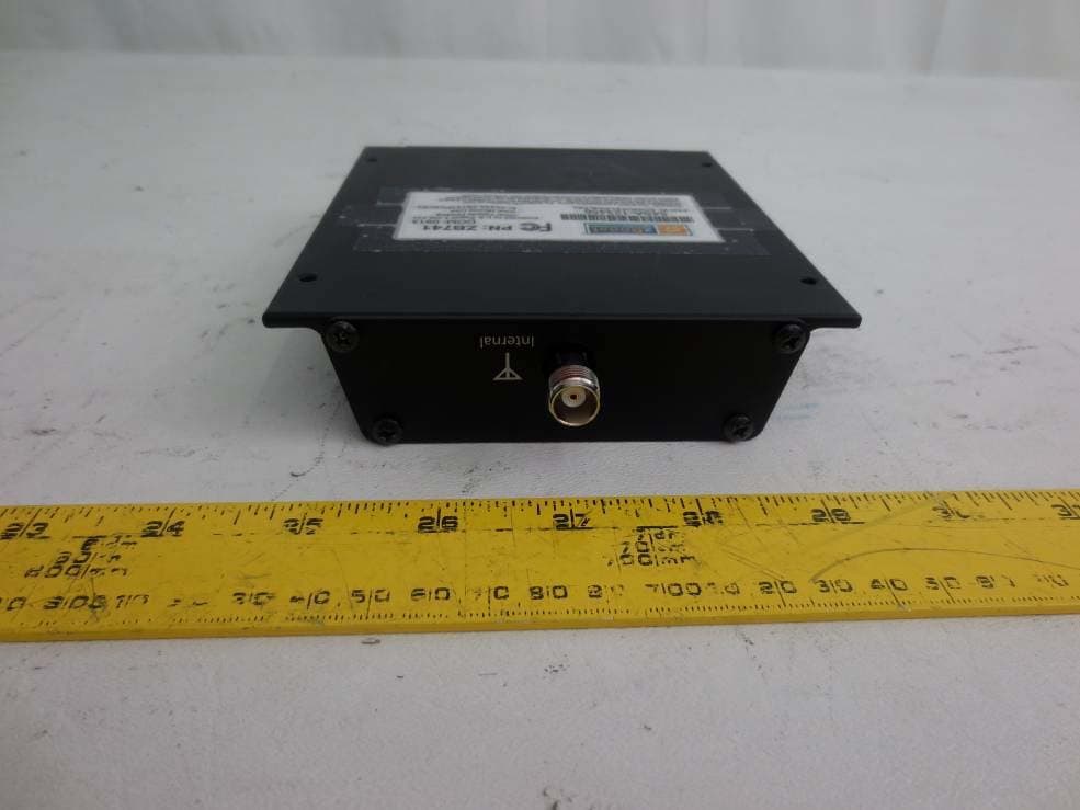
SO4YX741-PCS-CEL
Mar 18, 2014Industrial Booster
Equipment Class
B2I - Part 20 Industrial Booster (CMRS)
SO4YX550-AWS-ALTE
Feb 14, 20134G Cellular Signal Amplifier
Equipment Class
AMP - Amplifier
SO4YX550-AWS-VLTE
Jul 16, 20124G Cellular Signal Amplifier
Equipment Class
TNB - Licensed Non-Broadcast Station Transmitter
SO4YX545-PCS-CEL2
May 23, 2012Cellular Signal Booster
Equipment Class
PCB - PCS Licensed Transmitter