SO4YX510-CELCELLULAR BI- DIRECTIONAL SIGNAL BOOSTER
zBoost, LLC
Click to zoom
Application Details
- Equipment Class
- TNB - Licensed Non-Broadcast Station Transmitter
- Date of Grant
- Dec 28, 2006
- Application Purpose
- Original Equipment
- Date of Application
- Dec 28, 2006
- Equipment Note
- CELLULAR BI- DIRECTIONAL SIGNAL BOOSTER
- Frequency Range
- 869.00000000 - 894.00000000
- Company
- zBoost, LLC
- Country
- United States
Documents & Files
Document Text
Text extracted from the exhibit documents filed with the FCC. Open a document above to read the original.
Users Manual
5015 B.U. Bowman Drive Buford, GA 30518 USA Voice: 770-831-8048 Fax: 770-831-8598 FCC Part 22 Transmitter Certification Test Report FCC ID: SO4YX510-CEL FCC Rule Part: CFR 47 Part 22 Subpart H ACS Report Number: 06-0291-22H Manufacturer: Wireless Extenders Equipment Type: Cellular Bi-Directional Signal Booster Model: YX510-CEL Manual Wi-Ex zBoost YX500/510 Series Installation Guide i Trademarks Wireless Extenders, Wi-Ex, the Wi-Ex logo, zBoost, the zBoost logo, Extending Cell Zones and Wireless Where You Want It are registered trademarks of Wireless Extenders, Inc. iDEN is a registered trademark of Motorola. Nextel is a registered trademark of Nextel Communications Corp. Canada IC :5544A-YX500CEL :5544A-YX500PCS :5544A-YX510 This Class B digital apparatus meets all requirements of the Canadian Interference Causing Equipment Regulations. Operation is subject to the following two conditions: (1) this device may not cause harmful interference, and (2) this device must accept any interference received, including interference that may cause undesired operation. Cet appareillage numérique de la classe [B] répond à toutes les exigences de l'interférence canadienne causant des règlements d'équipement. L'opération est sujette aux deux conditions suivantes: (1) ce dispositif peut ne pas causer l'interférence nocive, et (2) ce dispositif doit accepter n'importe quelle interférence reçue, y compris l'interférence qui peut causer l'opération peu désirée. Industry Canada Regulations This manual is copyrighted. All rights reserved. This manual, whole or in part, may not be copied, photocopied, reproduced, translated, or reduced to any electronic medium or machine- readable form for distribution. This manual, whole or in part, may not be modified without prior consent, in writing, from Wireless Extenders. Copyright © 2006 by Wireless Extenders, Inc. FCC Information FCC ID: SO4YX500-CEL : SO4YX500-PCS :SO4YX510 This equipment has been tested and found to comply with the limits for a Class B digital device, pursuant to Part 15 of the FCC Rules. These limits are designed to provide reasonable protection against harmful interference in the residential installation. This equipment generates, uses, and can radiate radio frequency energy and, if not installed and used in accordance with the instructions, may cause harmful interference to radio communications. However, there is no guarantee that interference will not occur in a particular installation. If this equipment does cause harmful interference to radio or television reception, which can be determined by turning the equipment off and on, the user is encouraged to try to correct the interference by one or more of the following measures: • Connect the equipment into an outlet on a circuit different from that to which the receiver is connected • Increase the separation between the equipment and receiver. • Reorient or relocate the receiving Connect the equipment into an outlet on a circuit different from that to which the receiver is connected. • Consult the dealer or a professional installer for help. Copyright Notice Wi-Ex zBoost YX500/510 Series Installation Guide ii Read First Before Installing Your zBoost Product Before unpacking this box, verify that your phone operates on the frequency band supported by this product. - The YX500-CEL will enhance your in-building coverage for local provider networks operating at the 800MHz (Cellular) frequency. - The YX500-PCS will enhance your in-building coverage for local provider networks operating at the 1900MHz (PCS) frequency. - The YX510-PCS-CEL will work for both Cellular and PCS frequencies. (NOTE) The YX500 Series is not compatible with iDEN, Nextel, SMR or ESMR frequency services. To verify that your phone will work in conjunction with the model purchased, please follow these four simple steps: 1) Unpack the Base Unit, Base Unit Antenna and power supply only. 2) Connect the Base Unit Antenna and the power supply to Base Unit and plug it into an outlet. The green power light will illuminate. 3) Bring the unit to an area where there is enough signal to place a call (using an extension cord may be necessary). If the Signal light begins flashing green while placing a call, you can proceed with the installation of the system. If it flashes red, move your phone further away from the Base Unit (typical for GSM) and retry. 4) If the Signal light does not flash green, try to place another call with your cell phone directly touching the unit. If the Signal Light still does not flash green, your cell phone may be operating on frequency supported by a different model. Some carriers, such as Cingular and Verizon change frequency depending upon location. Go to www.wirelessadvisor.com or contact Wi-Ex technical support at 1-800-871-1612 for further assistance. Wi-Ex zBoost YX500/510 Series Installation Guide iii Safety and Product Warranty Information Safety Guidelines Please adhere to the following safety guidelines during the installation of your Product 1 ) In accordance with FCC requirements of human exposure to radiofrequency fields, the radiating element (antenna) shall be installed such that a minimum separation distance of 8 inches (20cm) is maintained between the radiating element and the user and/or general population. 2) If a ladder is required for install, make sure that the ladder feet are on a flat surface and the ladder is securely fixed. It is highly recommended that you have someone assist you while you are on a ladder 3) You should always wear proper eye protection when working with power tools. 4) Keep all plastic bags away from children to avoid suffocation hazard. 5) Before drilling make sure you know the location of existing electrical wiring to avoid contact with the wiring which could cause an electrical shock and severe the wiring. Limited Liability In no event shall Wireless Extenders be liable for any direct, indirect, special, punitive, incidental, exemplary or consequential damages, or any da…
Text truncated - open the document above for the full version.
Cover Letter(s)
One Meca Way Norcross, Georgia 30093 Ph: 770-239-5475 x2478 Fax: 770-239-5473 CONFIDENTIALITY REQUEST Federal Communications Commission Date: 12/15/06 Equipment Authorization Branch 7435 Oakland Mills Road Columbia, MD 21046 Gentlemen: Wireless Extenders, Inc. respectfully requests confidentiality of certain materials provided with the submission of the YX510-CEL under FCC ID: S04YX510-CEL in accordance with FCC Regulations 0.459. This confidentiality request applies to the exhibits contained in this filing and list below. (1) Schematic diagrams (06-0291C – Schematics.pdf) (2) Detailed block diagrams (06-0291C – System Block Diagram.pdf) (3) Operational descriptions (06-0291C – Theory of Operation.pdf) (4) Parts lists (06-0291C – Parts List.pdf) (5) Tune up procedures. (06-291C – Tune-up Procedure.pdf) The YX510-CEL has been developed at considerable effort and expense by Wireless Extenders, Inc. These items are considered as Trade Secrets and therefore public access to the proprietary material could possible result in duplication of equipment that could severely damage the company's business advantage. I appreciate your assistance in this matter. Sincerely, Name: Pieter C. Seidel Signature: Title: Engineering Manager Date: 12/15/06
External Photos
5015 B.U. Bowman Drive Buford, GA 30518 USA Voice: 770-831-8048 Fax: 770-831-8598 FCC Part 22 Transmitter Certification Test Report FCC ID: SO4YX510-CEL FCC Rule Part: CFR 47 Part 22 Subpart H ACS Report Number: 06-0291-22H Manufacturer: Wireless Extenders Equipment Type: Cellular Bi-Directional Signal Booster Model: YX510-CEL External Photographs Model: YX510-CEL FCC ID: SO4YX510-CEL 5015 B.U. Bowman Drive Buford, GA 30518 USA Voice: 770-831-8048 Fax: 770-831-8598 Figure 1: External - Top Model: YX510-CEL FCC ID: SO4YX510-CEL 5015 B.U. Bowman Drive Buford, GA 30518 USA Voice: 770-831-8048 Fax: 770-831-8598 Figure 2: External – Bottom Model: YX510-CEL FCC ID: SO4YX510-CEL 5015 B.U. Bowman Drive Buford, GA 30518 USA Voice: 770-831-8048 Fax: 770-831-8598 Figure 3: External - Side Model: YX510-CEL FCC ID: SO4YX510-CEL 5015 B.U. Bowman Drive Buford, GA 30518 USA Voice: 770-831-8048 Fax: 770-831-8598 Figure 4: External - Side
Internal Photos
5015 B.U. Bowman Drive Buford, GA 30518 USA Voice: 770-831-8048 Fax: 770-831-8598 FCC Part 22 Transmitter Certification Test Report FCC ID: SO4YX510-CEL FCC Rule Part: CFR 47 Part 22 Subpart H ACS Report Number: 06-0291-22H Manufacturer: Wireless Extenders Equipment Type: Cellular Bi-Directional Signal Booster Model: YX510-CEL Internal Photographs Model: YX510-CEL FCC ID: SO4YX510-CEL 5015 B.U. Bowman Drive Buford, GA 30518 USA Voice: 770-831-8048 Fax: 770-831-8598 Figure 1: Internal – PCB Front Model: YX510-CEL FCC ID: SO4YX510-CEL 5015 B.U. Bowman Drive Buford, GA 30518 USA Voice: 770-831-8048 Fax: 770-831-8598 Figure 2: Internal – PCB Front – Unshielded Model: YX510-CEL FCC ID: SO4YX510-CEL 5015 B.U. Bowman Drive Buford, GA 30518 USA Voice: 770-831-8048 Fax: 770-831-8598 Figure 3: Internal – PCB Back Model: YX510-CEL FCC ID: SO4YX510-CEL 5015 B.U. Bowman Drive Buford, GA 30518 USA Voice: 770-831-8048 Fax: 770-831-8598 Figure 4: Internal – PCB Back – Unshielded
RF Exposure Info
5015 B.U. Bowman Drive Buford, GA 30518 USA Voice: 770-831-8048 Fax: 770-831-8598 FCC Part 22 Transmitter Certification Test Report FCC ID: SO4YX510-CEL FCC Rule Part: CFR 47 Part 22 Subpart H ACS Report Number: 06-0291-22H Manufacturer: Wireless Extenders Equipment Type: Cellular Bi-Directional Signal Booster Model: YX510-CEL RF Exposure Model: YX510-CEL FCC ID: SO4YX510-CEL 5015 B.U. Bowman Drive Buford, GA 30518 USA Voice: 770-831-8048 Fax: 770-831-8598 General Information: Applicant: Wireless Extenders ACS Project: 06-0291C FCC ID: SO4YX510-CEL Device Category: Uplink – Fixed, Downlink - Mobile Exposure Conditions: Uncontrolled/General Population Technical Information: Note: Multiple antennas are available with this device. Antennas specified below indicate the antennas with the maximum gain for each path. UPLINK: Antenna Type: Yagi Antenna Gain Maximum: 15dBi Max Transmitter Output Power: 25.48dBm Max System EIRP: 40.48dBm / 11.2W Operating Configuration: Fixed DOWNLINK: Antenna Type: Directional Panel Antenna Gain Maximum: 6dBi Max Transmitter Output Power: 3.94dBm Max System EIRP: 9.94dBm / 0.010W Operating Configuration: Mobile NOTE: Multiple antennas are available for both the uplink and downlink applications. Listed above are antennas with the highest gain. MPE Calculation The Power Density (mW/cm 2 ) is calculated as follows: S = 2 4R PG π Where: S = power density (in appropriate units, e.g. mW/cm2) P = power input to the antenna (in appropriate units, e.g., mW) G = power gain of the antenna in the direction of interest relative to an isotropic radiator R = distance to the center of radiation of the antenna (appropriate units, e.g., cm) Calculations were performed at the frequencies with the highest output power as determined during testing. Maximum Permissible Exposure (MPE) General Population/Uncontrolled Exposure 83625.480.56353.181531.623 400.555Uplink 8943.940.602.4863.981200.002Downlink Configuaration Power De nsity (mW/cm^2) Dista nce (cm) Transmit Frequency (MHz) Radio Power (dBm) Power Density Limit (mW /Cm2) Radio Power (mW ) Antenna Gain (dBi) Antenna Gain (mW e q.) Installation Guidelines End-users and installers must be provided with antenna installation instructions and transmitter operating conditions for satisfying RF exposure compliance.
Test Report
5015 B.U. Bowman Drive Buford, GA 30518 USA Voice: 770-831-8048 Fax: 770-831-8598 FCC Part 22 Transmitter Certification Test Report FCC ID: SO4YX510-CEL FCC Rule Part: CFR 47 Part 22 Subpart H ACS Report Number: 06-0291-22H Manufacturer: Wireless Extenders Equipment Type: Cellular Bi-Directional Signal Booster Model: YX510-CEL Test Begin Date: October 4, 2006 Test End Date: December 1, 2006 Report Issue Date: December 20, 2006 FOR THE SCOPE OF ACCREDITATION UNDER LAB Code 200612 Prepared by: Reviewed by: J. Kirby Munroe Manager Wireless Certifications ACS, Inc. R. Sam Wismer Engineering Manager ACS, Inc. This test report shall not be reproduced except in full. This report may be reproduced in part with prior written consent of ACS, Inc. The results contained in this report are representative of the sample(s) submitted for evaluation. This report contains 18 pages 5015 B.U. Bowman Drive Buford, GA 30518 USA Voice: 770-831-8048 Fax: 770-831-8598 Table of Contents 1.0 General 3 1.1 Purpose 3 1.2 Product Description 3 1.2.1 General 3 1.3 Test Methodology and Considerations 3 2.0 Test Facilities 4 2.1 Location 4 2.2 Laboratory Accreditations/Recognitions/Certifications 4 2.3 Radiated Emissions Test Site Description 4 2.3.1 Semi-Anechoic Chamber Test Site 5 2.3.2 Open Area Tests Site (OATS) 6 2.4 Conducted Emissions Test Site Description 7 3.0 Applicable Standards and References 7 4.0 List of Test Equipment 8 5.0 Support Equipment and Accessories 9 6.0 EUT Setup and Block Diagram 9 7.0 Summary of Tests 10 7.1 RF Power Output 10 7.1.1 Measurement Procedure 10 7.1.2 Measurement Results 10 7.2 Occupied Bandwidth (Emission Limits) 11 7.2.1 Measurement Procedure 11 7.2.2 Measurement Results 11 7.3 Spurious Emissions at Antenna Terminals and Inter-modulation Products 12 7.3.1 Measurement Procedure 12 7.3.2 Measurement Results 12 7.4 Band-edge Compliance 14 7.4.1 Measurement Procedure 14 7.4.2 Measurement Results 14 7.5 Field Strength of Spurious Emissions 15 7.5.1 Measurement Procedure 15 7.5.2 Measurement Results 15 7.6 Frequency Response 16 7.5.1 Measurement Procedure 16 7.5.2 Measurement Results 16 7.7 Radiated Emissions (Unintentional Radiators) 17 7.7.1 Measurement Procedure 17 7.7.2 Measurement Results 17 7.8 Power Line Conducted Emissions 18 7.8.1 Measurement Procedure 18 7.8.2 Measurement Results 18 Additional Exhibits Included In Filing Internal Photographs External Photographs Test Setup Photographs Product Labeling RF Exposure – MPE Calculations Installation/Users Guide Theory of Operation Parts List System Block Diagram Tune-up Procedure Schematics Model: YX510-CEL FCC ID: SO4YX510-CEL ACS Report: 06-0291-22H Advanced Compliance Solutions Page 3 1.0 GENERAL 1.1 Purpose The purpose of this report is to demonstrate compliance with Part 2 Subpart J and Part 22 Subpart H of the FCC’s Code of Federal Regulations. 1.2 Product Description 1.2.1 General The YX510 is a Smart Bi-Directional Amplifier (SBDA) system which captures the signal arriving outside a consumer’s home and amplifies it inside the home, as well as capturing the signal from the user’s phone and amplifying it to the outdoor network. Wireless Extenders designed the YX510 to meet BOTH the needs of the wireless carrier and the wireless consumer. The YX510 is available in three model variants, YX510-CEL, YX510-PCS, and a dual band version YX510-PCS-CEL. All models utilize the same PCB, which is fully populated for the YX510-PCS-CEL model to offer dual band capabilities. For the single band model variants the PCB portion which is not utilized is depopulated. This report addresses the YX510-CEL operation only. An additional report is available for the YX510-PCS operation. Manufacturer Information: Wi-Ex One Meca Way Norcross, GA 30093 Detailed photographs of the EUT are filed separately with this filing. 1.3 Test Methodology and Considerations The EUT was configured and tested utilizing the maximum input drive level resulting in maximum gain conditions for all tests. If the maximum input drive level is exceeded, internal attenuators are activated to produce a level RF output and eliminate the device from operating beyond the maximum RF output power that is below the saturated RF output power. For unintentional radiated emissions measurements the EUT was configured with one port loaded with a 50 Ohm non-radiating load and the other port loaded with a representative antenna. Both ports could not be loaded with representative antennas within the test environment due to the isolation required between antennas and the fact the device would receive and transmit any received signals via the antennas. Both the uplink and downlink ports were evaluated with antennas attached and the worst case provided in this report. Model: YX510-CEL FCC ID: SO4YX510-CEL ACS Report: 06-0291-22H Advanced Compliance Solutions Page 4 2.0 TEST FACILITIES 2.1 Location The radiated and conducted emissions test sites are located at the following address: Advanced Compliance Solutions 5015 B.U. Bowman Drive Buford, GA 30518 Phone: (770) 831-8048 Fax: (770) 831-8598 2.2 Laboratory Accreditations/Recognitions/Certifications The Semi-Anechoic Chamber Test Site, Open Area Test Site (OATS) and Conducted Emissions Site have been fully described, submitted to, and accepted by the FCC, Industry Canada and the Japanese Voluntary Control Council for Interference by information technology equipment. In addition, ACS is compliant to ISO 17025 as certified by the National Institute of Standards and Technology under their National Voluntary Laboratory Accreditation Program. The following certification numbers have been issued in recognition of these accreditations and certifications: FCC Registration Number: 89450 Industry Canada Lab Code: IC 4175 VCCI Member Number: 1831 VCCI OATS Registration Number R-1526 VCCI Conducted Emissions Site Registration Number: C-1608 NVLAP Lab Code: 200612-0 Model: YX510-CEL FCC ID: SO4YX510-CEL ACS Report: 06-0291-22H Advanced Compliance Solutio…
Text truncated - open the document above for the full version.
Test Report
5015 B.U. Bowman Drive Buford, GA 30518 USA Voice: 770-831-8048 Fax: 770-831-8598 FCC Part 22 Transmitter Certification Test Report FCC ID: SO4YX510-CEL FCC Rule Part: CFR 47 Part 22 Subpart H ACS Report Number: 06-0291-22H-A Manufacturer: Wireless Extenders Equipment Type: Cellular Bi-Directional Signal Booster Model: YX510-CEL Test Begin Date: October 4, 2006 Test End Date: December 1, 2006 Report Issue Date: December 20, 2006 FOR THE SCOPE OF ACCREDITATION UNDER LAB Code 200612 Prepared by: Reviewed by: J. Kirby Munroe Manager Wireless Certifications ACS, Inc. R. Sam Wismer Engineering Manager ACS, Inc. This test report shall not be reproduced except in full. This report may be reproduced in part with prior written consent of ACS, Inc. The results contained in this report are representative of the sample(s) submitted for evaluation. This report contains 34 pages ACS Report: 05-0291-22H-A Advanced Compliance Solutions Page 2 Table of Contents 1.0 Occupied Bandwidth 1.1 Uplink 3 1.2 Downlink 6 2.0 Spurious Emissions at Antenna Terminals and Inter-modulation Products 2.1 CDMA Uplink 9 2.2 TDMA Uplink 12 2.3 CW Uplink 15 2.4 GSM Uplink 17 2.5 CDMA Downlink 19 2.6 TDMA Downlink 22 2.7 CW Downlink 25 2.8 GSM Downlink 27 3.0 Band-edge 3.1 CDMA Uplink 29 3.2 TDMA Uplink 30 3.3 GSM Uplink 31 3.4 CDMA Downlink 32 3.5 TDMA Downlink 33 3.6 GSM Downlink 34 Model: YX510-CEL FCC ID: SO4YX510-CEL ACS Report: 05-0291-22H-A Advanced Compliance Solutions Page 3 1.0 Occupied Bandwidth (Input vs. Output) 1.1 Uplink A SGL Offset 6 dB LVL * * RBW 30 kHz VBW 100 kHz SWT 2.5 msRef 0 dBmAtt 30 dB * Center 824.7 MHzSpan 2 MHz200 kHz/ 1 PK VIEW 2 PK MAXH * -100 -90 -80 -70 -60 -50 -40 -30 -20 -10 0 Date: 27.NOV.2006 11:56:31 Figure 1: Occupied Bandwidth - Uplink CDMA Low Channel A SGL Offset 6 dB LVL Ref 0 dBmAtt 30 dB * 200 kHz/Center 836.52 MHzSpan 2 MHz * * RBW 30 kHz VBW 100 kHz SWT 2.5 ms 2 PK VIEW * 1 PK VIEW -100 -90 -80 -70 -60 -50 -40 -30 -20 -10 0 Date: 27.NOV.2006 11:58:29 Figure 2: Occupied Bandwidth - Uplink CDMA Mid Channel A SGL Offset 6 dB LVL Ref 0 dBmAtt 30 dB * 200 kHz/Center 848.31 MHzSpan 2 MHz * * RBW 30 kHz VBW 100 kHz SWT 2.5 ms 1 PK VIEW 2 PK MAXH * -100 -90 -80 -70 -60 -50 -40 -30 -20 -10 0 Date: 27.NOV.2006 12:00:07 Figure 3: Occupied Bandwidth - Uplink CDMA High Channel Model: YX510-CEL FCC ID: SO4YX510-CEL ACS Report: 05-0291-22H-A Advanced Compliance Solutions Page 4 A SGL Offset 6 dB LVL * * RBW 300 Hz VBW 1 kHz SWT 1.15 sRef 0 dBmAtt 30 dB * Center 824.04 MHzSpan 100 kHz10 kHz/ 1 PK VIEW 2 PK MAXH * -100 -90 -80 -70 -60 -50 -40 -30 -20 -10 0 1 Marker 1 [T1 ] -78.35 dBm 823.990000000 MHz Date: 27.NOV.2006 11:48:34 Figure 4: Occupied Bandwidth - Uplink TDMA Low Channel A SGL Offset 6 dB LVL Ref 0 dBmAtt 30 dB * 10 kHz/Center 836.52 MHzSpan 100 kHz * * RBW 300 Hz VBW 1 kHz SWT 1.15 s 2 PK VIEW 1 PK MAXH * -100 -90 -80 -70 -60 -50 -40 -30 -20 -10 0 1 Marker 1 [T1 ] -77.05 dBm 836.470000000 MHz Date: 27.NOV.2006 11:51:26 Figure 5: Occupied Bandwidth - Uplink TDMA Mid Channel A SGL Offset 6 dB LVL Ref 0 dBmAtt 30 dB * 10 kHz/Center 848.97 MHzSpan 100 kHz * * RBW 300 Hz VBW 1 kHz SWT 1.15 s 1 PK VIEW 2 PK MAXH * -100 -90 -80 -70 -60 -50 -40 -30 -20 -10 0 1 Marker 1 [T1 ] -76.43 dBm 848.920000000 MHz Date: 27.NOV.2006 11:53:35 Figure 6: Occupied Bandwidth - Uplink TDMA High Channel Model: YX510-CEL FCC ID: SO4YX510-CEL ACS Report: 05-0291-22H-A Advanced Compliance Solutions Page 5 A SGL * * RBW 3 kHz VBW 10 kHz SWT 200 msAtt 30 dB * Ref 6 dBm Offset 6 dB Center 824.2 MHzSpan 1 MHz100 kHz/ LVL 1 PK VIEW 2 PK MAXH * -90 -80 -70 -60 -50 -40 -30 -20 -10 0 Date: 27.NOV.2006 11:40:29 Figure 7: Occupied Bandwidth - Uplink GSM Low Channel A SGL Att 30 dB * Ref 6 dBm Offset 6 dB LVL 100 kHz/Center 836.6 MHzSpan 1 MHz * * RBW 3 kHz VBW 10 kHz SWT 200 ms 2 PK VIEW 1 PK MAXH * -90 -80 -70 -60 -50 -40 -30 -20 -10 0 Date: 27.NOV.2006 11:42:47 Figure 8: Occupied Bandwidth - Uplink GSM Mid Channel A SGL Att 30 dB * Ref 6 dBm Offset 6 dB LVL 100 kHz/Center 848.8 MHzSpan 1 MHz * * RBW 3 kHz VBW 10 kHz SWT 200 ms 1 PK VIEW 2 PK MAXH * -90 -80 -70 -60 -50 -40 -30 -20 -10 0 Date: 27.NOV.2006 11:44:51 Figure 9: Occupied Bandwidth - Uplink GSM High Channel Model: YX510-CEL FCC ID: SO4YX510-CEL ACS Report: 05-0291-22H-A Advanced Compliance Solutions Page 6 1.2 Downlink A SGL * * RBW 30 kHz VBW 100 kHz SWT 2.5 msRef 0 dBmAtt 30 dB * Center 869.7 MHzSpan 2 MHz200 kHz/ 1 PK VIEW 2 PK MAXH * -100 -90 -80 -70 -60 -50 -40 -30 -20 -10 0 Date: 27.NOV.2006 11:12:47 Figure 10: Occupied Bandwidth - Downlink CDMA Low Channel A SGL Ref 0 dBmAtt 30 dB * 200 kHz/Center 881.52 MHzSpan 2 MHz * * RBW 30 kHz VBW 100 kHz SWT 2.5 ms 2 PK VIEW 1 PK MAXH * -100 -90 -80 -70 -60 -50 -40 -30 -20 -10 0 Date: 27.NOV.2006 11:14:43 Figure 11: Occupied Bandwidth - Downlink CDMA Mid Channel A SGL Ref 0 dBmAtt 30 dB * 200 kHz/Center 893.31 MHzSpan 2 MHz * * RBW 30 kHz VBW 100 kHz SWT 2.5 ms 1 PK VIEW 2 PK MAXH * -100 -90 -80 -70 -60 -50 -40 -30 -20 -10 0 Date: 27.NOV.2006 11:16:36 Figure 12: Occupied Bandwidth - Downlink CDMA High Channel Model: YX510-CEL FCC ID: SO4YX510-CEL ACS Report: 05-0291-22H-A Advanced Compliance Solutions Page 7 A SGL * * RBW 300 Hz VBW 1 kHz SWT 1.15 sRef 0 dBmAtt 30 dB * Center 869.04 MHzSpan 100 kHz10 kHz/ 1 PK VIEW 2 PK MAXH * -100 -90 -80 -70 -60 -50 -40 -30 -20 -10 0 1 Marker 1 [T1 ] -78.46 dBm 869.090000000 MHz Date: 27.NOV.2006 11:20:11 Figure 13: Occupied Bandwidth - Downlink TDMA Low Channel A SGL Ref 0 dBmAtt 30 dB * 10 kHz/Center 881.52 MHzSpan 100 kHz * * RBW 300 Hz VBW 1 kHz SWT 1.15 s 1 PK VIEW 2 PK MAXH * -100 -90 -80 -70 -60 -50 -40 -30 -20 -10 0 1 Marker 1 [T1 ] -76.23 dBm 881.470000000 MHz Date: 27.NOV.2006 11:22:21 Figure 14: Occupied Bandwidth - Downlink TDMA Mid Channel A SGL Ref 0 dBmAtt 30 dB * 10 kHz/Center 893.97 MHzSpan 100 kHz * * RBW 300 Hz VBW 1 kHz SWT 1.15 s 1 PK VIEW 2 PK MAXH * -100 -90 -80 -70 -60 -50 -40 -30 -20 -10 0 1 Marker 1 [T1 ] -61.30 dBm 893.920000000 MHz Date: 27.NOV.2006 11…
Text truncated - open the document above for the full version.
Test Setup Photos
5015 B.U. Bowman Drive Buford, GA 30518 USA Voice: 770-831-8048 Fax: 770-831-8598 FCC Part 22 Transmitter Certification Test Report FCC ID: SO4YX510-CEL FCC Rule Part: CFR 47 Part 22 Subpart H ACS Report Number: 06-0291-22H Manufacturer: Wireless Extenders Equipment Type: Cellular Bi-Directional Signal Booster Model: YX510-CEL Test Setup Photographs Model: YX510-CEL FCC ID: SO4YX510-CEL 5015 B.U. Bowman Drive Buford, GA 30518 USA Voice: 770-831-8048 Fax: 770-831-8598 Figure 1: Test Setup – Intentional Spurious Emissions Model: YX510-CEL FCC ID: SO4YX510-CEL 5015 B.U. Bowman Drive Buford, GA 30518 USA Voice: 770-831-8048 Fax: 770-831-8598 Figure 2: Test Setup – Intentional Spurious Emissions Model: YX510-CEL FCC ID: SO4YX510-CEL 5015 B.U. Bowman Drive Buford, GA 30518 USA Voice: 770-831-8048 Fax: 770-831-8598 Figure 3: Test Setup – Intentional Spurious Emissions - Substitution Model: YX510-CEL FCC ID: SO4YX510-CEL 5015 B.U. Bowman Drive Buford, GA 30518 USA Voice: 770-831-8048 Fax: 770-831-8598 Figure 4: Test Setup – Unintentional Radiated Emissions Figure 5: Test Setup – Unintentional Radiated Emissions Model: YX510-CEL FCC ID: SO4YX510-CEL 5015 B.U. Bowman Drive Buford, GA 30518 USA Voice: 770-831-8048 Fax: 770-831-8598 Figure 6: Test Setup – AC Power line Conducted Emissions Figure 6: Test Setup – AC Power line Conducted Emissions
Contact Information
Applicant
Scott Terry(VP of Engineering)
Test Firm
Advanced Compliance Solutions, Inc.Sam Wismer
Technical Specifications
| # | Rule Parts | Frequency Range | Power Output | Emission | Tolerance |
|---|---|---|---|---|---|
| 8 | 22H | 869 MHz - 894 MHz | 2.40 mW | F1D | Amp |
Other Applications from zBoost, LLC

SO4ZB570-PCS-CEL
Mar 19, 2014Part 20 Wideband Consumer Booster
Equipment Class
B2W - Part 20 Wideband Consumer Booster (CMRS)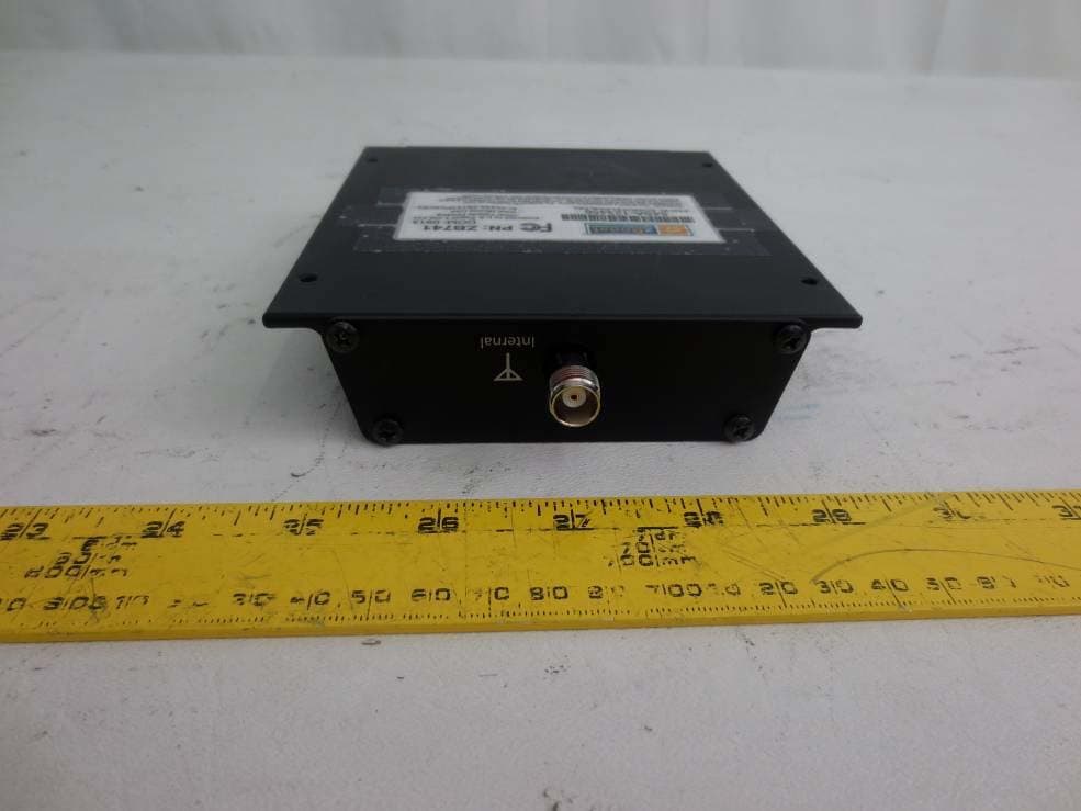
SO4YX741-PCS-CEL
Mar 18, 2014Industrial Booster
Equipment Class
B2I - Part 20 Industrial Booster (CMRS)
SO4YX550-AWS-ALTE
Feb 14, 20134G Cellular Signal Amplifier
Equipment Class
AMP - Amplifier
SO4YX550-AWS-VLTE
Jul 16, 20124G Cellular Signal Amplifier
Equipment Class
TNB - Licensed Non-Broadcast Station Transmitter
SO4YX545-PCS-CEL2
May 23, 2012Cellular Signal Booster
Equipment Class
PCB - PCS Licensed Transmitter