SQCAB5C1Bluetooth Module
Wireless Cables Inc.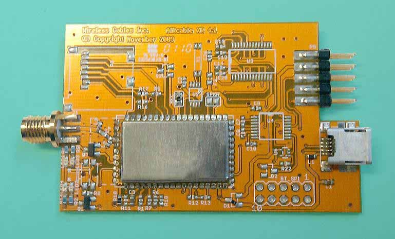
Click to zoom
Application Details
- Equipment Class
- DSS - Part 15 Spread Spectrum Transmitter
- Date of Grant
- Mar 19, 2010
- Application Purpose
- Original Equipment
- Date of Application
- Mar 19, 2010
- Equipment Note
- Bluetooth Module
- Frequency Range
- 2402.00000000 - 2480.00000000
- Company
- Wireless Cables Inc.
- Country
- United States
Documents & Files
Document Text
Text extracted from the exhibit documents filed with the FCC. Open a document above to read the original.
Users Manual
AIRcable Host XR - Professional Antenna Installation Guide Rev. C January 2010 Summary This manual covers the installation of optional directional 18dBi patch antennas and optional 9dBi omni-directional rubber duck antennas for use with the AIRcable Host XR, wireless Bluetooth - Computer interface (dongle), containing part number AB5C1. The use of directional, higher gain antennas is classified by the FCC as a professional installation for a fixed point-to-point application. The use of higher gain omni-directional antennas with more than 6dBi is must also be professionally installed. To be in compliance with FCC requirements, the AIRcable Host XR must be installed only with the approved type of directional patch antenna with a gain of less or equal of 18dBi or with the approved type of omni-directional antenna with a gain of less or equal of 9dBi. FCC Information This device complies with Part 15 of FCC Rules and Regulations. Operation is subject to the following two conditions: (1) This device may not cause harmful interference and (2) this device must accept any interference received, including interference that may cause undesired operation. This equipment has been tested and found to comply with the limits for a Class B digital device, pursuant to Part 15 of the FCC Rules. These limits are designed to provide reasonable protection against harmful interference in a residential installation. This equipment generates, uses, and can radiate radio frequency energy and, if not installed and used in accordance with these instructions, may cause harmful interference to radio communications. However, there is no guarantee that interference will not occur in any particular installation. If this equipment does cause harmful interference to radio or television reception, which can be determined by turning the equipment off and on, the user is encouraged to correct the interference by one of more of the following measures: 1. Reorient the antenna; 2. Increase the separation between the affected equipment and the unit; 3. Connect the affected equipment to a power outlet on a different circuit from that which the receiver is connected to; 4. Consult the dealer and/or experienced radio/TV technician for help. FCC ID: SQCAB5C1 IMPORTANT NOTE:Intentional or unintentional changes or modifications must not be made unless under the express consent of the party responsible for compliance. Any such modifications could void the user’s authority to operate the equipment and will void the manufacturer’s warranty. To comply with FCC RF exposure requirements, the following antenna installation and device operating configurations must be satisfied. The antenna for this unit must be fixed and mounted on outdoor permanent structures with a separation distance of at least 20cm from all persons. Furthermore, it must not be co- located or operating in conjunction with any other antenna or transmitter. Warranty Information All products from Wireless Cables Inc. are warranted from one year from date of purchase. Please see www.aircable.net for complete description of warranty coverage and limitations. WARNING Connections The AIRcable Host XR comes equipped with a professional reverse-polarity SMA (RP- SMA) connector for attachment to an external antenna. To attach the directional patch antenna a pig-tail cable from N-Type to RP-SMA must be used according to the specification. Length of the pig-tail must not be shorter than 3 feet with a loss of 0.5 dB. Installer must cover cable-connector with heat shrink tubing to provide weatherproofing of the RF cable connectors. The following pig-tail cable has been approved by the FCC: Antenna Type Due to FCC restrictions the professional installer must ensure that only directional patch type antennas of gains with less or equal of 18dBi are used. For these antenna this device does not require manual power limit settings since the maximum output power of the AIRcable Host XR is under 20dBm. Application The FCC restricts the use of directional antennas to fixed point-to-point operation. The antenna must be installed on a pole using the supplied mounting hardware per drawing below. The omni-directional antenna must be used directly connected to the AIRcable Host XR without a cable pig-tail. Screw on the antenna to the antenna port of the device and align the antenna vertically. Only antennas of that type with gain of less or equal 18dBi (directional) and less or equal 9dBi (omni-directional) are certified by the FCC and allowed to use with the AIRcable Host XR. Antenna ModelAntenna Gain ANT2400D18W 18dBi directional ANT2400Q9P 9dBi omni-directional Antenna Alignment The directional antenna must be aligned for optimal performance. The antenna shall be aimed at the peer and precisely aligned for a maximum signal strength. The AIRcable Host XR provides Relative Signal Strength Indicator through the standard Bluetooth interface. Please note that the Bluetooth radio adjusts the output power to the situation. A relative zero is a good and solid connection. The omni-directional rubber-duck antenna must be aligned vertically to give an optimum horizontal radiation pattern.
Users Manual
Wireless Cables Inc. 2880 Zanker Rd, Suite 203 San Jose, CA 95134 Phone: (408) 850-1884 Fax: (408) 228-0687 Email: [email protected] Bluetooth Module AIRcable SMD, AB5C1 USER GUIDE V1.1 Federal Communication Commission Interference Statement This equipment has been tested and found to comply with the limits for a Class B digital device, pursuant to Part 15 of the FCC Rules. These limits are designed to provide reasonable protection against harmful interference in a residential installation. This equipment generates, uses and can radiate radio frequency energy and, if not installed and used in accordance with the instructions, may cause harmful interference to radio communications. However, there is no guarantee that interference will not occur in a particular installation. If this equipment does cause harmful interference to radio or television reception, which can be determined by turning the equipment off and on, the user is encouraged to try to correct the interference by one of the following measures: ● Reorient or relocate the receiving antenna. ● Increase the separation between the equipment and receiver. ● Connect the equipment into an outlet on a circuit different from that to which the receiver is connected. ● Consult the dealer or an experienced radio/TV technician for help. FCC Caution: Any changes or modifications not expressly approved by the party responsible for compliance could void the user's authority to operate this equipment. This device complies with Part 15 of the FCC Rules. Operation is subject to the following two conditions: (1) This device may not cause harmful interference, and (2) this device must accept any interference received, including interference that may cause undesired operation. IMPORTANT NOTE: FCC Radiation Exposure Statement: This equipment complies with FCC radiation exposure limits set forth for an uncontrolled environment. This transmitter must not be co-located or operating in conjunction with any other antenna or transmitter. Wireless Cables Inc. 2880 Zanker Rd, Suite 203 San Jose, CA 95134 Phone: (408) 850-1884 Fax: (408) 228-0687 Email: [email protected] This mobile device is intended for general use. THE TRANSMITTING ANTENNA MUST BE LOCATED MORE THAN 20cm AWAY FROM THE BODY OF USER AND NEAR BY PERSON. 1) The transmitter module may not be co-located with any other transmitter or antenna. As long as condition above are met, further transmitter test will not be required. However, the OEM integrator is still responsible for testing their end-product for any additional compliance requirements required with this module installed (for example, digital device emissions, PC peripheral requirements, etc.). IMPORTANT NOTE: In the event that these conditions can not be met (for example certain laptop configurations or co-location with another transmitter), then the FCC authorization is no longer considered valid and the FCC ID can not be used on the final product. In these circumstances, the OEM integrator will be responsible for re-evaluating the end product (including the transmitter) and obtaining a separate FCC authorization. End Product Labeling The final end product must be labeled in a visible area with the following: “Contains FCC ID: SQCAB5C1”. Manual Information That Must be Included The users manual must include the following information in a prominent location: Example Sticker: This Transmitter must not be co-located or operating in conjunction with any other antenna or transmitter. This equipment complies with FCC RF radiation exposure limits set forth for an uncontrolled nvironment. This equipment should be installed and operated with a minimum distance of 20 centimeters between the radiator and your body. Any changes or modifications (including the antennas) made to this device that are not expressly approved by the manufacturer may void the user’s authority to operate the equipment. IMPORTANT NOTE: Wireless Cables Inc. 2880 Zanker Rd, Suite 203 San Jose, CA 95134 Phone: (408) 850-1884 Fax: (408) 228-0687 Email: [email protected] Description Wireless Cables Inc. provides various Bluetooth products. They are suitable for customers to exploit them to implement Bluetooth functionality into PCs. The features of Bluetooth USB interface list as below: Features Model Name AB5C1 Standard Bluetooth v2.1 Frequency Band 2.4~2.4835GHz unlicensed ISM band Spread Spectrum FHSS (Frequency Hopping Spread Spectrum) RF Output Power Class 1 (18.91 dBm) DC power 5V or Lithium battery I/O Interface USB Compliant USB V2.1 Overair Baud rate 720kBit/s, Audio intput and output, differential 16 PIO, 2 AIO, asynchronous and synchronous serial Dimension 25 x 14.5 mm Photos Wireless Cables Inc. 2880 Zanker Rd, Suite 203 San Jose, CA 95134 Phone: (408) 850-1884 Fax: (408) 228-0687 Email: [email protected] Wireless Cables Inc. 2880 Zanker Rd, Suite 203, San Jose, CA 95134 T 408.850.1884 ~ F 408.228.0687 [email protected] ~ www.aircable.net Software Specification Hardware Specification BASIC Interpreter Line numbers: 1-2047 Line length: 32 characters Loop nesting: 6 Subroutines: 8 levels Expressions: -32768 to 32767, 16-bit Variables: 25, ‘A’ - ‘Y’, variable ‘Z’ used for debugging String variable: $0 volatile 80 bytes long String variables: $1-$2047, 32 byte length Character size: 8 bit Expression parser recursive, maximum of 5 levels File system: BASIC and config file independent PIN code limit: 15 characters Programmable from other AIRmote devices Programm load from standard file system Event Handling PIN code request Incoming SPP connection Outgoing SPP connection success Sensor readings (connection quality, temperature, analog input) Incoming vNote through OBEX Inquiry results SPP control indicator (DTR signal) PIO change event Timer messages Interrupt Routines 2 levels: high priority interrupt: stops BASIC program execution low priority: schedules execution Bluetooth Bluetooth 2.1 certified, with 802.11 tolerance EDR supported where available Profiles…
Text truncated - open the document above for the full version.
Attestation Statements
Wireless Cables Inc. 2880 Zanker Rd, Suite 203 San Jose, CA 95134 Phone: (408) 850-1884 Fax: (408) 228-0687 Email: [email protected] Bluetooth Declaration Per FCC 15.247 Requirements 1 Output power and channel separation of a Bluetooth device in the different operating modes: The different operating modes (data-mode, acquisition-mode) of a Bluetooth device don’t influence the output power and the channel spacing. There is only one transmitter which is driven by identical input parameters concerning these two parameters. Only a different hopping sequence will be used. For this reason the check of these RF parameters in one op-mode is sufficient. 2 Frequency range of a Bluetooth device: Hereby we declare that the maximum frequency of this device is: 2402 – 2480 MHz. This is according the Bluetooth Core Specification V 1.0B (+ critical errata) for devices which will be operated in the USA. This was checked during the Bluetooth Qualification tests (Test Case: TRM/CA/04-E). Other frequency ranges ( e.g. for Spain, France, Japan) which are allowed according the Core Specification are not supported by this device. 3 Co-ordination of the hopping sequence in data mode to avoid simultaneous occupancy by multiple transmitters: Bluetooth units which want to communicate with other units must be organized in a structure called piconet. This piconet consist of max. 8 Bluetooth units. One unit is the master the other seven are the slaves. The master co-ordinates frequency occupation in this piconet for all units. As the master hop sequence is derived from it’s BD address which is unique for every Bluetooth device, additional masters intending to establish new piconets will always use different hop sequences. 4 Example of a hopping sequence in data mode: Example of a 79 hopping sequence in data mode: 40, 21, 44, 23, 42, 53, 46, 55, 48, 33, 52, 35, 50, 65, 54, 67, 56, 37, 60, 39, 58, 69, 62, 71, 64, 25, 68, 27, 66, 57, 70, 59, 72, 29, 76, 31, 74, 61, 78, 63, 01, 41, 05, 43, 03, 73, 07, 75, 09, 45, 13, 47, 11, 77, 15, 00, 64, 49, 66, 53, 68, 02, 70, 06, 01, 51, 03, 55, 05, 04 5 Equally average use of frequencies in data mode and behaviour for short transmissions: Wireless Cables Inc. 2880 Zanker Rd, Suite 203 San Jose, CA 95134 Phone: (408) 850-1884 Fax: (408) 228-0687 Email: [email protected] The generation of the hopping sequence in connection mode depends essentially on two input values: 1. LAP/UAP of the master of the connection 2. Internal master clock The LAP (lower address part) are the 24 LSB’s of the 48 BD_ADDRESS. The BD_ADDRESS is an unambiguous number of every Bluetooth unit. The UAP (upper address part) are the 24 MSB’s of the 48 BD_ADDRESS. The internal clock of a Bluetooth unit is derived from a free running clock which is never adjusted and is never turned off. For synchronization with other units only offset are used. It has no relation to the time of the day. Its resolution is at least half the RX/TX slot length of 312.5 μs. The clock has a cycle of about one day (23h30). In most case it is implemented as 28 bit counter. For the deriving of the hopping sequence the entire LAP (24 bits), 4 LSB’s (4 bits) (Input 1) and the 27 MSB’s of the clock (Input 2) are used. With this input values different mathematical procedures (permutations, additions, XOR- operations) are performed to generate the sequence. This will be done at the beginning of every new transmission. Regarding short transmissions the Bluetooth system has the following behaviors: The first connection between the two devices is established, a hopping sequence was generated. For transmitting the wanted data the complete hopping sequence was not used. The connection ended. The second connection will be established. A new hopping sequence is generated. Due to the fact that the Bluetooth clock has a different value, because the period between the two transmission is longer (and it cannot be shorter) than the minimum resolution of the clock (312.5 μs). The hopping sequence will always differ from the first one. 6 Receiver input bandwidth and behaviors for repeated single or multiple packets: The input bandwidth of the receiver is 1 MHz. In every connection one Bluetooth device is the master and the other one is the slave. The master determines the hopping sequence (see chapter 5). The slave follows this sequence. Both devices shift between RX and TX time slot according to the clock of the master. Additionally the type of connection (e.g. single or multislot packet) is set up at the beginning of the connection. The master adapts its hopping frequency and its TX/RX timing according to the packet type of the connection. Also the slave of the connection will use these settings. Repeating of a packet has no influence on the hopping sequence. The hopping sequence generated by the master of the connection will be followed in any case. That means, a Wireless Cables Inc. 2880 Zanker Rd, Suite 203 San Jose, CA 95134 Phone: (408) 850-1884 Fax: (408) 228-0687 Email: [email protected] repeated packet will not be send on the same frequency, it is send on the next frequency of the hopping sequence. 7 Dwell time in data mode The dwell time of 0.3797s within a 30 second period in data mode is independent from the packet type (packet length). The calculation for a 30 second period is a follows: Dwell time = time slot length * hop rate / number of hopping channels *30s Example for a DH1 packet (with a maximum length of one time slot) Dwell time = 625 μs * 1600 1/s / 79 * 30s = 0.3797s (in a 30s period) For multislot packet the hopping is reduced according to the length of the packet. Example for a DH5 packet (with a maximum length of five time slots) Dwell time = 5 * 625 μs * 1600 * 1/5 *1/s / 79 * 30s = 0.3797s (in a 30s period) This is according the Bluetooth Core Specification V 1.0B (+ critical errata) for all Bluetooth devices. There for all Bluetooth devices comply with the FCC dwell time requirement in data mode. This was checked during t…
Text truncated - open the document above for the full version.
Cover Letter(s)
Wireless Cables Inc. 1414 Soquel Avenue, Suite 212 Santa Cruz, CA 95062 Phone: (408) 850-1884 Fax: (408) 228-0687 Email: [email protected] Date: 02/08/2010 Federal Communications Commission 7435 Oakland Mills Road Columbia MD 21046 c.c. Compliance Certification Services Certification Division 47173 Benicia Street Fremont, CA 94538, USA To whom it may concern: I, the undersigned, hereby authorize Mr Jerry Tsai of Telecom Technology Center. and hereafter referred to as Telecom Technology Center, to act on our behalf in all manners relating to application for equipment authorization, including signing of all documents relating to these matters. Any and all acts carried out by Mr Jerry Tsai of Telecom Technology Center. on our behalf shall have the same effect as acts of our own. I, the undersigned, hereby certify that we are not subject to a denial of federal benefits, that includes FCC benefits, pursuant to Section 5301 of the Anti-Drug Abuse Act of 1988, 21 U.S.C. 853(a). In authorizing Telecom Technology Center as our agent, we still recognize that we are responsible to: a) comply with the relevant provisions of the certification program; b) make all necessary arrangements for the conduct of the evaluation, including provision for examining documentation and access to all areas, records (including internal audit reports) and personnel for the purposes of evaluation (e.g. testing, inspection, assessment, surveillance, reassessment) and resolution of complaints; c) make claims regarding certification only in respect of the scope for which certification has been granted; d) do not use our product certification in such a manner as to bring the Certification Division into disrepute and not make any statement regarding our product Wireless Cables Inc. 1414 Soquel Avenue, Suite 212 Santa Cruz, CA 95062 Phone: (408) 850-1884 Fax: (408) 228-0687 Email: [email protected] certification which the Certification Division may consider misleading or unauthorized; e) upon suspension or cancellation of certification, discontinue use of all advertising matter that contains any reference thereto and return any certification documents as required by the Certification Division; f) use certification only to indicate the products are certified as being in conformity with specified standards; g) endeavor to ensure that no certificate or report nor any part thereof is used in a misleading manner; h) ensure that any reference to our product certification in communication media such as documents, brochures or advertising, complies with the requirements of the Certification Division; i) keep a record of all complaints made known to the us relating to the product’s compliance with requirements of the relevant standard and to make these records available to the Certification Division when requested; j) take appropriate action with respect to such complaints and any deficiencies found in products or services that affect compliance with the requirements for certification; k) document the actions taken. This authorization is valid until further written notice from the applicant. Sincerely Yours, Dr. Juergen Kienhoefer CEO Wireless Cables Inc. 02/08/2010
Cover Letter(s)
Applicant/Grantee Wireless Cables Inc. FCC ID: SQCAB5C1 Section 15.212 Modular Transmitters Request for Modular Approval Request for Limited Modular Approval Requirements EUT Conditions Comply (Y/N) Single Modular Approval Requirements 1 The radio elements of the modular transmitter must have their own shielding. The physical crystal and tuning capacitors may be located external to the shielded radio elements. This module uses a fully integrated radio on a single silicon chip. The radio portion as well as the baseband DSP and the main processor of this module has been shielded. The RF silicon design was completed with RF shielding on the silicon design and plastic package using a steel cap. This complies with part 15 FCC requirements for transmission. Additionally, due to the design, it also is immune to external coupling from other circuits in a system. As a result, the device complies with #1 modular transmitter requirements with RF shielding. Please see external photo in User’s Manual. Y 2 The modular transmitter must have buffered modulation/data inputs (if such inputs are provided) to ensure that the module will comply with Part 15 requirements under conditions of excessive data rates or over-modulation. The EUT has buffered data inputs. Y 3 The modular transmitter must have its own power supply regulation. The silicon chip has an internal 1.8V regulator for radio, baseband DSP, and processor. Y 4 The modular transmitter must comply with the antenna and transmission system requirements of Sections 15.203, 15.204(b) and 15.204(c). The antenna must either be permanently attached or employ a “unique” antenna coupler (at all connections between the module and the antenna, including the cable). The “professional installation” provision of Section 15.203 is not applicable to modules but can apply to limited modular approvals under paragraph (b) of this section. The EUT meets the FCC antenna requirements by using an integrated ceramic antenna. For the 18dBi antenna installation, please refer to “profession installation” for spec and instructions. N 5 The modular transmitter must be tested in a stand-alone configuration, i.e., the module must not be inside another device during testing for compliance with Part 15 requirements. Unless the transmitter module will be battery The EUT was tested in a stand-alone configuration. The module was fixed in Development Kit during the test. Y powered, it must comply with the AC line conducted requirements found in Section 15.207. AC or DC power lines and data input/output lines connected to the module must not contain ferrites, unless they will be marketed with the module (see Section 15.27(a)). The length of these lines shall be the length typical of actual use or, if that length is unknown, at least 10 centimeters to insure that there is no coupling between the case of the module and supporting equipment. Any accessories, peripherals, or support equipment connected to the module during testing shall be unmodified and commercially available (see Section 15.31(i)). 6 The modular transmitter must be equipped with either a permanently affixed label or must be capable of electronically displaying its FCC identification number. (A) If using a permanently affixed label, the modular transmitter must be labeled with its own FCC identification number, and, if the FCC identification number is not visible when the module is installed inside another device, then the outside of the device into which the module is installed must also display a label referring to the enclosed module. This exterior label can use wording such as the following: “Contains Transmitter Module FCC ID: XYZMODEL1” or “Contains FCC ID: XYZMODEL1.” Any similar wording that expresses the same meaning may be used. The Grantee may either provide such a label, an example of which must be included in the application for equipment authorization, or, must provide adequate instructions along with the module which explain this requirement. In the latter case, a copy of these instructions must be included in the application for equipment authorization. (B) If the modular transmitter uses an electronic display of the FCC identification number, the information must be readily accessible and visible on the modular transmitter or on the device in which it is installed. If the module is installed inside another device, then the outside of the device into which the module is installed must display a label referring to the enclosed module. This exterior label can use wording such as the following: “Contains FCC certified transmitter module(s).” Any similar wording that expresses the same meaning may be used. The user manual must include instructions on how to access the electronic display. A copy of these instructions There is label showing “Contains FCC ID: SQCAB5C1” on the end product. The proposed FCC ID label format is included in the filing. When the module is installed inside of an end product, OEM customer will be instructed on how to apply the exterior label. Relevant OEM labeling requirements are present in the product user’s manual. Y must be included in the application for equipment authorization. 7 The modular transmitter must comply with any specific rules or operating requirements that ordinarily apply to a complete transmitter and the manufacturer must provide adequate instructions along with the module to explain any such requirements. A copy of these instructions must be included in the application for equipment authorization. The EUT is compliant with all applicable FCC rules. Detailed instructions for maintaining compliance are given in the User’s Manual. The device is a fully integrated antenna, crystal, RF Transceiver, which has both baseband and RF IC in an encapsulated package. The entire signal chain on receiver (LNA mixer, filters, level shifters, phase detector, equalizer), transmitter (IQ modulator, DACs, filters, mixers and PA) and synthesizer (PLL, VCO, and phase detector) are integ…
Text truncated - open the document above for the full version.
Cover Letter(s)
47173 Benicia Street, Fremont CA 94538 Tel: 510-771-1000, Fax: 510-661-0888 Federal Communication Commissions 7435 Oakland Mills Road Columbia MD 21046 Subject: Request FCC to replace previous submitted user manual Ref: Applicant: Wireless Cables Inc. FCC ID: SQCAB5C1 TCB Assessment no.: AN10T0146 Grant date: 03/20/2010 To Whom It May Concern: CCS-TCB issued the grant on 03/20/2010; during the internal audit process, CCS found that previous version of Modular approval request letter was mistakenly uploaded during the upload process. CCS-TCB is requesting FCC to delete the file of Modular approval request letter uploaded in 03/20/2010 from the database and supersede by the attached file "Modular approval request letter_revised". Thank you. Best Regards Mike Kuo / V.P. Compliance Certification Services March 22, 2010
External Photos
Report No.: W-N-1002002-DN-01-1 FCC ID: SQCAB5C1 Date of Issue: February 26, 2010 1 PHOTOGRAPHS OF EUT Report No.: W-N-1002002-DN-01-1 FCC ID: SQCAB5C1 Date of Issue: February 26, 2010 2 Report No.: W-N-1002002-DN-01-1 FCC ID: SQCAB5C1 Date of Issue: February 26, 2010 3 Report No.: W-N-1002002-DN-01-1 FCC ID: SQCAB5C1 Date of Issue: February 26, 2010 4 Report No.: W-N-1002002-DN-01-1 FCC ID: SQCAB5C1 Date of Issue: February 26, 2010 5 Report No.: W-N-1002002-DN-01-1 FCC ID: SQCAB5C1 Date of Issue: February 26, 2010 6
Internal Photos
Report No.: W-N-1002002-DN-01-1 FCC ID: SQCAB5C1 Date of Issue: February 26, 2010 1 PHOTOGRAPHS OF EUT Report No.: W-N-1002002-DN-01-1 FCC ID: SQCAB5C1 Date of Issue: February 26, 2010 2 Report No.: W-N-1002002-DN-01-1 FCC ID: SQCAB5C1 Date of Issue: February 26, 2010 3
RF Exposure Info
MPE evaluation Calculation Given 3770 & 30 2 E S d xPxG E== Where E = Field strength in Volts/meter P = Power in Watts G = Numeric antenna gain d = Distance in meters S = Power density in milliwatts /square centimeter Combining equations and re-arranging the terms to express the distance as a function of the remaining variables yields: 2 3770 30 d xPxG S= Changing to units of mW and cm, using: P (mW) = P(W) / 1000 and d (cm) =d(m) / 100 Yields 22 0796.0 )100/(3770 )1000/(30 d PxG x dx xGPx S== Equation 1 Where d = Distance in cm P = Power in mW G = Numeric antenna gain S = Power density in mW / cm 2 Maximum Permissible Exposure EUT output power =77.8mW Antenna Gain = 7.943 (Numeric gain) (9dBi) Antenna Gain = 63.096 (Numeric gain) (18dBi) Substituting the MPE safe distance using d = 20 cm into Equation 1: Yields S=0.000199 x P x G Where P = Power in mW G = Numeric antenna gain S = Power density in mW / cm 2 → Power density = 0.123mW/cm 2 (9dBi) → Power density = 0.977mW/cm 2 (18dBi) (For mobile or fixed location transmitters, the maximum power density is 1.0 mW/ cm 2 even if the calculation indicates that the power density would be larger.)
Test Report
Report No.: W-N-1002002-DN-01-1 FCC ID: SQCAB5C1 Date of Issue: March.01, 2010 Note: This report shall not be reproduced except in full, without the written approval of Telecom Technology Center. This document may be altered or revised by Telecom Technology Center personnel only, and shall be noted in the revision section of the document. Page 1 Total Page: 80 Rev. 00 FCC 47 CFR PART 15 SUBPART C TEST REPORT For Bluetooth Module Model: AB5C1 Trade Name: AIRcable SMD Issued to Wireless Cables Inc. 3410 Bowman Ct., Santa Cruz, CA 95065, USA Issued by Telecom Technology Center 4F., No.300, Yang Guang St., Neihu Dist., Taipei City 114, Taiwan (R.O.C.) http://www.ttc.org.tw/ [email protected] Report No.: W-N-1002002-DN-01-1 FCC ID: SQCAB5C1 Date of Issue: March.01, 2010 Page 2 TABLE OF CONTENTS 1. TEST RESULT CERTIFICATION.................................................…
Text truncated - open the document above for the full version.
Contact Information
Applicant
Juergen G. Kienhoefer(CEO)
Test Firm
Telecom Technology CenterHsuan-Yu Lin
Technical Specifications
| # | Rule Parts | Frequency Range | Power Output |
|---|---|---|---|
| 1 | 15C | 2.40 GHz - 2.48 GHz | 79.00 mW |
Other Applications from Wireless Cables Inc.
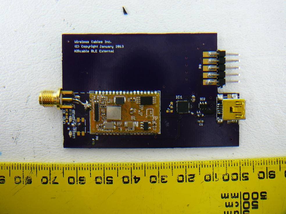
SQCBLE1K
Apr 11, 2013Bluetooth 4.0 Low Energy Single Mode Module
Equipment Class
DTS - Digital Transmission System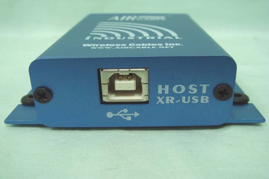
SQCACC1600
Sep 05, 2007Bluetooth USB computer interface
Equipment Class
DSS - Part 15 Spread Spectrum Transmitter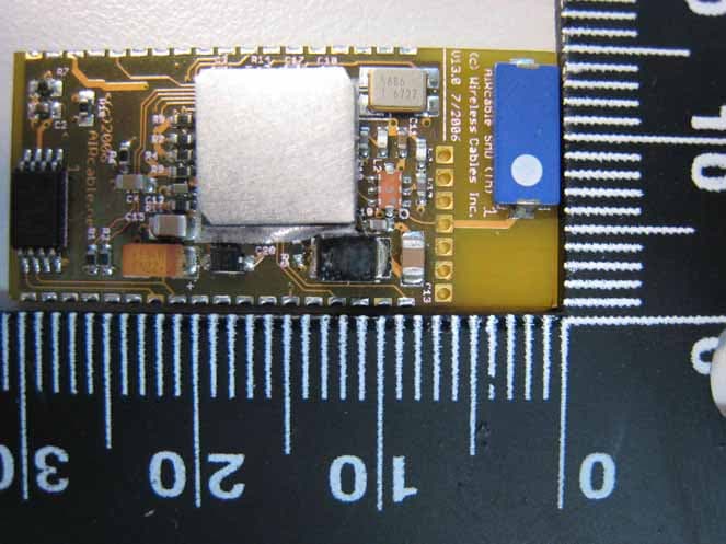
SQCAB3C2
Jun 17, 2007Bluetooth Module
Equipment Class
DSS - Part 15 Spread Spectrum Transmitter
SQCACC1300
Mar 09, 2005Bluetooth Serial Interface
Equipment Class
DSS - Part 15 Spread Spectrum Transmitter