SQCACC1300Bluetooth Serial Interface
Wireless Cables Inc.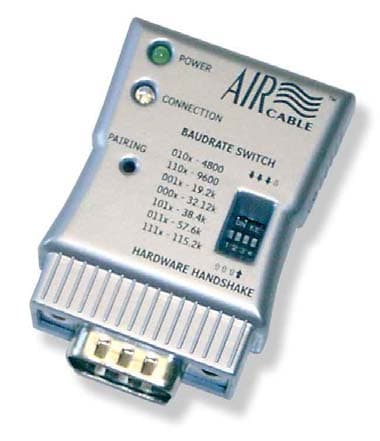
Click to zoom
Application Details
- Equipment Class
- DSS - Part 15 Spread Spectrum Transmitter
- Date of Grant
- Mar 09, 2005
- Application Purpose
- Original Equipment
- Date of Application
- Nov 23, 2004
- Equipment Note
- Bluetooth Serial Interface
- Frequency Range
- 2402.00000000 - 2480.00000000
- Company
- Wireless Cables Inc.
- Country
- United States
Documents & Files
Document Text
Text extracted from the exhibit documents filed with the FCC. Open a document above to read the original.
Users Manual
AIRcable User Manual AIRcable Serial Model 1302 Wireless Bluetooth to Serial Adapter User Guide Rev 0.95 December 7, 2004 Thank you for purchasing an AIRcable. Your satisfaction is very important to us, so please read this guide before installing your AIRcable modules. We’d appreciate your feedback. For more information and instructions or for support please visit our website at http://www.aircable.net The AIRcable product is a Bluetooth to serial adapter for cable replacement functions with user accessible command line for configuration. The AIRcable product is Bluetooth 1.1 certified. AIRcable modules are intelligent and run firmware-based onboard Bluetooth connection software. There is no need to install and configure extra software to establish a wireless connection. Because the AIRcable is designed to replace physical connections, you can run the same software that would support a physical cable. Each module has a button accessible through a hole in the device which is used to pair two modules to become a point-to-point “Wireless Cable™”. During this pairing process, make sure no other Bluetooth device is discoverable within range (approx. 10 meters). Each module has one power LED (green) which shows that the firmware is running correctly and a connection LED (blue) that shows the status of a connection. The connection LED is on solid if a connection to another device is active. Otherwise it is blinking or it is off. The AIRcable Serial is fully Bluetooth 1.1 certified and is compatible with all other Bluetooth 1.1 compatible devices. The AIRcable Serial is compilant with RS-232 serial industrial standard EIA-232-E. There are two different versions available: The DTE has a Sub-D 9 pin female connector and the DCE has a Sub-D 9 pin male adapter. The AIRcable Serial supports all modem control signals, including DTR, DSR, and DCD. Data flow control is implemented using RTS/CTS handshake. Data mode by default is 8 bit, no parity, one stop bit. NOTE: Because the devices implement hardware handshake, the RTS/CTS lines have to be connected or it must be switched off . If your device does not support hardware handshake you must switch off hardware handshake with the 4th switch on the AIRcable switch (down) in order for the AIRcable Serial to work properly. Pin 9 can also be used for powering the AIRcable Serial module. Apply 5-15V DC, plus to pin 9, GND is pin 5 instead of using an external power adapter. Page 1 of 7AIRcable User Manual Baudrate Selection and Switches The AIRcable Serial provides switches accessible from the top to select the baud rate. Switch up is on or '1'. Down means off or '0'. The 4th switch is for hardware handshake. Up means hardware handshake is switched on, down means off. SW1 SW2 SW3 Baud Rate 0 0 0 31.25 kbit/s 0 0 1 19.2 k 0 1 0 4.8 k 0 1 1 56.7 k 1 0 0 4.8 k 1 0 1 38.4 k 1 1 0 9.6 k 1 1 1 115.2 k Page 2 of 7AIRcable User Manual Configuration When you receive an AIRcable Serial, the device must be configured. AIRcable devices support these modes: z Cable Mode z Service Mode z Manual Mode Cable Mode In cable-mode, two AIRcable devices are paired together and create a bond so no other device can interfere. To pair two AIRcables use this simple procedure: 1. Press and hold the pairing button for 5 seconds. The AIRcable module automatically configures itself and starts in slave mode. The power LED (green) will be on again and the connection LED (blue) starts flashing rapidly. 2. Do this on both devices that are going to be paired. 3. On one device press the pairing button again (short click) to change the mode to master. At this time the two devices will find each other, pair and establish a connection. 4. The pairing information has been stored in flash and the two AIRcable modules will connect automatically when they are powered on. No other device can connect to either AIRcable. Advanced Modes The AIRcable Serial can be set into various advanced modes. Use the command line interface to change into these modes. z Service-Slave mode z Service-Master mode z Manual mode Using the Command Line Interface The command line interface is available through the serial interface before the AIRcable device is connected. This means that the connection LED must be either blinking or off. The serial parameters for the command line interface are fixed at: • 115200 baud (AIRcable for Motorola is at 57600 baud) • no parity, one stop bit, 8 bit data, hardware handshake enabled Use a serial null-modem cable to plug the AIRcable Serial with a male type DB9 connector into a PC. Each command starts with a “^A” (control-A or 0x1) character, then follows one of the commands listed below in all caps letters and finishes with a single <CR> (carriage return or 0xd). The command has to be completed within 3 seconds. Otherwise the received characters are deleted and ignored. All commands respond with an "OK". Be aware that some commands in some states require the device to reset. They are marked with (*). This process will take a few seconds during which the AIRcable will not respond to any commands. The power light will go out briefly. Service-Slave Mode In the Service-Slave Mode, the AIRcable allows other Bluetooth devices to connect to it. This mode can be used to allow a Palm with Bluetooth or a Laptop with Bluetooth support to connect. The main advantage of this mode is that it allows several devices to connect to it as oppose to the previously described point-to-point cable modes. Page 3 of 7AIRcable User Manual In order to switch the AIRcable module into “Service-Slave Mode” use the command line interface detailed below. This is just an example. Please adjust the commands to the situation you need, including your security needs. • Reset the AIRcable to the factory default value and delete all pairing information "^A Z <CR> • Change the name of the device ”^A N AIRcable <CR>”: set the name to AIRcable. The name has to be exactly 8 characters long. Use spaces to fill up. • Configure the P…
Text truncated - open the document above for the full version.
Users Manual
1 of 6 AIRcable User Manual AIRcable Serial Model 1302 Wireless Bluetooth to Serial Adapter User Guide Rev 0.97 January 12, 2005 Thank you for purchasing an AIRcable. Your satisfaction is very important to us, so please read this guide before installing your AIRcable modules. We’d appreciate your feedback. For more information and instructions or for support please visit our website at http://www.aircable.net The AIRcable product is a Bluetooth to serial adapter for cable replacement functions with user accessible command line for configuration. The AIRcable product is Bluetooth 1.1 certified. AIRcable modules are intelligent and run firmware-based onboard Bluetooth connection software. There is no need to install and configure extra software to establish a wireless connection. Because the AIRcable is designed to replace physical connections, you can run the same software that would support a physical cable. Each module has a button accessible through a hole in the device which is used to pair two modules to become a point-to-point “Wireless Cable™”. During this pairing process, make sure no other Bluetooth device is discoverable within range (approx. 10 meters). Each module has one power LED (green) which shows that the firmware is running correctly and a connection LED (blue) that shows the status of a connection. The connection LED is on solid if a connection to another device is active. Otherwise it is blinking or it is off. The AIRcable Serial is fully Bluetooth 1.1 certified and is compatible with all other Bluetooth 1.1 compatible devices. The AIRcable Serial is compilant with RS-232 serial industrial standard EIA-232-E. There are two different versions available: The DTE has a Sub-D 9 pin female connector and the DCE has a Sub-D 9 pin male adapter. The AIRcable Serial supports all modem control signals, including DTR, DSR, and DCD. Data flow control is implemented using RTS/CTS handshake. Data mode by default is 8 bit, no parity, one stop bit. NOTE: Because the devices implement hardware handshake, the RTS/CTS lines have to be connected or it must be switched off. If your device does not support hardware handshake you must switch off hardware handshake with the 4th switch on the AIRcable switch (down) in order for the AIRcable Serial to work properly. Pin 9 can also be used for powering the AIRcable Serial module. Apply 5-15V DC, plus to pin 9, GND is pin 5 instead of using an external power adapter. 2 of 6 Baudrate Selection and Switches The AIRcable Serial provides switches accessible from the top to select the baud rate. Switch up is on or '1'. Down means off or '0'. The 4th switch is for hardware handshake. Up means hardware handshake is switched on, down means off. SW1SW2SW3Baud Rate 00031.25 kbit/s 00119.2 k 0104.8 k 01156.7 k 1004.8 k 10138.4 k 1109.6 k 111115.2 k Configuration When you receive an AIRcable Serial, the device must be configured. AIRcable devices support these modes: Cable Mode Service Mode Manual Mode Cable Mode In cable-mode, two AIRcable devices are paired together and create a bond so no other device can interfere. To pair two AIRcables use this simple procedure: Press and hold the pairing button for 5 seconds. The AIRcable module automatically configures itself and starts in slave mode. The power LED (green) will be on again and the connection LED (blue) starts flashing rapidly. 1. Do this on both devices that are going to be paired.2. On one device press the pairing button again (short click) to change the mode to master. At this time the two devices will find each other, pair and establish a connection. 3. The pairing information has been stored in flash and the two AIRcable modules will connect automatically when they are powered on. No other device can connect to either AIRcable. 4. Advanced Modes The AIRcable Serial can be set into various advanced modes. Use the command line interface to change into these modes. 3 of 6 Service-Slave mode Service-Master mode Manual mode Using the Command Line Interface The command line interface is available through the serial interface before the AIRcable device is connected. This means that the connection LED must be either blinking or off. The serial parameters for the command line interface are fixed at: • 115200 baud (AIRcable for Motorola is at 57600 baud) • no parity, one stop bit, 8 bit data, hardware handshake enabled Use a serial null-modem cable to plug the AIRcable Serial with a male type DB9 connector into a PC. Each command starts with a “^A” (control-A or 0x1) character, then follows one of the commands listed below in all caps letters and finishes with a single <CR> (carriage return or 0xd). The command has to be completed within 3 seconds. Otherwise the received characters are deleted and ignored. All commands respond with an "OK". Be aware that some commands in some states require the device to reset. They are marked with (*). This process will take a few seconds during which the AIRcable will not respond to any commands. The power light will go out briefly. Service-Slave Mode In the Service-Slave Mode, the AIRcable allows other Bluetooth devices to connect to it. This mode can be used to allow a Palm with Bluetooth or a Laptop with Bluetooth support to connect. The main advantage of this mode is that it allows several devices to connect to it as oppose to the previously described point-to-point cable modes. In order to switch the AIRcable module into “Service-Slave Mode” use the command line interface detailed below. This is just an example. Please adjust the commands to the situation you need, including your security needs. • Reset the AIRcable to the factory default value and delete all pairing information "^A Z <CR> • Change the name of the device ”^A N AIRcable <CR>”: set the name to AIRcable. The name has to be exactly 8 characters long. Use spaces to fill up. • Configure the PIN number. Either a fixed 2-5 digit number or an automatically generated 5 digit ID that will be added to the name t…
Text truncated - open the document above for the full version.
Cover Letter(s)
TM Wireless Cables, Inc. 1414 Soquel Avenue, Suite 212 Santa Cruz, CA 95062 Phone: (408) 850-1884 FAX (408) 228-0687 Email: [email protected] Block Diagram ACC1300 November 24, 2004 Federal Communications Commission Authorization and Evaluation Division FCC ID SQCACC1300 Confidentiality Request Pursuant to Sections 0.457 and 0.459 of the Commission’s Rules, the Applicant hereby requests confidential treatment of information accompanying this Application as outlined below: 1. Schematics 2. Operational description 3. Block diagram The above materials contain trade secrets and proprietary information not customarily released to the public. The public disclosure of these matters might be harmful to the Applicant and provide unjustified benefits to its competitors. The Applicant understands that pursuant to Rule 0.457, disclosure of this Application and all accompanying documentation will not be made before the date of the Grant for this Application. Sincerely Juergen Kienhoefer/CEO Wireless Cables Inc.
Cover Letter(s)
TM Wireless Cables, Inc. 1414 Soquel Avenue, Suite 212 Santa Cruz, CA 95062 Phone: (408) 850-1884 FAX (408) 228-0687 Email: [email protected] Confidentiality Request ACC1300 November 24, 2004 Federal Communications Commission Authorization and Evaluation Division FCC ID SQCACC1300 Confidentiality Request Pursuant to Sections 0.457 and 0.459 of the Commission’s Rules, the Applicant hereby requests confidential treatment of information accompanying this Application as outlined below: 1. Schematics 2. Operational description 3. Block diagram The above materials contain trade secrets and proprietary information not customarily released to the public. The public disclosure of these matters might be harmful to the Applicant and provide unjustified benefits to its competitors. The Applicant understands that pursuant to Rule 0.457, disclosure of this Application and all accompanying documentation will not be made before the date of the Grant for this Application. Sincerely Juergen Kienhoefer/CEO Wireless Cables Inc.
External Photos
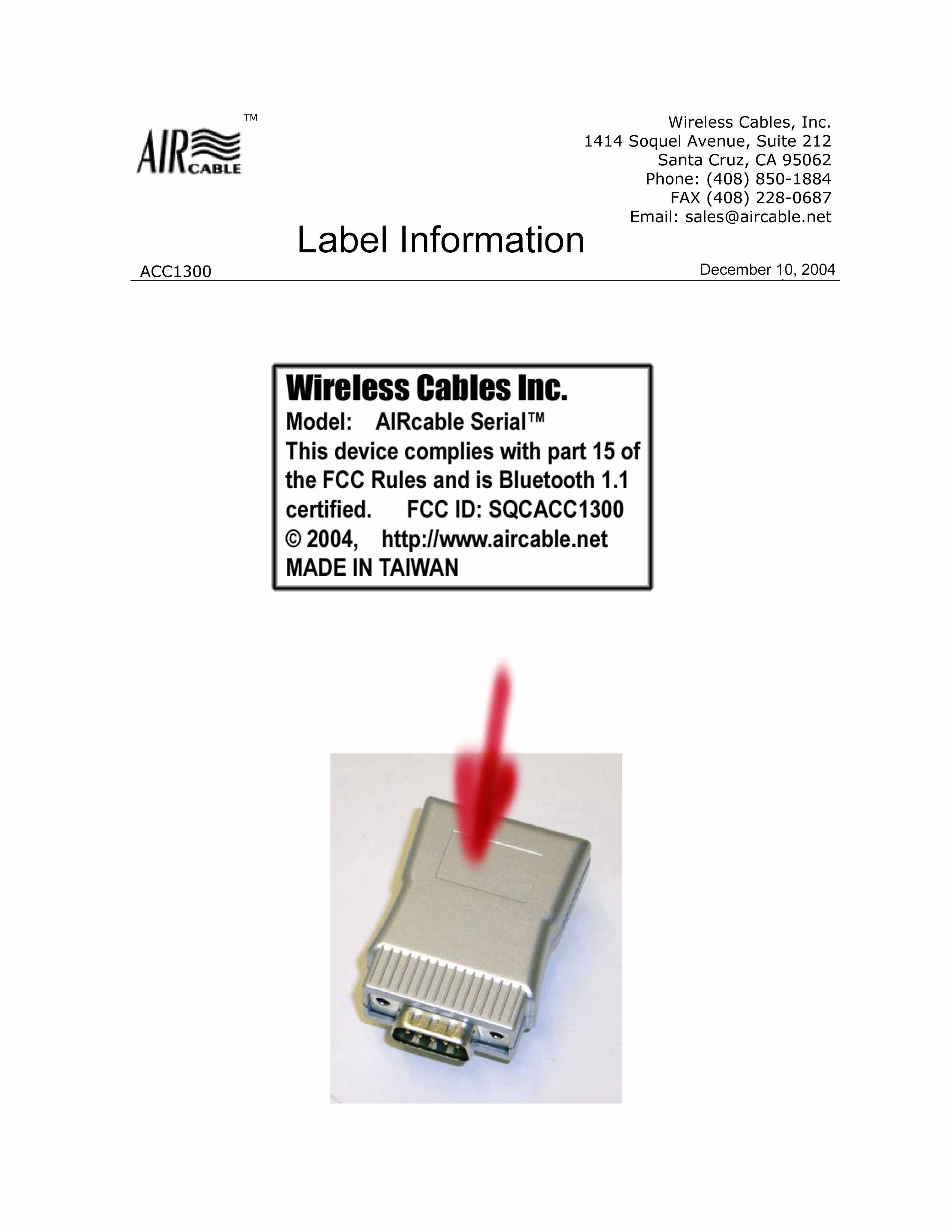
TM Wireless Cables, Inc. 1414 Soquel Avenue, Suite 212 Santa Cruz, CA 95062 Phone: (408) 850-1884 FAX (408) 228-0687 Email: [email protected] External Pictures ACC1300 November 24, 2004
Internal Photos
Compliance Certification Services Inc. Report No: 40715403 Date of Issue: August 11, 2004 Page 2 INTERNAL PHOTOGRPHS OF EUT Compliance Certification Services Inc. Report No: 40715403 Date of Issue: August 11, 2004 Page 3
Internal Photos
TM Wireless Cables, Inc. 1414 Soquel Avenue, Suite 212 Santa Cruz, CA 95062 Phone: (408) 850-1884 FAX (408) 228-0687 Email: [email protected] Internal Pictures ACC1300 November 24, 2004
Parts List/Tune Up Info
1 AN2051 Multilayer Chip Antenna for 2.4GHz Wireless Communication (Advance Information) 2 AN2051 MultilayerChip Antenna ◆Features yMiniaturized size 5.1(L)X2.0(W)X1.2(H) yLight weight and low profile yOmni-directional in azimuth ◆Applications y2.4GHz wireless communications yModules yBluetooth y802.11b yOther 2.4GHz Wireless Application Specifications 2.45GHz 0.5dBi -40 ~ +85 °C -40 ~ +85 °C 2.0 (Max) 50 Ohm 3W (Max) 110MHz Omni-directional Linear Center frequency Peak gain Operation temperature Storage temperature VSWR Input Impedance Power handling Bandwidth Azimuth beamwidth Polarization 3 Pin configuration Solder termination2 Feed termination1 Pin assignmentPin No Dimensions 1.22±0.1H 0.5±0.02C 5.1±0.1B 2.0±0.1A Dimensions(mm)symbol
Parts List/Tune Up Info
Device Features 3.3V power operation Fully qualified by BQB Full speed Bluetooth operation with full piconet support 8M flash memory for application firmware Applications PC Notebooks Cordless Headsets Bluetooth hand free Personal Digital Assistants(PDA) RS-232 Cable replacement USB Dongle Bluetooth HID device(Keyboard, mouse and Joystick) Other Bluetooth specification pforile BLUETOOTH MODULE Model BT-20 BT-20 Module RF IN RF OUT SPI PCM PIO UART/USB Key features Radio No external trimming is required in production. UP to +4dBm RF transmit power Supports Class 2 and Class 3 Radios Baseband/software and physical Interfaces 8M bit slash memory for complete system solution Transcoders for A-law, u=law and linear voice from host and A-law, u-law and CVSD voice over air UART interface with programmable baud rate up to 1.5M Full speed USB interface support BT-20 Bluetooth Module Diagram Device Pinout Diagram Device Pinout Diagram Ground connection Positive power supply 1.8 V output when 3.3V VDD connected UART data input UART request to send UART data output UART clear to send Serial Peripheral Interface data input Serial Peripheral Interface clock Chip select for Synchronous Serial Interface active low Serial Peripheral Interface data output Module reset if high>5ms to cause a reset Programmable I/O line Programmable I/O line No connection No connection Ground connection Description Voltage output for testing1.8V15 GNDGND17 VDD3.3V16 CMOS inputUART_RX14 CMOS outputUART_RTS13 CMOS outputUART_TX12 CMOS inputUART_CTS11 COMS input with weak internal pull-down SPI_MOSI10 COMS input with weak internal pull-down SPI_CLK9 COMS input with weak internal pull-down SPI_CSB8 COMS input with weak internal pull-down SPI_MISO7 COMS input with weak internal pull-down RESET6 Bi-directionAIO(1)5 Bi-directionAIO(0)4 NCNC3 NCNC2 GNDGND1 Pad typePin namePin No. Ground connections for RF circuitry RF single Input and output Ground connections for RF circuitry Programmable I/O line Programmable I/O line Programmable I/O line Programmable I/O line Programmable I/O line Programmable I/O line Programmable I/O line Programmable I/O line USB data minus USB data plus PCM Synchronous data clock PCM Synchronous data input PCM synchronous data SYNC PCM Synchronous data output Description GroundGND32 GroundGND34 RFRF33 Bi-directionPIO(0)31 Bi-directionPIO(1)30 Bi-directionPIO(2)29 Bi-directionPIO(3)28 Bi-directionPIO(4)27 Bi-directionPIO(5)26 Bi-directionPIO(6)25 Bi-directionPIO(7)24 Bi-directionUSB_DN23 Bi-directionUSB_DP22 Bi-directionPCM_CLK21 COMS inputPCM_IN20 Bi-directionPCM_SYNC19 CMOS outputPCM_OUT18 Pad typePin namePin No. Electrical Characteristics +105°C-40°COperating Temperature +120°C-40°CStorage Temperature MaxMinRating Absolute Maximum Ratings 3.6V3.0 VSupply Voltage: MaxMinOperating Condition Recommended Operating Conditions dBm-82-83-2.441 dBm-82-83-2.480 dBm ≤-70 -80-83-2.402 Sensitivity at 0.1% BER dBm Unit ≤-20 Bluetooth Specification Max -5 Typ -Maximum received signal at 0.1% BER Mi n Frequency (GHz) Receiver Radio Characteristics, VDD=3.3V Temperature=+20 °C mA60Peak RF current during TX burst(0dBm) mA0.6Parked Slave, 1.28s beacon interval, 38.4kbps UART uA20Deep Sleep mode mA70Peak RF current during TX burst(+4dBm) mA55Peak RF current during RX burst(-80dBm) mA0.5ACL connection, Sniff mode 1.28s interval, 38.4kbps UART mA4ACL connection, Sniff mode 40ms interval, 38.4kbps UART mA61ACL data transfer 720kbps USB(Master) mA61ACL data transfer 720kbps USB(Slave) mA15ACL data transfer 115.2kbps UART(Master) mA28SCO Connection HV3(Master) mA28SCO connection HV3(Slave) UnitAvgMode Current Consumption VDD=3.3V Schematic Package Dimensions Top View Modulation Testing Bluetooth module testing block BT-20 Module (EUT) Bt-20 Module Test fixture RF Connector Modem Bank Bluetooth test set Control EUT into Bluetooth test mode Remark: RF Connector in test fixture and cable lose about 2.5dBm Bluetooth Modulation Characteristics(by R&S CMU- 200) BQB (Bluetooth Qualification Body) Certificate
Test Report
Compliance Certification Services Inc. Report No.: 41207202-RP1 FCC ID: SQCACC1300 Date of Issue: January 5, 2005 Note: This report shall not be reproduced except in full, without the written approval of Compliance Certification Services Inc. This document may be altered or revised by Compliance Certification Services Inc. personnel only, and shall be noted in the revision section of the document. Page 1 Total Page: 51 Rev. 00 FCC 47 CFR PART 15 Subpart B & Subpart C TEST REPORT For AIRcable Serial Model: ACC1302 Trade Name: Wireless cable Inc. Issued to Wireless Cables Inc. Santa Cruz, California, United States 95065 Issued by Compliance Certification Services Inc. No. 81-1, Lane 210, Bade Rd. 2, Luchu Hsiang, Taoyuan Hsien, (338) Taiwan, R.O.C. TEL: 886-3-324-0332 FAX: 886-3-324-5235 Compliance Certification Services Inc. Report No.: 41207202-RP1 FCC ID: SQCACC1300 Date of Issue: January 5, 2005 Page 2 Rev. 00 TABLE OF CONTENTS 1. TEST RESULT CERTIFICATION ................................................................................................................3 2. EUT DESCRIPTION........................................................................................................................................4 3. TEST METHODOLOGY ................................................................................................................................5 3.1 EUT CONFIGURATION.....................................................................................................................................5 3.2 EUT EXERCISE................................................................................................................................................5 3.3 GENERAL TEST PROCEDURES.........................................................................................................................5 3.4 MODIFICATION..............................................................................................................................................5 3.5 FCC PART 15.205 RESTRICTED BANDS OF OPERATIONS ....................................................................6 3.6 DESCRIPTION OF TEST MODES........................................................................................................................6 4. INSTRUMENT CALIBRATION ....................................................................................................................7 5. FACILITIES AND ACCREDITATIONS ......................................................................................................8 5.1 FACILITIES ...................................................................................................................................................8 5.2 EQUIPMENT ...................................................................................................................................................8 5.3 LABORATORY ACCREDITATIONS AND LISTING...............................................................................................8 5.4 TABLE OF ACCREDITATIONS AND LISTINGS....................................................................................................9 6. SETUP OF EQUIPMENT UNDER TEST ...................................................................................................10 6.1 SETUP CONFIGURATION OF EUT...................................................................................................................10 6.2 SUPPORT EQUIPMENT ..........................................................................................................................10 7. FCC PART 15.247 REQUIREMENTS.........................................................................................................11 7.1 PEAK POWER................................................................................................................................................11 7.2 BAND EDGES MEASUREMENT............................................................................................................12 7.3 PEAK POWER SPECTRAL DENSITY.................................................................................................................17 7.4 FREQUENCY SEPARATION ..................................................................................................................20 7.5 NUMBER OF HOPPING FREQUENCY..................................................................................................22 7.6 TIME OF OCCUPANCY (DWELL TIME) ..............................................................................................24 7.7 RADIO FREQUENCY EXPOSURE.....................................................................................................................31 7.8 SPURIOUS EMISSIONS ............................................................................................................................34 7.9 POWERLINE CONDUCTED EMISSIONS...........................................................................................................46 APPENDIX 1 PHOTOGRAPHS OF TEST SETUP ...........................................................................................50 Compliance Certification Services Inc. Report No.: 41207202-RP1 FCC ID: SQCACC1300 Date of Issue: January 5, 2005 Page 4 Rev. 00 2. EUT DESCRIPTION Product AIRcable Serial Trade Name Wireless Cables Inc. Model Number ACC1302 Model Discrepancy N/A Power Supply Powered from host device Frequency Range 2402 ~ 2480 MHz Transmit Power 5.48 dBm Modulation Technique FHSS, GFSK Transmit Data Rate 1Mbps Number of Channels 79 Channels Antenna Specification Chip Antenna / Gain: 0.5 dBi Note: This submittal(s) (test report) is intended for FCC ID: SQCACC1300 filing to comply with Section 15.107 & 15.109 (FCC Part 15, Subpart B) and Section 15.207, 15.209, 15.247 (FCC Part 15, Subpart C Rules.) Compliance Certification Services Inc. Report No.: 41207202-RP1 FCC ID: SQCACC1300 Date of Issue: January 5, 2005 Page 5 Rev. 00 3. TEST…
Text truncated - open the document above for the full version.
Test Report
Compliance Certification Services Inc. Report No.: 41207202-RP1 FCC ID: SQCACC1300 Date of Issue: January 5, 2005 Note: This report shall not be reproduced except in full, without the written approval of Compliance Certification Services Inc. This document may be altered or revised by Compliance Certification Services Inc. personnel only, and shall be noted in the revision section of the document. Page 1 Total Page: 51 Rev. 00 FCC 47 CFR PART 15 Subpart B & Subpart C TEST REPORT For AIRcable Serial Model: ACC1302 Trade Name: Wireless cable Inc. Issued to Wireless Cables Inc. Santa Cruz, California, United States 95065 Issued by Compliance Certification Services Inc. No. 81-1, Lane 210, Bade Rd. 2, Luchu Hsiang, Taoyuan Hsien, (338) Taiwan, R.O.C. TEL: 886-3-324-0332 FAX: 886-3-324-5235 Compliance Certification Services Inc. Report No.: 41207202-RP1 FCC ID: SQCACC1300 Date of Issue: January 5, 2005 Page 2 Rev. 00 TABLE OF CONTENTS 1. TEST RESULT CERTIFICATION ................................................................................................................3 2. EUT DESCRIPTION........................................................................................................................................4 3. TEST METHODOLOGY ................................................................................................................................5 3.1 EUT CONFIGURATION.....................................................................................................................................5 3.2 EUT EXERCISE................................................................................................................................................5 3.3 GENERAL TEST PROCEDURES.........................................................................................................................5 3.4 MODIFICATION..............................................................................................................................................5 3.5 FCC PART 15.205 RESTRICTED BANDS OF OPERATIONS ....................................................................6 3.6 DESCRIPTION OF TEST MODES........................................................................................................................6 4. INSTRUMENT CALIBRATION ....................................................................................................................7 5. FACILITIES AND ACCREDITATIONS ......................................................................................................8 5.1 FACILITIES ...................................................................................................................................................8 5.2 EQUIPMENT ...................................................................................................................................................8 5.3 LABORATORY ACCREDITATIONS AND LISTING...............................................................................................8 5.4 TABLE OF ACCREDITATIONS AND LISTINGS....................................................................................................9 6. SETUP OF EQUIPMENT UNDER TEST ...................................................................................................10 6.1 SETUP CONFIGURATION OF EUT...................................................................................................................10 6.2 SUPPORT EQUIPMENT ..........................................................................................................................10 7. FCC PART 15.247 REQUIREMENTS.........................................................................................................11 7.1 PEAK POWER................................................................................................................................................11 7.2 BAND EDGES MEASUREMENT............................................................................................................12 7.3 PEAK POWER SPECTRAL DENSITY.................................................................................................................17 7.4 FREQUENCY SEPARATION ..................................................................................................................20 7.5 NUMBER OF HOPPING FREQUENCY..................................................................................................22 7.6 TIME OF OCCUPANCY (DWELL TIME) ..................................................................…
Text truncated - open the document above for the full version.
Contact Information
Applicant
Juergen G. Kienhoefer(CEO)
Test Firm
Compliance Certification Services Inc.Tony Houng
Technical Specifications
| # | Rule Parts | Frequency Range | Power Output |
|---|---|---|---|
| 1 | 15C | 2.40 GHz - 2.48 GHz | 1.10 mW |
Other Applications from Wireless Cables Inc.
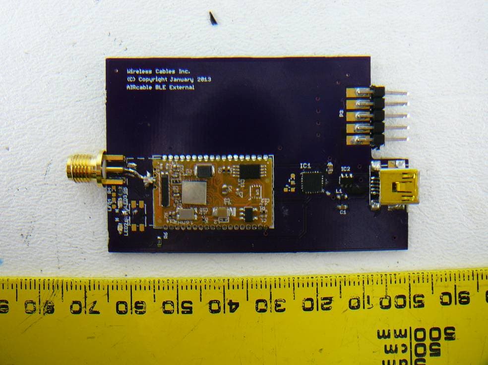
SQCBLE1K
Apr 11, 2013Bluetooth 4.0 Low Energy Single Mode Module
Equipment Class
DTS - Digital Transmission System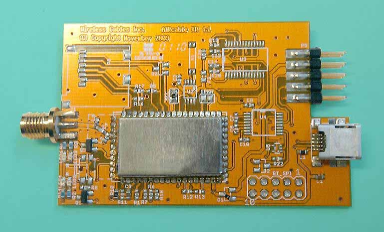
SQCAB5C1
Mar 19, 2010Bluetooth Module
Equipment Class
DSS - Part 15 Spread Spectrum Transmitter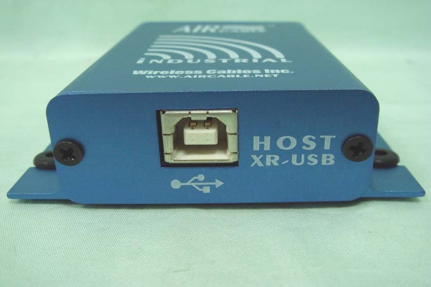
SQCACC1600
Sep 05, 2007Bluetooth USB computer interface
Equipment Class
DSS - Part 15 Spread Spectrum Transmitter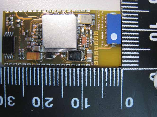
SQCAB3C2
Jun 17, 2007Bluetooth Module
Equipment Class
DSS - Part 15 Spread Spectrum Transmitter