SQG-SERANX040UWB and BLE Module
Laird Connectivity LLC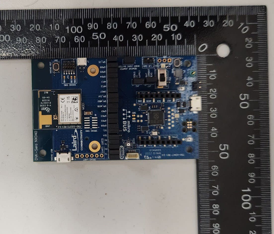
Click to zoom
Application Details
- Equipment Class
- DTS - Digital Transmission System
- Date of Grant
- Dec 19, 2023
- Application Purpose
- Original Equipment
- Date of Application
- Dec 07, 2023
- Equipment Note
- UWB and BLE Module
- Frequency Range
- 2402.00000000 - 2480.00000000
- Company
- Laird Connectivity LLC
- Country
- United States
Documents & Files
Document Text
Text extracted from the exhibit documents filed with the FCC. Open a document above to read the original.
Users Manual
https://www.lairdconnect.com/ 1 © Copyright 2023 Laird Connectivity All Rights Reserved Americas: +1-800-492-2320 Europe: +44-1628-858-940 Hong Kong: +852 2762 4823 NX040 Regulatory Information v1.1 1 CURRENT REGULATORY CERTIFICATIONS The NX040 (P/N 453-00174, 453-00175) holds current certifications in the following countries: Country/Region Regulatory ID USA (FCC) SQG-SERANX040 EU N/A (No ID number required) Canada (ISED) 3147A-SERANX040 UK (UKCA) N/A (No ID number required) Japan (MIC) pending Korea (KC) pending Australia pending New Zealand pending 2 CERTIFIED ANTENNAS The antennas listed below were tested for use with the NX040. The OEM can choose a different manufacturer’s antenna but must make sure it is of same type and that the gain is less than or equal to the antenna that is approved for use.* *Note: Japan (MIC) lists applicable antennas on its certificates. If your antenna is not on the approved list, regardless of whether it is comparative, it must be added to the certificate before it can be used in Japan. Model Type Connector Frequencies / Peak Gain (dBi) Laird Connectivity NanoBlue EBL2400A1-10MH4L PCB Dipole IPEX MHF4 2400 – 2500 MHz / 2 dBi Laird Connectivity FlexPIFA 001-0022 PIFA IPEX MHF4 2400 – 2480 MHz / 2 dBi Mag Layers EDA-8709-2G4C1-B27 0600-00057 Dipole IPEX MHF4 2400 – 2480 MHz / 2 dBi Laird Connectivity mFlexPIFA EFA2400A3S-10MH4L PIFA IPEX MHF4 2400 – 2480 MHz / 2 dBi Laird Connectivity EFG2400A3S-10MH4L PIFA IPEX MHF4L 2400 – 2500 MHz / 3.1 dBi Laird Connectivity Onboard PCB printed BLE antenna 1 Printed PCB N/A 2400 – 2480 MHz / 0.73 dBi Laird Connectivity NanoUWB EUB5850A3S-10MHL4 PCB Monopole IPEX MHF4L 5850 – 8250 MHz / 3.5 dBi Laird Connectivity Onboard PCB printed UWB antenna 1 Printed PCB N/A 6250 – 8250 MHz / 3.5 dBi Laird Connectivity NFC 0600-00061 NFC spiral N/A - Note 1: NX040 PCB printed antennas are only certified for NX040 part number 453-00175. NX040 Regulatory Information https://www.lairdconnect.com/ 2 © Copyright 2023 Laird Connectivity All Rights Reserved Americas: +1-800-492-2320 Europe: +44-1628-858-940 Hong Kong: +852 2762 4823 3 DOCUMENTATION REQUIREMENTS To ensure regulatory compliance, when integrating the NX040 into a host device, it is necessary to meet the documentation requirements set forth by the applicable regulatory agencies. The following sections (FCC, ISED Canada, European Union, and others) outline the information that may be included in the user’s guide and external labels for the host devices into which the NX040 is integrated. 4 FCC REGULATORY Applicaable FCC Rule Parts 15.247 and 15.519 Model Part # US/FCC Sera NX040 453-00174 SQG-SERANX040 Sera NX040 453-00175 SQG-SERANX040 The 453-00174 and the 453-00175 hold full modular approvals. The OEM must follow the regulatory guidelines and warnings listed below and the installation guidance in section 12 to inherit the modular approval. Part # Form Factor BLE Tx Outputs UWB TX Outputs Antenna 453-00174 Surface Mount 8 dBm -41.3dBm/MHz IPEX MHF4L 453-00175 Surface Mount 8 dBm -41.3dBm/MHz PCB Trace 4.1 Antenna Information The NX040 family has been designed to operate with the antennas listed below with a maximum gain of 3.1 dBi in the 2400 – 2500 MHz frequency band and a maximum gain of 3.5 dBi in the 6250 – 8250 MHz frequency band. The required antenna impedance is 50 ohms. Model Type Connector Peak Gain (dBi) Laird Connectivity NanoBlue EBL2400A1-10MH4L 2 PCB Dipole IPEX MHF4 2400 – 2500 MHz 2 dBi Laird Connectivity FlexPIFA 001-0022 2 PIFA IPEX MHF4 2400 – 2480 MHz 2 dBi Mag Layers EDA-8709-2G4C1-B27 0600-00057 2 Dipole IPEX MHF4 2400 – 2480 MHz 2 dBi Laird Connectivity mFlexPIFA EFA2400A3S-10MH4L 2 PIFA IPEX MHF4 2400 – 2480 MHz 2 dBi Laird Connectivity EFG2400A3S-10MH4L 2 PIFA IPEX MHF4L 2400 – 2500 MHz 3.1 dBi Laird Connectivity Onboard PCB printed BLE antenna 1 Printed PCB N/A 2400 – 2480 MHz 0.73 dBi Laird Connectivity NanoUWB EUB5850A3S-10MHL4 2 PCB Monopole IPEX MHF4L 5850 – 8250 MHz 3.5 dBi Laird Connectivity Onboard PCB printed UWB antenna 1 Printed PCB N/A 6250 – 8250 MHz 3.5 dBi Laird Connectivity NFC 0600-00061 2 NFC spiral N/A - Note 1: NX040 PCB printed antennas are only certified for NX040 part number 453-00175. Refer to Section 12 for implementation requirements that must be followed when using this antenna. Note 2: The OEM is free to choose another vendor’s antenna of like type and equal or lesser gain as an antenna appearing in the table and still maintain compliance. Reference FCC Part 15.204(c)(4) for further information on this topic. To reduce potential radio interference to other users, the antenna type and gain should be chosen so that the equivalent isotropic radiated power (EIRP) is not more than that permitted for successful communication. NX040 Regulatory Information https://www.lairdconnect.com/ 3 © Copyright 2023 Laird Connectivity All Rights Reserved Americas: +1-800-492-2320 Europe: +44-1628-858-940 Hong Kong: +852 2762 4823 If you desire to increase antenna gain and either change antenna type or use same antenna type certified, a Class II permissive change application is required to be filed by us, or the host manufacturer can take responsibility through the change in FCC ID (new application) procedure followed by a Class II permissive change application. 4.2 FCC Documentation Requirements This modular transmitter is only FCC authorized for the specific rule parts listed on our grant. The host product manufacturer is responsible for compliance to any other FCC rules that apply to the host not covered by the modular transmitter grant of certification. Federal Communication Commission Interference Statement This equipment has been tested and found to comply with the limits for a Class B digital device, pursuant to Part 15 of the FCC Rules. These limits are designed to provide reasonable protection against harmful interference in a residential installation. This equipment generates, uses, and can radiate radio frequency energy and, if not in…
Text truncated - open the document above for the full version.
Attestation Statements
Certification Application Attestation Statements Date: March 21,2023 To Whom It May Concern: Subject: FCC ID: SQG-SERANX040 Statement for 47 CFR section 2.911(d)(5)(i) Laird Connectivity LLC certifies that as of the date of the application the equipment for which authorization is sought is not “covered” equipment prohibited from receiving an equipment authorization pursuant to section 2.903 of the FCC rules. If the equipment for which the applicant seeks authorization is produced by any of the entities identified on the current Covered List, including affiliates or subsidiaries of the named companies, the applicant must include an explanation on why the equipment is not “covered” equipment. Additional Explanation: <N/A> Statement for 47 CFR section 2.911(d)(5)(ii) Laird Connectivity LLC (“the applicant”) certifies that, as of the date of the filing of this application, the applicant ☐ - is / ☒- is not identified on the Covered List as an entity producing “covered” equipment. Thank you, By: __________________________ Brian Petted (Signature) (Print name) Title: Technology Leader Company: Laird Connectivity LLC Telephone: 262-421-4974
Attestation Statements
U.S. Agent Designation for Service of Process (Applicant is Both Grantee and U.S. Agent) ATTENTION : FCC Certification – Section 2.911(d)(7) Information This letter is to confirm that the Applicant will also serve as the U.S. Agent for Service of Process as required by 47 CFR 2.911(d)(7). The Applicant acknowledges that they must maintain an agent for no less than one year after terminating all marketing and importation OR the conclusion of any Commission-related proceeding involving the equipment. The Applicant further acknowledges their responsibility to inform the FCC whenever the Designated U.S. Agent information changes. Applicant Company name: Laird Connectivity LLC FRN #: 0022590616 Grantee Code: SQG Contact Name: Brian Petted, Technology Leader Street Address: W66 N220 Commerce Court City/Province/Zip: Cedarburg, Wisconsin, 53012 Telephone No: (262)-421-4974 Email:[email protected] Applicant Signature 1 : Date: March 21, 2023 Signed by (Printed Name/Title): Brian Petted, Technology Leader 1 - Letters should be placed on appropriate letterhead.
Attestation Statements
October 20, 2023 The following information is being provided per the requirements of Part 15.212 and KDB 996369 D01 regarding full modular approval of a Part 15 device. Company: Laird Connectivity Model Name: Sera NX040 FCC ID: SQG-SERANX040 8 Basic Requirements – FCC Part 15.212(a)(1) For Items Marked “NO(*)”, the Limited Module Description Must be Filled Out on the Following Pages Modular Approval Requirement Requirement Met 1. The modular transmitter must have its own RF shielding. This is intended to ensure that the module does not have to rely upon the shielding provided by the device into which it is installed in order for all modular transmitter emissions to comply with FCC limits. It is also intended to prevent coupling between the RF circuitry of the module and any wires or circuits in the device into which the module is installed. Such coupling may result in non- compliant operation. The physical crystal and tuning capacitors may be located external to the shielded radio elements. 15.212(a)(1)(i) ☒ - YES ☐ - NO(*) Details: The module has an integral RF shield to isolate it from the surrounding environment. Please refer to EUT photos. 2. The modular transmitter must have buffered modulation/data inputs (if such inputs are provided) to ensure that the module will comply with FCC requirements under conditions of excessive data rates or over-modulation. 15.212(a)(1)(ii) ☒ - YES ☐ - NO(*) Details: All inputs are processed as data by the on board microprocessor. There is no direct access or control of the transmit modulation. 3. The modular transmitter must have its own power supply regulation on the module. This is intended to ensure that the module will comply with FCC requirements regardless of the design of the power supplying circuitry in the device into which the module is installed. 15.212(a)(1)(iii) ☒ - YES ☐ - NO(*) Details: The module utilizes nRF52833 and SR040 components which contain on-chip voltage regulators. 4. The modular transmitter must comply with the antenna and transmission system requirements of §§ 15.203, 15.204(b), 15.204(c), 15.212(a), and 2.929(b). The antenna must either be permanently attached or employ a ‘‘unique’’ antenna coupler (at all connections between the module and the antenna, including the cable). The ‘‘professional installation’’ provision of § 15.203 is not applicable to modules but can apply to limited modular approvals under paragraph 15.212(b). 15.212(a)(1)(iv) ☒ - YES ☐ - NO(*) Details: The module uses IPEX MHF4L connectors which are in accordance with Part 15.203 5. The modular transmitter must be tested in a stand-alone configuration, i.e., the module must not be inside another device during testing. This is intended to demonstrate that the module is capable of complying with Part 15 emission limits regardless of the device into which it is eventually installed. Unless the transmitter module will be battery powered, it must comply with the AC line conducted requirements found in Section 15.207. AC or DC ☒ - YES ☐ - NO(*) power lines and data input/output lines connected to the module must not contain ferrites, unless they will be marketed with the module (see Section 15.27(a)). The length of these lines shall be length typical of actual use or, if that length is unknown, at least 10 centimeters to insure that there is no coupling between the case of the module and supporting equipment. Any accessories, peripherals, or support equipment connected to the module during testing shall be unmodified or commercially available (see Section 15.31(i)). 15.212(a)(1)(v) Details: The module was tested in a stand-alone configuration and found to be compliant with Part 15 regulations. Please refer to Test Setup photo 6. The modular transmitter must be labeled with its own FCC ID number, or use an electron display (see KDB Publication 784748). If using a permanently affixed label with its own FCC ID number, if the FCC ID is not visible when the module is installed inside another device, then the outside of the device into which the module is installed must also display a label referring to the enclosed module. This exterior label can use wording such as the following: “Contains Transmitter Module FCC ID: XYZMODEL1” or “Contains FCC ID: XYZMODEL1.” Any similar wording that expresses the same meaning may be used. The Grantee may either provide such a label, an example of which must be included in the application for equipment authorization, or, must provide adequate instructions along with the module which explain this requirement. In the latter case, a copy of these instructions must be included in the application for equipment authorization. If the modular transmitter uses an electronic display of the FCC identification number, the information must be readily accessible and visible on the modular transmitter or on the device in which it is installed. If the module is installed inside another device, then the outside of the device into which the module is installed must display a label referring to the enclosed module. This exterior label can use wording such as the following: “Contains FCC certified transmitter module(s).” Any similar wording that expresses the same meaning may be used. The user manual must include instructions on how to access the electronic display. A copy of these instructions must be included in the application for equipment authorization. 15.212(a)(1)(vi) ☒ - YES ☐ - NO(*) Details: The module is labeled with its own FCC ID number affixed to each unit at manufacture. Information is clearly presented in the module’s regulatory information guide about labeling requirements for the final assembly. 7. The modular transmitter must comply with all specific rule or operating requirements applicable to the transmitter, including all the conditions provided in the integration instructions by the grantee. A copy of these instructions must be included in the application for equipment authorization. For example, there are very strict operation…
Text truncated - open the document above for the full version.
Cover Letter(s)
Authority to Act as Agent Date: October 9, 2023 American Certification Body, Inc. 313 Park Avenue Suite 300 Falls Church, VA 22046 To Whom It May Concern: _Adam Alger and Amanda Hauck of Laird Connectivity LLC is authorized to act on our behalf, until otherwise notified, for applications to American Certification Body, Inc. (ACB). We certify that we are not subject to denial of federal benefits, that includes FCC benefits, pursuant to Section 5301 of the Anti-Drug Abuse Act of 1988, 21 U.S.C. 862. Further, no party, as defined in 47 CFR 1.2002 (b), to the application is subject to denial of federal benefits, that includes FCC benefits. We also declare that the information provided to the FCC is true and correct to the best of our knowledge (47 CFR 2.911(d)) and we have been informed of the grantee responsibilities (47 CFR 2.909) with regard to certified equipment. Thank you, Agency Agreement Expiration Date: October 4, 2024 By: __________________________ ___Brian Petted_____________ (Signature) Title: ___Technology Leader ______ On behalf of: _Laird Connectivity LLC_____ Telephone: _262-421-4974______________
Cover Letter(s)
Request for Confidentiality Date: October 9, 2023 Subject: Confidentiality Request for: _FCC ID: SQG-SERANX040 and IC: 3147A-SERANX040__ Pursuant to FCC 47 CFR 0.457(d) and 0.459 and/or IC RSP-100, Section 12.4, the applicant requests that a part of the subject application(s) be held confidential. Type of Confidentiality Requested Exhibit ☐ Short Term ☒ Permanent Block Diagrams ☐ Short Term --------------------------- External Photos ☐ Short Term ☐ Permanent Internal Photos ☐ Short Term ☒ Permanent Operation Description/Theory of Operation ☐ Short Term ☒ Permanent Schematics ☐ Short Term --------------------------- Test Setup Photos ☐ Short Term ☐ Permanent User’s Manual _Laird Connectivity LLC_ has spent substantial effort in developing this product and it is one of the first of its kind in industry. Having the subject information easily available to "competition" would negate the advantage they have achieved by developing this product. Not protecting the details of the design will result in financial hardship. Permanent Confidentiality: The applicant requests the exhibits listed above as permanently confidential be permanently withheld from public review due to materials that contain trade secrets and proprietary information not customarily released to the public. Short-Term Confidentiality for FCC Applications: The applicant requests the exhibits selected above as short term confidential be withheld from public view for a period of __ (specify number of days not to exceed 180) ___ days from the date of the Grant of Equipment Authorization and prior to marketing. This is to avoid premature release of sensitive information prior to marketing or release of the product to the public. Applicant is also aware that they are responsible to notify ACB in the event information regarding the product or the product is made available to the public before the requested period has expired. ACB will then release the documents listed above for public disclosure pursuant to FCC Public Notice DA 04-1705. Short Term Confidentiality for Industry Canada Applications: Starting May 2022, ISED will recognize short term confidentiality on certain exhibits until the intended date of marketing. The applicant requests the exhibits selected above as short term confidential be withheld from public view until: (specify ISED expiration date / date of marketing) . Sincerely, By: __________________________ ________________________ (Signature/Title) (Print name)
External Photos
EXTERNAL PHOTOS Company Name Laird Connectivity Model # Sera NX040 FCC ID # SQG-SERANX040 IC # 3147A-SERANX040 Page 1 of 11 Trace Antenna EXTERNAL PHOTOS Company Name Laird Connectivity Model # Sera NX040 FCC ID # SQG-SERANX040 IC # 3147A-SERANX040 Page 2 of 11 Trace Antenna EXTERNAL PHOTOS Company Name Laird Connectivity Model # Sera NX040 FCC ID # SQG-SERANX040 IC # 3147A-SERANX040 Page 3 of 11 External Antenna EXTERNAL PHOTOS Company Name Laird Connectivity Model # Sera NX040 FCC ID # SQG-SERANX040 IC # 3147A-SERANX040 Page 4 of 11 External Antenna EXTERNAL PHOTOS Company Name Laird Connectivity Model # Sera NX040 FCC ID # SQG-SERANX040 IC # 3147A-SERANX040 Page 5 of 11 Laird FlexPIFA EXTERNAL PHOTOS Company Name Laird Connectivity Model # Sera NX040 FCC ID # SQG-SERANX040 IC # 3147A-SERANX040 Page 6 of 11 Laird iFlexPIFA EXTERNAL PHOTOS Company Name Laird Connectivity Model # Sera NX040 FCC ID # SQG-SERANX040 IC # 3147A-SERANX040 Page 7 of 11 Laird Nano UWB Antenna EXTERNAL PHOTOS Company Name Laird Connectivity Model # Sera NX040 FCC ID # SQG-SERANX040 IC # 3147A-SERANX040 Page 8 of 11 Mag Layers Dipole EXTERNAL PHOTOS Company Name Laird Connectivity Model # Sera NX040 FCC ID # SQG-SERANX040 IC # 3147A-SERANX040 Page 9 of 11 Laird mFlexPIFA EXTERNAL PHOTOS Company Name Laird Connectivity Model # Sera NX040 FCC ID # SQG-SERANX040 IC # 3147A-SERANX040 Page 10 of 11 Laird NanoBlue EXTERNAL PHOTOS Company Name Laird Connectivity Model # Sera NX040 FCC ID # SQG-SERANX040 IC # 3147A-SERANX040 Page 11 of 11 Laird NanoBlue
Internal Photos
INTERNAL PHOTOS Company Name Laird Connectivity Model # Sera NX040 FCC ID # SQG-SERANX040 IC # 3147A-SERANX040 Page 1 of 2 Trace Antenna Version INTERNAL PHOTOS Company Name Laird Connectivity Model # Sera NX040 FCC ID # SQG-SERANX040 IC # 3147A-SERANX040 Page 2 of 2 External Antenna Version
Operational Description
A Datasheet mFlexPIFA 2.4 – 2.5 GHz mFlexPIFA +2 dBi Antenna, 100 mm cable length with U.FL or MHF4 connector Version 2.1 mFlexPIFA Datasheet Embedded Wireless Solutions Support Center: http://ews-support.lairdtech.com www.lairdtech.com/wireless 330-0243-R2.1 2 © Copyright 2018 Laird. All Rights Reserved The information in this document is subject to change without notice. Americas: +1-800-492-2320 Europe: +44-1628-858-940 Hong Kong: +852 2923 0610 REVISION HISTORY Version Date Notes Contributors Approver 2.0 15 Aug 2017 Initial Release on website Sue White 2.1 20 Mar 2018 Added new antenna connector information; transitioned to new template; updated contact information Jay White mFlexPIFA Datasheet Embedded Wireless Solutions Support Center: http://ews-support.lairdtech.com www.lairdtech.com/wireless 330-0243-R2.1 3 © Copyright 2018 Laird. All Rights Reserved The information in this document is subject to change without notice. Americas: +1-800-492-2320 Europe: +44-1628-858-940 Hong Kong: +852 2923 0610 CONTENTS 1 Ordering Information ..................................................................................................................................................... 4 2 Key Features .................................................................................................................................................................. 4 3 Specifications ................................................................................................................................................................. 4 4 Physical Dimensions ....................................................................................................................................................... 5 5 Test Setup ...................................................................................................................................................................... 6 6 Flat Surface Antenna Measurements ............................................................................................................................. 7 Return Loss ........................................................................................................................................................................ 7 7 Flat Surface Antenna Radiation Performance ................................................................................................................. 8 7.1 Antenna Setup ...................................................................................................................................................... 8 7.2 Results – Flat Surface ............................................................................................................................................ 9 2400 MHz ...................................................................................................................................................................... 9 2440 MHz .................................................................................................................................................................... 11 2480 MHz .................................................................................................................................................................... 13 8 Curved Surface Antenna Radiation Performance.......................................................................................................... 15 8.1 Antenna Setup .................................................................................................................................................... 15 8.2 Results – Curved Surface ..................................................................................................................................... 16 2440 MHz .................................................................................................................................................................... 16 9 Optimal Installation Guide ........................................................................................................................................... 18 9.1 Flex Limits of the mFlexPIFA ................................................................................................................................ 20 10 Product Revision History .............................................................................................................................................. 21 11 Contacting Laird ........................................................................................................................................................... 21 mFlexPIFA Datasheet Embedded Wireless Solutions Support Center: http://ews-support.lairdtech.com www.lairdtech.com/wireless 330-0243-R2.1 4 © Copyright 2018 Laird. All Rights Reserved The information in this document is subject to change without notice. Americas: +1-800-492-2320 Europe: +44-1628-858-940 Hong Kong: +852 2923 0610 1 ORDERING INFORMATION Table 1: Ordering information Order Number Description 001-0030 mFlexPIFA – 2.4 GHz embedded metal FlexPIFA antenna, 100 mm cable length w/U.FL connector EFA2400A3S-10MH4L mFlexPIFA – 2.4 GHz embedded metal FlexPIFA antenna, 100 mm cable length w/MHF4 connector 2 KEY FEATURES ▪ Designed to be installed directly on metal ▪ Can be installed on different conductive surfaces and thicknesses ▪ Can be installed on flat or curved surfaces ▪ Quick and easy Installation ▪ Adhesive holds to surface during humidity exposure and hot/cold cycles ▪ RoHS compliant 3 SPECIFICATIONS Table 2: mFlexPIFA specifications Specification Value Peak Gain +2 dBi Average Gain >-4.2 dBi Impedance 50 ohms Type Flexible Planar Inverted F Antenna (FlexPIFA) Polarization Linear VSWR ≤ 3.0:1, 2400 - 2480 MHz Frequency 2400 - 2480 MHz Weight 1.8 g Size 25.4 mm × 23.4 mm × 2.5 mm Antenna Color Clear Yellow Adhesive 3M 100MP Operating Temp -40°C to +85°C Connector Height U.FL: 2.5 mm maximum mFlexPIFA Dat…
Text truncated - open the document above for the full version.
Operational Description
https://www.lairdconnect.com/ 1 © Copyright 2022 Laird Connectivity All Rights Reserved Americas: +1-800-492-2320 Europe: +44-1628-858-940 Hong Kong: +852 2762 4823 ▪ Quick and easy installation ▪ Adhesive holds to surface during humidity exposure and hot/cold cycles ▪ RoHS-compliant ▪ Radiation direction maximized on adhesive side for outward-facing orientation ▪ Patent Number: 9450307 ▪ Can be installed in the following ways: – On different non-conductive surfaces and thicknesses – On flat or curved surfaces – MIMO array element – On the front or top face of an enclosure interior (alternative placement to FlexPIFA) Frequency (MHz) 2400 - 2480 Peak Gain (dBi) +3.1 Average Efficiency (dB) > -2.1 VSWR (MHz) < 2.5:1 Impedance (Ω) 50 Polarization Linear Antenna Type Inverted Ground Flexible Planar Inverted F Antenna (i-FlexPIFA) Dimensions – mm (inches) 40.9 x 11.0 x 2.9 (1.61 x 0.43 x 0.114) Weight – g (oz.) 1.13 (0.040) Color Clear yellow Adhesive 3M 100MP Connector Mating Height (max) – mm MHF1 (U.FL) 2.5 MHF4L 1.4 Operating Temperature – °C (°F) -40 to +85°C (-40 to +185°F) Material Substance Compliance RoHS EFG2400A3S-10MHF1 100 mm MHF1 EFG2400A3S-10MH4L 100 mm MHF4L Note: Specifications are based on the 100mm cable length, standard antenna version with MHF1 / U.FL connector. Varying the cable length or type or connector will cause variations in these antenna specifications. https://www.lairdconnect.com/ 2 © Copyright 2022 Laird Connectivity All Rights Reserved Americas: +1-800-492-2320 Europe: +44-1628-858-940 Hong Kong: +852 2762 4823 Figure 1: i-FlexPIFA mechanical drawing of EFG2400A Antenna https://www.lairdconnect.com/ 3 © Copyright 2022 Laird Connectivity All Rights Reserved Americas: +1-800-492-2320 Europe: +44-1628-858-940 Hong Kong: +852 2762 4823 Flat surface measurements were performed with the antenna centered on a 1.5 mm-thick plate of polycarbonate. Figure 2: Antenna VSWR measured on a 1.5 mm-thick plate of polycarbonate with a nominal value of 1.45 across a sample size mounted on 1mm- 3mm polycarbonate and both MHF1/MHF4L connector options Figure 3: Antenna Return Loss measured on a 1.5 mm-thick plate of polycarbonate with a nominal value of -22.3dB https://www.lairdconnect.com/ 4 © Copyright 2022 Laird Connectivity All Rights Reserved Americas: +1-800-492-2320 Europe: +44-1628-858-940 Hong Kong: +852 2762 4823 Antenna measurements such as VSWR and S11 were measured with an Agilent E5071C vector network analyzer. Radiation patterns were measured with a Rohde & Schwarz ZNB8-4PORT vector network analyzer in a Howland Company 3100 chamber equivalent. Phase center is nine inches above the Phi positioner. Figure 4: Howland Company 3100 Antenna chamber Figure 5: Flat surface setup https://www.lairdconnect.com/ 5 © Copyright 2022 Laird Connectivity All Rights Reserved Americas: +1-800-492-2320 Europe: +44-1628-858-940 Hong Kong: +852 2762 4823 Figure 6: Antenna Efficiency measured on a 1.5 mm-thick plate of polycarbonate with a nominal value of -2.0dB across the operating frequency Figure 7: Antenna Gain measured on a 1.5 mm-thick plate of polycarbonate with a nominal value of 2.8dBi across the operating frequency https://www.lairdconnect.com/ 6 © Copyright 2022 Laird Connectivity All Rights Reserved Americas: +1-800-492-2320 Europe: +44-1628-858-940 Hong Kong: +852 2762 4823 https://www.lairdconnect.com/ 7 © Copyright 2022 Laird Connectivity All Rights Reserved Americas: +1-800-492-2320 Europe: +44-1628-858-940 Hong Kong: +852 2762 4823 Figure 8: Phi polarization, Theta polarization and, and total gain plots – 2400 MHz https://www.lairdconnect.com/ 8 © Copyright 2022 Laird Connectivity All Rights Reserved Americas: +1-800-492-2320 Europe: +44-1628-858-940 Hong Kong: +852 2762 4823 Figure 9: Phi polarization, Theta polarization and, and total gain plots – 2440 MHz Figure 10: Phi polarization, Theta polarization and, and total gain plots – 2480 MHz https://www.lairdconnect.com/ 9 © Copyright 2022 Laird Connectivity All Rights Reserved Americas: +1-800-492-2320 Europe: +44-1628-858-940 Hong Kong: +852 2762 4823 Please contact your local Laird Connectivity sales representative or our support team for further assistance: Support Center https://www.lairdconnect.com/resources/support Phone Americas: +1-800-492-2320 Europe: +44-1628-858-940 Hong Kong:…
Text truncated - open the document above for the full version.
Contact Information
Applicant
Brian Petted(Technology Leader)
Technical Contact
Laird Connectivity LLCBrian T. Petted
[email protected]2624214974
W66N220 Commerce Court · Cedarburg · United States
Test Firm
EzurioAdam Alger
Technical Specifications
| # | Rule Parts | Frequency Range | Power Output |
|---|---|---|---|
| 1 | 15C | 2.40 GHz - 2.48 GHz | 7.00 mW |
Other Applications from Laird Connectivity LLC

SQG-VEDAIF913
Aug 17, 2026802.11ax Wi-Fi 6E + BT5.4 Module
Equipment Class
NII - Unlicensed National Information Infrastructure TX
SQG-VELAIF310
Feb 02, 2026Vela IF310 Bluetooth 6.0 Classic and LE Audio Module
Equipment Class
DTS - Digital Transmission System
SQG-SONAIF513
Dec 05, 2024Sona IF513 802.11ax Wi-Fi 6E Module with Bluetooth 5.4
Equipment Class
6XD - 15E 6 GHz Low Power Indoor Client
SQG-SONANX611M
Sep 30, 2024Wi-Fi 6/BT Transceiver radio
Equipment Class
DTS - Digital Transmission System
SQG-MT3202230
Apr 16, 2024WiFi 6 + Bluetooth 5.4 Module
Equipment Class
DSS - Part 15 Spread Spectrum Transmitter