SSNCMR1400Mouse Dongle
LG Electronics Inc.Application Details
- Equipment Class
- JBP - Part 15 Class B Computing Device Peripheral
- Date of Grant
- Apr 22, 2013
- Application Purpose
- Original Equipment
- Date of Application
- Apr 22, 2013
- Equipment Note
- Mouse Dongle
- Company
- LG Electronics Inc.
- Country
- South Korea
Documents & Files
Document Text
Text extracted from the exhibit documents filed with the FCC. Open a document above to read the original.
Users Manual
USER MANUAL MAX61969466 / UO4C19TQA CM-1300 CM-1400 CM-1400 2.4 GHz WIRELESS MOUSE CM-1300 1) Please load the battery based on “+/-” direction shown at the place for mouse battery installation. Product use method 2) Please turn the power switch on the baseboard of the mouse to be “ON”. Off / On — CM-1300 — CM-1400 On On 1) Mouse (CM-1400) Right button DPI adjusting key (CM-1400) On /off Key Roller Right arrow Battery Lid Left button Left arrow Receiver Storage Space 3) User Manual 4) Battery (AA x 2) 2) Receiver (Receiving Equipment) •The storage space to prevent the receiver from being lost 1) Mouse (CM - 1300) Right button Right arrow Battery lid Roller Left arrow Receiver storage space Left button On-off key 4) Battery (AA x 1) 3) User Manual 2) Receiver (receiving equipment) • The storage space to prevent the receiver from being lost Appearance and components Appearance and components For your safety, please be sure to observe the following instructions. “Please be sure to read the safety precautions before use and use correctly” “After reading the manual, please be sure to keep it in a readily accessible place.” The safety precautions noted below are for safe and correct use of the product to prevent unexpected danger or damage beforehand. This is the sign to draw attention to dangerous matters and operations. In order to avoid danger, be sure to carefully read the parts with the sign and follow the instructions. Note : Violation of these instructions may cause minor injury or product damage. •Prior to using and unplugging the product, please be sure to familiarize yourself with the method in the manual. Misuse may cause malfunction and poor boot-up. •Please do not arbitrarily disassemble, alter and repair the product. This will cause malfunctions and security threats, which are ineligible for A/S. •Please do not pour liquid on the product. This will be a cause for malfunction and poor boot-up. •Please do not press the product and the keys too hard. This will be a cause for malfunction and poor boot-up. •Please neither over-bend the power cord nor pull it too hard. This will be a cause for malfunction and poor boot-up. 1. The battery attached is not rechargeable. If it is charged, an explosion may occur. 2. Avoid impacting on batteries or the mixed use of batteries of different models which may lead to battery leakage or explosion. 3. Attention! Leaked electrolyte is corrosive. Warranty : Violation of these instructions may cause serious injury or death. •In case of smoking, or smelling or sounding weird, please stop using the product and immediately disconnect it from your computer. This will be a cause for fire and electric shock. •Please do not use the product wetted by liquid. There is a risk of fire or electric shock. •In order to protect vision, please do not shine the LED light emitted from the bottom of optical mouse and the beam of laser mouse at your eyes. This will be a cause for vision loss or blindness. •Please avoid using the mouse for a long time, which may cause serious injury or disorder. •Using computer excessively, you may suffer from fatigue in your hands, feet, shoulder, neck or other parts of your body. •Persistent fatigue may be a cause for such muscle injuries as carpal tunnel syndrome (CTS), etc. and myelodysplastic syndrome (MSD). •If you feel tired or uncomfortable, we recommend that you consult a doctor nearby. •IR LED is adopted so that LED light can not be seen. To protect your eyes, don’t stare at the bottom for long time. (For CM-1300 and CM-1400) 2.4 GHz WIRELESS MOUSE USER MANUAL02EnglishEnglish2.4 GHz WIRELESS MOUSE USER MANUAL03 2.4 GHz WIRELESS MOUSE USER MANUAL04EnglishEnglish2.4 GHz WIRELESS MOUSE USER MANUAL05 2.4 GHz WIRELESS MOUSE USER MANUAL06EnglishEnglish2.4 GHz WIRELESS MOUSE USER MANUAL07 2.4 GHz WIRELESS MOUSE USER MANUAL08EnglishEnglish2.4 GHz WIRELESS MOUSE USER MANUAL09 2.4 GHz WIRELESS MOUSE USER MANUAL10EnglishEnglish2.4 GHz WIRELESS MOUSE USER MANUAL11 3) As shown in figure below, please insert the receiver in the computer and wait for the completion of the driver installation. (Don’t remove the receiver in the driver installation process) The attached battery will start slow discharge from the date of ex-factory. Besides, the service life of the battery is also affected by the use time and environment. The service life of the battery may also be shortened if it is stored at the place with extremely low temperature. For long time no use of the product, please remove the battery for proper storage; otherwise, product fault may be caused by battery leakage. Since IR LED is adopted by the product, no LED light will be seen even when the product is powered on. In this case, it is also operating normally on the computer. Please note that it is not a fault. Different from ordinary optical LED, IR LED can achieve stable operation effect through infrared ray and can lower the power consumption of the battery through the feature of no light. Product use method •The mouse is connected to a vacant USB port of a power-off computer. •The mouse will be identified automatically after the computer is powered on. (In case the O/S of your computer is password protected, please wait till the computer boots up completely before connecting the mouse.) •In case the mouse is connected to a USB port of a running computer, a driver will be installed and the mouse will be identified automatically. The way to connect the mouse to the computer Important : when install the driver, please wait until the display of the installation completion information. •When the mouse is not used or moved, please remove the receiver from the computer and then store it in the receiver storage space at the bottom of the mouse as shown in figure below to prevent it from being lost. How to store the receiver Insert the receiver Power on the mouse ON CM-1300CM-1400 How to connect the receiver in the computer Matters related to the service life of the battery 1) The service life …
Text truncated - open the document above for the full version.
Cover Letter(s)
LG Electronics Inc. 50 Hyangjeong-dong, Heungdeok-gu, Cheongju-si, Chungcheongbuk-do, 361-480, Korea Date: March 11, 2013 Compliance Certification Services Certification Division 47173 Benicia Street Fremont, CA 94538, USA To whom it may concern: I, the undersigned, hereby authorize Ms. Claire Hoque/Application Examiner of Compliance Engineering Services, Inc., d.b.a. Compliance Certification Services and hereafter referred to as CCS, to act on our behalf in all manners relating to application for equipment authorization, including signing of all documents relating to these matters. Any and all acts carried out by Ms. Claire Hoque of CCS on our behalf shall have the same effect as acts of our own. In authorizing CCS as our agent, we still recognize that we are responsible to: a) comply with the relevant provisions of the certification program; b) make all necessary arrangements for the conduct of the evaluation, including provision for examining documentation and access to all areas, records (including internal audit reports) and personnel for the purposes of evaluation (e.g. testing, inspection, assessment, surveillance, reassessment) and resolution of complaints; c) make claims regarding certification only in respect of the scope for which certification has been granted; d) do not use our product certification in such a manner as to bring the Certification Division into disrepute and not make any statement regarding our product certification which the Certification Division may consider misleading or unauthorized; e) upon suspension or cancellation of certification, discontinue use of all advertising matter that contains any reference thereto and return any certification documents as required by the Certification Division; f) use certification only to indicate the products are certified as being in conformity with specified standards;
Cover Letter(s)
LG Electronics Inc. 50 Hyangjeong-dong, Heungdeok-gu, Cheongju-si, Chungcheongbuk-do, 361-480, Korea Date: March 11, 2013 Compliance Certification Services Certification Division 47173 Benicia Street Fremont, CA 94538, USA RE: Request of Confidentiality for FCCID: SSNCMR1400 To Whom It may Concern: Pursuant to Sections 0.457 and 0.459 of the Commission`s Rules(CFR 47), and Section 552 (b) (4) of the Freedom of Information Act, LG Electronics Inc. hereby requests confidentiality and treatment of certain information accompanying this application. The materials contain trade secrets and proprietary information not customarily released to the public. The public disclosure of these matters might be harmful to the Applicant and provide unjustified benefits to its competitors. We are also hereby request Short-Term Confidentiality for 180 days after the grant as outlined in Public Notice DA 04-1705. This provision will give LG Electronics Inc. temporary confidentiality of commercially sensitive information prior to product release. The requested permanent and Short-Term Confidential exhibits are listed as follows: PERMANENT & SHORT-TERM CONFIDENTIAL LIST Exhibit Description PERMANENT 1 Block Diagram 2 Operational Description 3 Schematics 4 Part Lists SHORT-TERM 5 Internal Photos 6 External Photos 7 Test-Setup Photos 8 Users Manual The Applicant understands that pursuant to Rule 0.457, disclosure of this application and all accompanying documentations, where applicable, will not be public before the date of the Grant for this application. Sincerely, Kang O-Byoung Senior Engineer
Cover Letter(s)
LG Electronics Inc. 50 Hyangjeong-dong, Heungdeok-gu, Cheongju-si, Chungcheongbuk-do, 361-480, Korea Date: March 11, 2013 Compliance Certification Services Certification Division 47173 Benicia Street Fremont, CA 94538, USA LETTER OF AUTHORIZATION We, the undersigned, hereby authorize Harvey Sung of Digital EMC Co., Ltd. to act on our behalf in all manners relating to application for equipment authorization for FCC ID: SSNCMR1400 including signing of all documents relating to these matters. Any and all acts carried out by Harvey Sung of Digital EMC Co., Ltd. on our behalf shall have the same affect as acts of our own. This authorization is valid until further written notice from LG Electronics Inc. Sincerely, Kang O-Byoung Senior Engineer
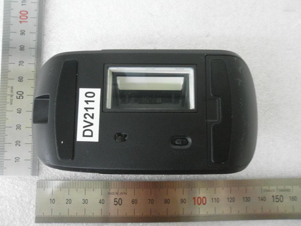
External Photos
FCCID: SSNCMR1400 Copyright Ⓒ 2013, DIGITAL EMC Co., Ltd. View 1 FCCID: SSNCMR1400 Copyright Ⓒ 2013, DIGITAL EMC Co., Ltd. View 2 FCCID: SSNCMR1400 Copyright Ⓒ 2013, DIGITAL EMC Co., Ltd. View 3
ID Label/Location Info
FCC ID: SSNCMR1400 Copyright Ⓒ 2013, Digital EMC Co., Ltd. FCC ID SAMPLE LABEL & LOCATION LABELLING REQUIREMENTS PER §2.925 The Label shown shall be permanently affixed at a conspicuous location on the device and be readily visible to the user at the time of purchase - The FCC label shown is representative of the label that will appear on the radio when in production. Other information may also be included on this label. - The device is so small that it is not practicable to place the statement specified under 15.19 statement request, the information required by this paragraph shall be placed in a prominent location in the user's manual.
Internal Photos
FCCID: SSNCM1400 Copyright Ⓒ 2013, DIGITAL EMC Co., Ltd. View 1 FCCID: SSNCM1400 Copyright Ⓒ 2013, DIGITAL EMC Co., Ltd. View 2 FCCID: SSNCM1400 Copyright Ⓒ 2013, DIGITAL EMC Co., Ltd. View 3
Test Report
TRF-EM-003(00)081218 Copyright ○ c 2013, DIGITAL EMC CO., LTD. Page 2 of 19 Report No.: DREFCC1304-0142 To t a l 1 9 pages CONTENTS 1. General Remarks ........................................................................................................................ 3 2. Test Laboratory ........................................................................................................................... 3 3. General Information of EUT ....................................................................................................... 4 4. Test Summary ............................................................................................................................. 5 4.1 Applied standards and test results ........................................................................................... 5 4.2 Test environment and conditions ............................................................................................. 5 4.3 Test result Summary ................................................................................................................ 5 5. Test Set-up and operation mode ............................................................................................... 6 5.1 Principle of Configuration Selection ......................................................................................... 6 5.2 Test Operation Mode ............................................................................................................... 6 5.3 Support Equipment Used ......................................................................................................... 6 6. Test Results : Emission .............................................................................................................. 7 6.1 Conducted Disturbance ........................................................................................................... 7 6.2 Radiated Disturbance ............................................................................................................ 10 Appendix 1 ..................................................................................................................................... 18 List of Test and Measurement Instruments ............................................................................. 18 TRF-EM-003(00)081218 Copyright ○ c 2013, DIGITAL EMC CO., LTD. Page 3 of 19 Report No.: DREFCC1304-0142 To t a l 1 9 pages 1. General Remarks This report contains the result of tests performed by: DIGITAL EMC CO., LTD. Address : 683-3, Yubang-Dong, Cheoin-Gu, Yongin-Si, Gyeonggi-Do, 449-080, Korea http://www.digitalemc.com Tel: +82-31-321-2664 Fax: +82-31-321-1664 2. Test Laboratory Digital EMC Co., Ltd. has been accredited / filed / authorized by the agencies listed in the following table; Certificate Nation Agency Code Mark Accreditation Korea KOLAS 393 ISO/IEC 17025 Site Filing USA FCC 101842 678747 Test Facility list & NSA Data Canada IC 5740A-1 5740A-2 Test Facility list & NSA Data Japan VCCI C-1427 R-1364, R-3385 T-1442, G-338 Test Facility list & NSA Data Certification Korea KC KR0034 Test Facility list & NSA Data Germany TUV ROK1221C ISO/IEC 17025 Quality control in the testing laboratory is implemented as per ISO/IEC 17025 which is the “General requirements for the competent of calibration and testing laboratory”. TRF-EM-003(00)081218 Copyright ○ c 2013, DIGITAL EMC CO., LTD. Page 4 of 19 Report No.: DREFCC1304-0142 To t a l 1 9 pages 3. General Information of EUT Model No. Mouse Dongle Add Model No. CMR-1400 Serial No NONE Supplied Power for Test AC 120 V, 60 Hz Rating Power Supply DC 5 V (USB Power by PC) Applicant LG Electronics lnc. 50 Hyangjeong-dong, Heungdeok-gu, Cheongjusi, Chungcheongbuk-do, 361-480, Korea Manufacturer Intech Electronics Corp. Guan-Lan,Shenzhen City,GuangDong, China. Factory Intech Electronics Corp. Guan-Lan,Shenzhen City,GuangDong, China. TRF-EM-003(00)081218 Copyright ○ c 2013, DIGITAL EMC CO., LTD. Page 5 of 19 Report No.: DREFCC1304-0142 To t a l 1 9 pages 4. Test Summary 4.1 Applied standards and test results Test Items Applied Standards Results Conducted Disturbance ANSI C63.4:2003 C Radiated Disturbance ANSI C63.4:2003 C C=Comply N/C=Not Comply N/T=Not Tested N/A=Not Applicable The data in this test report are traceable to the national or international standards. 4.2 Test environment and conditions Test Items Test date (MM-DD) Temp ()°C Humidity (% R.H.) Conducted Disturbance 04-01 22 26 Radiated Disturbance 04-02 04-02 20 22 31 33 4.3 Test result Summary (1) Conducted Emission Frequency [MHz] Phase Result [dBμV] Detector Limit [dBμV] Margin [dB] 0.20019 N 30.8 Average 53.6 22.8 (2) Radiated Emission Frequency [MHz] Pol. Result [dB(μV/m)] Detector Limit [dB(μV/m)] Margin [dB] 2658.807 H 46.3 Average 54.0 7.7 TRF-EM-003(00)081218 Copyright ○ c 2013, DIGITAL EMC CO., LTD. Page 6 of 19 Report No.: DREFCC1304-0142 To t a l 1 9 pages 5. Test Set-up and operation mode 5.1 Principle of Configuration Selection Emission : The equipment under test (EUT) was configured to measure its highest possible radiation level. The test modes were adapted accordingly in reference to the instructions for use. 5.2 Test Operation Mode - WIRELESS MOUSE RECEIVER MODE 5.3 Support Equipment Used Unit Model No. Serial No. Manufacturer CABLE BackshellFCC ID Connect type Length (m) shield NOTE-PC 4230S CNU20935R8 HP DC IN USB DSUB USB 1.2 - 1.2 1.6 Shield - Shield Shield Plastic DOC NOTE-PC TA Series PPP009L-E WBGST0A1R1T 2TC LITE-ON TECHNOLOGY DC IN POWER 1.2 1.6 Non-shield Non-shield Plastic DOC LCD MONITOR W2453VQV 104NDKDEJ101 LG Electronics Inc. POWER DSUB 1.6 1.2 Non-shield Shield Plastic DOC USB MOUSE 1484 352700021374 Microsoft Corporation USB 1.6 Shield Plastic DOC TRF-EM-003(00)081218 Copyright ○ c 2013, DIGITAL EMC CO., LTD. Page 7 of 19 Report No.: DREFCC1304-0142 To t a l 1 9 pages 6. Test Results : Emission 6.1 Conducted Disturbance 6.1.1 Measurement Procedure In the range of 0.15 MHz …
Text truncated - open the document above for the full version.
Test Setup Photos
Copyright © 2013, DIGITAL EMC Co., Ltd. CE TEST PICTURE Copyright © 2013, DIGITAL EMC Co., Ltd. RE TEST PICTURE < 30 MHz ~ 1 GHz > Copyright © 2013, DIGITAL EMC Co., Ltd. < (1 ~ 6) GHz >
Contact Information
Applicant
Hyun Su Park(Research Engineer)
Test Firm
Dt&C Co., Ltd.Lee Sang-Wook
Technical Specifications
| # | Rule Parts | Frequency Range | Power Output |
|---|---|---|---|
| 1 | 15B | - | - |
Other Applications from LG Electronics Inc.
SSNLSM3001306
Aug 11, 2013Wireless Scanner Mouse
Equipment Class
DXX - Part 15 Low Power Communication Device Transmitter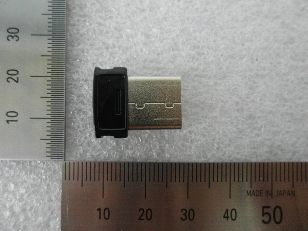
SSNLSM300R
Aug 11, 2013Wireless USB Receiver
Equipment Class
DXX - Part 15 Low Power Communication Device Transmitter
SSNBTS1
Jul 09, 2013Bluetooth Stereo Headset
Equipment Class
JBP - Part 15 Class B Computing Device PeripheralSSNCM1400
Apr 22, 2013Wireless MOUSE
Equipment Class
DSS - Part 15 Spread Spectrum Transmitter
SSNMNC4U1106
Jun 27, 2011Wireless Mouse
Equipment Class
DXX - Part 15 Low Power Communication Device Transmitter