STENRPCS10BNOTCHCELL Repeater
R-tron Inc.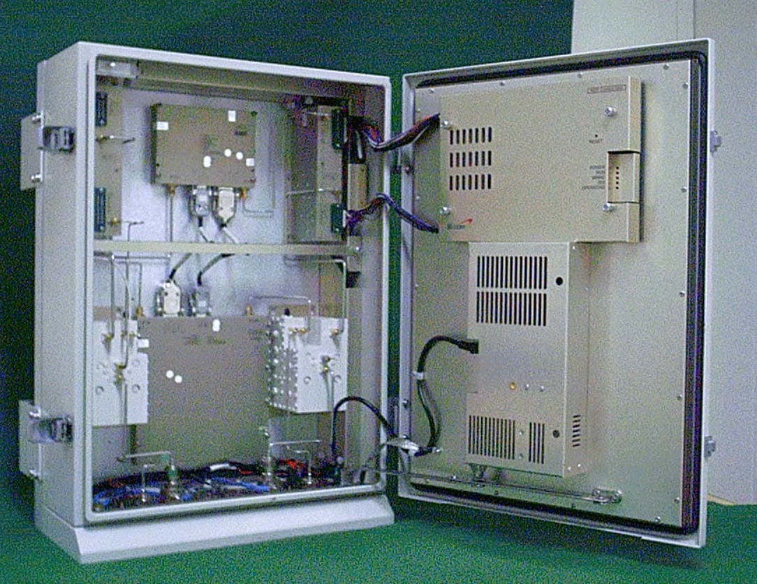
Click to zoom
Application Details
- Equipment Class
- PCB - PCS Licensed Transmitter
- Date of Grant
- Jan 10, 2005
- Application Purpose
- Original Equipment
- Date of Application
- Jan 10, 2005
- Equipment Note
- NOTCHCELL Repeater
- Frequency Range
- 1870.00000000 - 1885.00000000
- Company
- R-tron Inc.
- Country
- South Korea
Documents & Files
Document Text
Text extracted from the exhibit documents filed with the FCC. Open a document above to read the original.
Users Manual
R-TRON Proprietary & Confidential Page 1 1900D NOTCHCELL Repeater System Description SD-UPD10N-04A(V1.2) R-TRON Proprietary & Confidential Page 2 Copyright Copyright of this manual belongs to R-TRON, Inc. Reproduction, distribution or revision of part or all of contents in this manual in any form without written permission of R-TRON, Inc. is prohibited. Registered Trademark R-TRON are registered trademarks of R-TRON, lnc. Other products and company names mentioned herein this manual might be trade marks or trade names of their respective owners. RF Repeater Band Selective Type Sprint PCS English Copyright © 2004 R-TRON, Inc. All Rights Reserved The results of using the information not mentioned in this manual or the risk of misunderstanding this document remain with the user. The information in this manual is subject to change due to function enhancement, change of design, etc. If you want the modified manual or have any question on this manual, please contact us with information below: Address : Customer Support Center, Jisan IT Venture Bldg., 2/3F, 1004-9/10, Doksan- Dong, Gumcheon-Gu, Seoul 153-829 , South Korea Tel : +82-2-896-4101 R-TRON Proprietary & Confidential Page 3 Revision History Version Date of revision Reason for revision Revision Description V1.0 Dec.01.2004 First Edition V1.1 Dec.17.2004 Second Edition 2.1 System specification 5.12 Connection Ports V1.2 JAN.11.2005 Third Edition 2.1.2 System Features Caution fact addition R-TRON Proprietary & Confidential Page 4 CONTENTS 1. Overview ----------------------------------------------------------------------------------------------------- 5 2. Repeater Design -------------------------------------------------------------------------------------------- 7 2.1 System specification ----------------------------------------------------------------------------------- 7 2.1.1 Environmental conditions ---------------------------------------------------------------------- 7 2.1.2 System features ---------------------------------------------------------------------------------- 7 3. Repeater Configurations --------------------------------------------------------------------------------- 9 3.1 Main Box------------------------------------------------------------------------------------------------ 9 3.2 PSU Box ----------------------------------------------------------------------------------------------- 10 3.3 Sub Unit Overview ----------------------------------------------------------------------------------- 10 3.3.1 UDC(Up-Down Converter unit) with LNA -------------------------------------------------10 3.3.2 MCPA(Multi Carrier Power Amplifier unit) ----------------------------------------------- 11 3.3.3 ARCU(Advanced Repeater Control Unit board) ------------------------------------------ 12 3.3.4 DPX(Duplexer) --------------------------------------------------------------------------------- 12 3.3.5 PSU(Power Supply Unit) --------------------------------------------------------------------- 13 3.3.6 Heat Module ------------------------------------------------------------------------------------ 13 3.3.7 ARIU(Advanced Repeater Interface Unit board) ------------------------------------------ 14 3.3.8 Arrestor ------------------------------------------------------------------------------------------ 14 3.3.9 EMI/EMC Filter -------------------------------------------------------------------------------- 14 4. Block Diagram --------------------------------------------------------------------------------------------- 15 4.1 Downlink signal path -------------------------------------------------------------------------------- 15 4.2 Uplink signal path ------------------------------------------------------------------------------------ 15 4.3 Band Selective Repeater ---------------------------------------------------------------------------- 15 4.4 Repeater Setup ---------------------------------------------------------------------------------------- 16 5. Board and Unit Descriptions --------------------------------------------------------------------------- 16 5.1 MCPA for downlink --------------------------------------------------------------------------------- 16 5.2 PA for uplink ------------------------------------------------------------------------------------------ 17 5.3 UDC for downlink ----------------------------------------------------------------------------------- 18 5.4 UDC for uplink --------------------------------------------------------------------------------------- 20 5.5 ARCU -------------------------------------------------------------------------------------------------- 22 5.6 ARIU --------------------------------------------------------------------------------------------------- 23 5.7 DPX ----------------------------------------------------------------------------------------------------- 24 5.8 Arrester ------------------------------------------------------------------------------------------------- 26 5.9 PSU ----------------------------------------------------------------------------------------------------- 26 5.10 EMI/EMS Filter ------------------------------------------------------------------------------------- 27 5.11 Heater Module --------------------------------------------------------------------------------------- 28 5.12 Connector Ports -------------------------------------------------------------------------------------- 29 5.12.1 Local OMT port ; Main Box ---------------------------------------------------------------- 29 5.12.2 AC IN; Main Box ---------------------------------------------------------------------------- 29 5.12.3 AC IN; PSU Box ----------------------------------------------------------------------------- 30 5.12.4 DC IN 24V; PSU Box ------------------------------------------------------------------------ 30 R-TRON Proprietary & Confidential Page 5 System Description NOTCHCELL Repeater R-TRON Proprietary & Confidential Page 6 1 Overview R-TRON NOTCHCELL repeaters are used to fill out …
Text truncated - open the document above for the full version.
Cover Letter(s)
Jisan IT Venture Bldg., 2/3F, 1004-9/10, Doksan-Dong, Gumcheon-Gu, Seoul 153-829, Korea Tel: +82-2-896-4101 Fax: +82-2-896-4107 [email protected] December 16. 2004 Federal Communication Commission Equipment Authorization Branch 7435 Oakland Mills Road Columbia, MID 21046 In re : R-TRON, Inc. FCC ID: STENRPCS10D RF Repeater (PCS Block D) Part 24 Certification Request for Confidentiality Gentlemen: In accordance with 0.459 of CFR 47, R-TRON, Inc. hereby requests confidentiality of the Block Diagram, Circuit Diagrams, Repeater System Description, Technical Specification, Parts List, EUT Photographs and Tune-Up Procedure for the above-referenced certification application. These documents contain detailed system and equipment description and related information about the product which R-TRON, Inc. Considers to be proprietary, confidential, and a custom design and, otherwise, would not release to the general public. Since this design is a basis from which future technological products will evolve, R-TRON, Inc. considers this information to be of benefit to its competitors, such that the disclosure of the information in these documents would give competitors an unfair advantage in the market. Sincerely, ---------------------------------------------- G.H.Kim General Manager / R&D Center R-TRON, Inc.
Cover Letter(s)
Jisan IT Venture Bldg., 2/3F, 1004-9/10, Doksan-Dong, Gumcheon-Gu, Seoul 153-829, Korea Tel: +82-2-896-4101 Fax: +82-2-896-4107 [email protected] December 16. 2004 Federal Communication Commission Authorization and Evaluation Div. Equipment Authorization Branch 7435 Oakland Mills Road Columbia, MID 21046 In re : R-TRON, Inc. FCC ID: STENRPCS10D Request for Short-Term Confidentiality Dear Sirs, In accordance with 0.457 and 0.459 of CFR 47, R-TRON, Inc. requests short-term confidentiality for the test setup photos, external photos, internal photos, and user’s manual of the attached test report. These documents contain detailed system and equipment descriptions and related information about the product, which R-TRON, Inc. considers to be proprietary, confidential, and a custom design and otherwise, would not release to the general public. Since this design is a basis from which future technological products will evolve, R-tron feels that this information would be of benefit to its competitors, and that the disclosure of the information in these documents would give our competitors an unfair advantage in the market. Sincerely, ---------------------------------------------- G.H.Kim General Manager / R&D Center R-TRON, Inc.
Cover Letter(s)
American Telecommunications Certification Body Inc. 6731 Whittier Ave, McLean, VA 22101 December 19, 2004 RE: FCC ID: STENRPCS10D_ATCB002017 Attention: Jay Kim I have a few comments on this Application. Please note that further comments may arise in response to answers provided to the questions below. 1. As this device has two antenna inputs it is not an amplifier as defined by the FCC. AS this device appears to be more in line with what the FCC calls a booster or repeater operating in the PCS bands it would therefore be a PCB equipment code. Please correct your 731 form to be in line with the accepted FCC rules. 2. Please note that this is a licensed device not subject to part 15 except as a digital device. As such, please explain why the part 15 2-condition statement has been included in the label. 3. Please provide the manual for this device. 4. Please note that for booster and other subclasses of amplifiers it is important that the device reproduce the input faithfully. This means that in order to determine if this is properly being done, the input plots are also required. Please provide all input plots for all signals provided in the report. Please provide input and output for all modulation types used in the booster. 5. Please note that as this device is a subclass of amplifier that operates over a range of frequencies, intermodulation testing is also required. Please provide the necessary intermodulation test data in accordance with FCC rules. 6. Please note that the FCC ID needs to be on the outside of the device. Please provide a location drawing showing the label on the outside, or alternately, please provide evidence that the location of the label is acceptable. 7. Please provide the necessary rf exposure information for this device. Dennis Ward mailto:[email protected] The items indicated above must be submitted before processing can continue on the above referenced application. Failure to provide the requested information may result in application termination. Correspondence should be considered part of the permanent submission and may be viewed from the Internet after a Grant of Equipment Authorization is issued. Please do not respond to this correspondence using the email reply button. In order for your response to be processed expeditiously, you must submit your documents through the AmericanTCB.com website. Also, please note that partial responses increase processing time and should not be submitted. Any questions about the content of this correspondence should be directed to the sender.
External Photos
Main Box < Front View > < Rear View > < The Inside of the Repeater > PSU Box < Front View > < Rear View > < The Inside of PSU Box >
Test Report
Report Number: ESTR0412-005 Dates: December 14, 2004 Page 1 of 26 FCC ID: STENRPCS10D EUT Type: RF Repeater (CDMA) Test Report Report Number ESTR0412-005 Company Name R-TRON, Inc. Address Jisan IT Venture Bldg., 2/3F, 1004-9/10, Doksan-Dong, Gumcheon-Gu, Seoul, Korea Applicant Telephone 82-2-896-4101 Product Name RF Repeater(CDMA) Model No. LGNR 1900CD-10S Manufacturer R-TRON, Inc. Serial No. NONE Country of origin Korea Product Date of Receipt 2004-12-7 Date of Issue 2004-12-14 Testing Lab. ESTECH. Co., Ltd Standard FCC PART 24 , PART 2 Tested by S.R. Kim/ Engineer (Signature) Approved by Jay Kim/ Manager Engineer (Signature) * Note - This test report is not permitted to copy partly without our permission - This test result is dependent on only equipment to be used - This test result based on a single evaluation of one sample of the above mentioned Report Number: ESTR0412-005 Dates: December 14, 2004 Page 2 of 26 FCC ID: STENRPCS10D EUT Type: RF Repeater (CDMA) TABLE OF CONTENTS ATTACHMENT: TEST RESULT CERTIFICATION............................ 1 1. INTRODUCTION.....................................................................3 2. DESCRIPTION OF EUT............................................................. 4 3. DESCRIPTION OF TEST.......................................................... .. 5 4. TEST DATA 4.1 RF POWER OUTPUT........................................................7 4.2 OCCUPIED BANDWIDTH ................................................8 4.3 FIELD STRENGTH OF SPURIOUS RADIATION .....................9 4.4 SPURIOUS EMISSION AT ANTENNA TERMINAL................... 11 4.5 FREQUENCY STABILITY................................................... 13 5. TEST PLOTS 5.1 RF POWER OUTPUT...........................................................15 5.2 OCCUPIED BANDWIDTH .............................................................19 5.3 SPURIOUS EMISSION AT ANTENNA TERMINAL....................23 Report Number: ESTR0412-005 Dates: December 14, 2004 Page 3 of 26 FCC ID: STENRPCS10D EUT Type: RF Repeater (CDMA) 1. INSTROCTION 1.1 General This EUT (Equipment Under Test) has been shown to be capable of compliance with the applicable technical standards and tested in accordance with the measurement procedures as indicated in this report ESTECH Lab attests to accuracy of test data. All measurement reported herein were performed by ESTECH Co., Ltd. ESTECH Lab., assume full responsibility for the completeness of these measurements and vouch for the qualifications of all persons taking them. 1.2 Test Lab. Corporation Name: ESTECH Co. Ltd. Head Office: 3 rd Fl., Chungdam Bldg., 119-1, Chungdam-dong Kangnam-gu , Seoul, Korea (Safety & Telecom. Test Lab) EMC Test Lab.: 58-1, Osan-Ri, GaNam-Myon, YeoJoo-Gun, KyungKi-Do, Korea 97-1, Hoiuk-Ri Majang-Myon, Icheon-city, KyungKi-Do, Korea Report Number: ESTR0412-005 Dates: December 14, 2004 Page 4 of 26 FCC ID: STENRPCS10D EUT Type: RF Repeater (CDMA) 2. Description of EUT 2.1 Summary of Equipment Under Test ♦ FCC ID : STENRPCS10D ♦ Date of Test : 2004.12.07 – 2004.12.14 ♦ Model No. : LGNR 1900CD-10S ♦Freq. Range : - Downlink: 1945 ~ 1950MHz - Uplink: 1865 ~ 1870MHz ♦ Power Rating : AC110V, 50/60Hz ♦ EUT Type : RF Repeater(CDMA), 1900MHz PCS Block D . Report Number: ESTR0412-005 Dates: December 14, 2004 Page 5 of 26 FCC ID: STENRPCS10D EUT Type: RF Repeater (CDMA) 3. DESCRIPTION OF TEST 3.1 RF Power Output - The EUT is a bi-directional amplifier repeater on A-band frequency for broadband PCS. Downlink input (from Base station direction) is connected to a signal generator. Downlink output is connected spectrum analyzer through proper attenuator. The input to the amplifier is set such that the maximum power output is achieved at customer supplied antenna connector. The power measurement method of Uplink is also same way. 3.5 Occupied Bandwidth The signal (Down/Up) input is connected to the signal generator. The input to the amplifier is set such that the maximum power output is achieved at the customer supplied antenna connector (at the antenna connector of base station). Maximum Allowable Downlink Power Output is 40dBm and Maximum Allowable Uplink Power Output is 25dBm. The signal output is connected to the spectrum analyzer. The VBW is set to 3 times the RBW. The sweep time is coupled. 3.6 Spurious and Harmonic Emission at Antenna Terminal The various conducted spurious and harmonic frequencies is measured by means of a calibrated spectrum analyzer. The spectrum is scanned from the lowest frequency generated in the equipment up to 20GHz. Set the RES BW to 1% of the emission bandwidth to show compliance with the -13dBm, limit, in the 1MHz bands immediately outside and adjacent to the top and bottom edges of the frequency block. For the Out-of-Band measurements a 1MHz RBW was used to scan from 30MHz to 10xfo of the fundamental carrier for all frequency block. A display line was placed at -13dBm to show compliance for spurious, and harmonics. Inter-modulation Attenuation Test (3 Signal Method) Blocks Tested: A-F Downlink/Uplink Modulation Tested: Three input signals are chosen such that in the 15MHz channel blocks the lowest and highest channels are selected in addition to the second lowest channel. In the 5MHz channel blocks the lowest and highest channels are selected in addition to the second lowest channel. 3.7 Radiation Spurious and Harmonic Emissions Radiation and harmonic emission are measured outdoors at our 3 meters test range. The equipment under test is placed on a wooden turntable 3 meters from the receive antenna. The receive antenna height and turntable rotations were adjusted for the highest reading on the receive spectrum analyzer. A half wave dipole was substituted in place of the EUT. This dipole antenna was driven by a signal generator with the level of the signal generator being adjusted to obtain the same receive spectrum analyzer reading. This level is recorded. For readings above 1GHz, the above procedure is repeated using horn an…
Text truncated - open the document above for the full version.
Test Report
5. TEST PLOTS - Inter-modulation Signal Plot A band-Downlink/Uplink(Lowest & Highest Channel) Downlink- CH 25 & 50 Downlink- CH 250 & 275 EUT Type: RF Repeater (CDMA) Dates: December 14, 2004 Page 1 of 6 5. TEST PLOTS (CONTINUED) Uplink- CH 25 & 50 Uplink- CH 250 & 275 EUT Type: RF Repeater (CDMA) Dates: December 14, 2004 Page 2 of 6 5. TEST PLOTS (CONTINUED) B band-Downlink/Uplink(Lowest & Highest Channel) Downlink- CH 425 & 450 Downlink- CH 650 & 675 EUT Type: RF Repeater (CDMA) Dates: December 14, 2004 Page 3 of 6 5. TEST PLOTS (CONTINUED) Uplink- CH 425 & 450 Uplink- CH 650 & 675 EUT Type: RF Repeater (CDMA) Dates: December 14, 2004 Page 4 of 6 5. TEST PLOTS (CONTINUED) D band-Downlink/Uplink(Lowest & Highest Channel) Downlink- CH 325 & 350 Downlink- CH 350 & 375 EUT Type: RF Repeater (CDMA) Dates: December 14, 2004 Page 5 of 6 5. TEST PLOTS (CONTINUED) Uplink- CH 325 & 350 Uplink- CH 350 & 375 EUT Type: RF Repeater (CDMA) Dates: December 14, 2004 Page 6 of 6
Test Report
5. TEST PLOTS - Input Signal Plot A band-Downlink/Uplink(Middle Channel) CH 150 EUT Type: RF Repeater (CDMA) Dates: December 14, 2004 Page 1 of 3 5. TEST PLOTS (CONTINUED) B band-Downlink/Uplink(Middle Channel) CH 550 EUT Type: RF Repeater (CDMA) Dates: December 14, 2004 Page 2 of 3 5. TEST PLOTS (CONTINUED) D band-Downlink/Uplink(Middle Channel) CH 350 EUT Type: RF Repeater (CDMA) Dates: December 14, 2004 Page 3 of 3
Contact Information
Applicant
Yong Hoon Kang
Technical Contact
Technical Specifications
| # | Rule Parts | Frequency Range | Power Output | Emission | Tolerance |
|---|---|---|---|---|---|
| 2 | 24E | 1.87 GHz - 1.89 GHz | 313.00 mW | F9W | Amp |
Other Applications from R-tron Inc.

STE-APEX8930
Dec 05, 2011RF Repeater
Equipment Class
TNB - Licensed Non-Broadcast Station Transmitter
STE-QUADCOMM-700N
Oct 19, 2011LTE Repeater
Equipment Class
TNB - Licensed Non-Broadcast Station Transmitter
STE-APEX730
Oct 14, 2011LTE Band Repeater
Equipment Class
TNB - Licensed Non-Broadcast Station Transmitter
STE-APEX1924
Apr 27, 2011Repeater
Equipment Class
PCB - PCS Licensed Transmitter
STE-APEX1930
Apr 25, 2011Repeater
Equipment Class
PCB - PCS Licensed Transmitter